
Flare System Considering Combustion, CFD Simulation, ANSYS Fluent Training
$140.00 Internship
- The problem numerically simulates the Combustion in a Gas Flare system using ANSYS Fluent software.
- We design the 3-D model by the Design Modeler software.
- We Mesh the model by ANSYS Meshing software, and the element number equals 1043138.
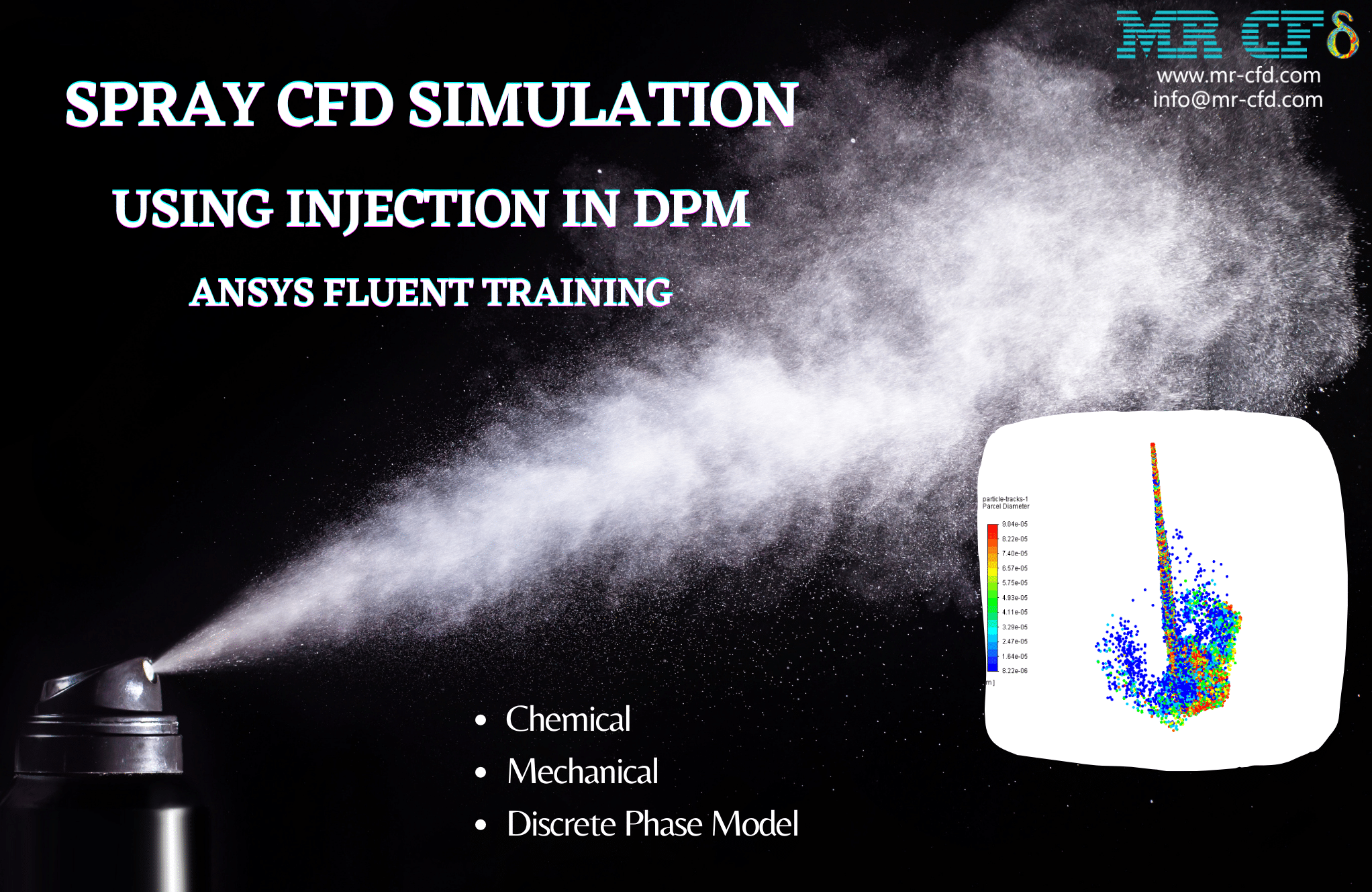
- We use the Species Transport model to define the chemical reaction.
To Order Your Project or benefit from a CFD consultation, contact our experts via email (info@mr-cfd.com), online support tab, or WhatsApp at +44 7443 197273.
There are some Free Products to check our service quality.
If you want the training video in another language instead of English, ask it via info@mr-cfd.com after you buy the product.
Description
Description
The current project simulates combustion in a gas flare system using ANSYS Fluent software. We perform this CFD project and investigate it by CFD analysis.
The present model is designed in three dimensions using Design Modeler software. Due to the model’s symmetrical structure and to reduce the computational cost, only a 120-degree segment of the geometry is modeled.
The flare model has a cylindrical structure located inside a cylindrical computing space. Different sections, such as steam, gas flow, and pilot, are defined at the tip of the flare.
The meshing of the model has been done using ANSYS Meshing software. The element number is 1043138.
Flare Methodology
The flare system, also known as a gas flare, is a combustion device used in industrial units such as oil and gas refineries and the production of oil and gas wells, especially on offshore platforms. The Species Transport model has been used to carry out this project.
The transition species’ defined material is an n-butane-air mixture consisting of 9 gaseous species, including C4H10, O2, CO2, H2O, H2, CH4, C2H6, C3H8, and N2.
The volumetric model is also activated to activate chemical reactions and, consequently, the combustion process. This burning process consists of five different chemical reactions in the following form.

At the tip of the flare, a gas flow with a flow rate of 0.09259 kg/s enters the environment in the form of a combination of hydrocarbons. At the same time, a methane flow from the pilot flame and a steam flow from the steam inlet boundary, both at velocities of 2.479 m/s, enter the domain to ignite the mixture.
Also, the standard k-epsilon model can solve the turbulent fluid equations and the energy equation, which is used to calculate the temperature change within the combustion chamber.
Flare Conclusion
At the end of the solution process, three-dimensional contours related to the velocity and mass fraction of each gas species modeled in this simulation are obtained.
For example, by examining the three-dimensional contour of carbon dioxide gas, it can be well understood that the chemical reaction of combustion and carbon dioxide gas production is performed.
Also, as can be seen, the mass fraction of species considered in the fuel mixture decreases as we get away from the fuel inlet boundary. In contrast, the mass fractions of chemical species of reaction products increase along this way.
Reviews
You must be logged in to post a review.
Milton Parisian –
What are the potential applications of this simulation?
MR CFD Support –
This simulation can be used in a variety of industrial applications where flare systems are used, such as oil and gas production, chemical manufacturing, and waste treatment facilities.
Bailey White –
This project surely enhanced my CFD skills, particularly in modelling combustion processes. The detailed explanation of chemical reactions was very helpful. Is there any section within the training that glosses over possible optimization of the flare system to reduce pollutant outputs?
MR CFD Support –
Thank you for your positive feedback! Yes, within the training material, there is a section dedicated to discussing optimization techniques for flare systems that aim to enhance the efficiency of combustion, thereby reducing the emission of pollutants. This includes adjustments to the combustion process and design modifications to promote complete combustion and minimize the release of harmful gases.
Krista Christiansen –
How does the flare system work in this CFD simulation?
MR CFD Support –
The flare system in this CFD simulation works by burning off the unwanted gases during industrial processes. It ensures that these gases are safely disposed of, reducing the risk of explosion and minimizing the environmental impact.
Priscilla Vandervort –
How can I customize the simulation for my specific needs?
MR CFD Support –
The simulation can be customized by changing the properties of the gas and the flare system according to your needs. You can also modify the boundary conditions to match your specific situation.
Petra Schaden –
I found the integration of combustion chemistry impressive in this flare system simulation. The accurate replication of various chemical species and their mass fractions is crucial,
MR CFD Support –
Thank you for the positive feedback on our combustion simulation approach. We take great care in accurately modeling the chemical processes to provide realistic results, and we’re glad that you appreciate the complexities and details of our CFD projects.
Mr. Timmothy Crooks III –
I’m very impressed with the comprehensive level of detail in the flare system simulation! The combustion process seems to be modeled with thorough understanding and expertise.
MR CFD Support –
Thank you for your kind words! We’re delighted to hear that you are satisfied with the detail and accuracy of our flare system simulation. Our team strives to ensure a comprehensive understanding and precise modeling for authentic CFD analysis results.
Estefania Reynolds –
I’m highly impressed by the detailed modeling of the gas flare system. The use of different chemical species for the combustion simulation seems thorough. Great job incorporating complex reactions and achieving identifiable results.
MR CFD Support –
Thank you for your kind words and appreciation of our gas flare system simulation training product. We strive to provide a comprehensive learning experience, and we’re glad you recognized the effort put into our detailed modeling and combustion analysis. We look forward to providing more quality simulations for your educational needs!
Mireya Jast –
The simulation of the combustion process in a gas flare system seems very comprehensive. What is the model’s behavior at different operational scenarios, like variable fuel compositions or flow rates? Are there specific case studies included that explor how the system would respond to those changes?
MR CFD Support –
The training includes review and analysis of the combustion process under the current operating conditions provided in the project description. Additional scenarios with variable fuel compositions or flow rates are typically explored in more advanced or separate case studies. Users interested in such analyses can perform their custom simulations varying the parameters within ANSYS Fluent using the provided model as a basis.
Prof. Lonny Nolan MD –
The training details are very thorough, but I was wondering if the simulation also accounts for environmental factors like wind, which might affect the flare’s behavior?
MR CFD Support –
In this particular simulation, environmental factors such as wind may not be explicitly modeled. However, it is possible to include wind and other environmental effects in flare simulations by defining additional boundary conditions and carrying out a more comprehensive analysis. For specific design needs, incorporating these extra variables could provide more realistic results concerning the flare’s performance under varying environmental conditions.