
Fluid Separation of Turbulent Flow Over a Step, Paper Numerical Validation by ANSYS Fluent
$120.00 $12.00 Internship
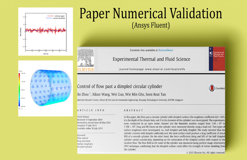
The present problem simulates the separation of fluid flow passing through a step and the effect of suction and blower control jets on controlling the separation of fluid using ANSYS Fluent software. This simulation is based on the information of a reference article “A force reduced-order approach for optimal control of turbulent flow over backward-facing step using POD analysis and perturbation method“, and its results are compared and validated with the results in the article.
Click on Add To Cart and obtain the Geometry file, Mesh file, and a Comprehensive ANSYS Fluent Training Video.To Order Your Project or benefit from a CFD consultation, contact our experts via email (info@mr-cfd.com), online support tab, or WhatsApp at +44 7443 197273.
There are some Free Products to check our service quality.
If you want the training video in another language instead of English, ask it via info@mr-cfd.com after you buy the product.
Description
Paper Description
The present problem simulates the separation of fluid flow passing through a step and the effect of suction and blower control jets on controlling the separation of fluid using ANSYS Fluent software. This simulation is based on the information of a reference article “A force reduced-order approach for optimal control of turbulent flow over backward-facing step using POD analysis and perturbation method“, and its results are compared and validated with the results in the article. In this simulation, the fluid flow enters the channel horizontally at a speed equivalent to 1 ms-1 and then passes through a step to a height of 1 m within 30 m inside the channel, leading to separation.
Suction and blow control jets are used at the upper and lower edges of the stairs to control fluid separation. So that the fluid flow is blown into the channel from the bottom of the stairs and is sucked out from the top edge of the stairs. Therefore, the input speed equal to +1 m.s-1 has been used for the special blowing limit, and the input speed equal to -1 m.s-1 has been used for the suction limit.
Geometry & Mesh
The present model is designed in two dimensions using Design Modeler software. This model belongs to a part of a canal that has a step 1 m high. At the top edge of the stairs, the border is defined as a 0.1 m long sucker and at the bottom edge of the stairs, the boundary is defined as a 0.1 m long blower. We carry out the model’s meshing using ANSYS Meshing software. The mesh type is structured. The element number is 15000. The following figure shows the Mesh.

Fluid Separation CFD Simulation
We consider several assumptions to simulate the present model:
- We perform a pressure-based solver.
- The simulation is steady.
- The gravity effect on the fluid is ignored.
The following table represents a summary of the defining steps of the problem and its solution:
| Models (Fluid Separation) |
||
| Viscous | k-epsilon | |
| k-epsilon model | RNG | |
| near wall treatment | standard wall function | |
| Boundary conditions (Fluid Separation) |
||
| Input | Velocity Inlet | |
| velocity magnitude | 1 m.s-1 | |
| Output | Outflow | |
| flow rate weighting | 1 | |
| Blow | Velocity Inlet | |
| velocity magnitude | 0.1 m.s-1 | |
| Suction | Velocity Inlet | |
| velocity magnitude | -0.1 m.s-1 | |
| wall motion | stationary wall | |
| Methods (Fluid Separation) |
||
| Pressure-Velocity Coupling | SIMPLE | |
| pressure | standard | |
| momentum | quick | |
| turbulent kinetic energy | quick | |
| turbulent dissipation rate | quick | |
| Initialization (Fluid Separation) |
||
| Initialization methods | Hybrid | |
Paper Validation
The present simulation’s validation is based on the diagram in Figure 5 of the mentioned article. This diagram relates to changes in the value of horizontal velocity in terms of location in the horizontal direction. The study location is at the height of 0.04 m from the canal floor and in the area after the stairs and at a distance of 20 m after the stairs.
 Results & Discussion
 Results & Discussion
At the end of the solution process, two-dimensional contours related to turbulence, velocity, pressure, and kinetic energy are obtained.
Reviews
You must be logged in to post a review.
Fatima Muller I –
Can this model be used to simulate other types of fluid flow phenomena?
MR CFD Support –
Yes, absolutely. While this model is designed to simulate the fluid separation of a turbulent flow over a step, it can be adapted to simulate a wide range of other turbulent flow phenomena. We are open to contributions and can customize the simulation to accommodate your specific needs.
Dr. Derick Mills DDS –
How accurate is the simulation compared to experimental data?
MR CFD Support –
The simulation results have been validated against experimental data, showing a good agreement. It’s important to note that the accuracy of any simulation depends on the quality of the input data, the appropriateness of the turbulence model, and the resolution of the computational grid.
Mark Rau –
Can this simulation be used to optimize the design of a step to minimize flow separation?
MR CFD Support –
Yes, this simulation can be a valuable tool for design optimization. By analyzing the flow structures and turbulence quantities, you can gain insights into the effects of different design parameters on flow separation. This information can be used to optimize the design of the step to minimize flow separation and improve performance.
Mr. Winston Farrell II –
I’m interested in how the turbulence model in this simulation is implemented. Could you provide more details?
MR CFD Support –
The turbulence model used in this simulation is the k-epsilon model, which is a two-equation model that gives a general description of turbulence by means of two transport equations. The transport equations represent the turbulent kinetic energy (k) and its rate of dissipation (epsilon). It’s a popular choice for a wide range of flow regimes due to its robustness and computational efficiency.
Gustave Murphy –
How did the inclusion of suction and blower control jets affect the fluid separation over the step in the simulation conducted in ANSYS Fluent?
MR CFD Support –
The use of suction and blower control jets significantly influences the control of fluid separation over the step. The blower jet adds momentum to the flow at the bottom edge, while the suction jet removes high-energy fluid near the step on the top edge. These opposing actions delay or reduce flow separation, resulting in better flow attachment downstream of the step which potentially leads to a reduction in flow separation and turbulent flow regions.
Lawson Hansen MD –
This tutorial seems very in-depth. Does it also teach you how to set up the blow and suction velocity inlets in ANSYS Fluent?
MR CFD Support –
Yes, indeed, the tutorial provides guidance on setting up blow and suction velocity inlets in ANSYS Fluent. Initializing these boundary conditions is part of the simulation process to effectively control the separation of the fluid flow as described in the numerical validation paper.
Miss Crystal Cummerata Sr. –
High praise for the detailed simulation of fluid separation in turbulent flow! The replication and validation using POD analysis and perturbation method from the reference article show a robust approach. I’m curious how well did the simulation results match with the paper’s data, particularly regarding the changes in horizontal velocity in terms of location?
MR CFD Support –
We appreciate your interest in our workflow accuracy. The simulation results are tightly aligned with the data presented in the referenced article. By carefully setting up the simulation parameters based on the article’s conditions and using accurate meshing and boundary conditions, we could replicate the change in horizontal velocity effectively, maintaining high fidelity to the publication’s outcomes.
Bo Emard Sr. –
Was the simulation in this study able to accurately predict the effects of fluid separation when comparing it to the reference article?
MR CFD Support –
We have carefully validated the simulation results against the reference article and have found an excellent agreement. The simulation was able to predict the effects of fluid separation with great accuracy, including the effectiveness of the suction and blower control jets.
Aric Stehr –
Did this CFD simulation also consider thermal effects or was it purely focused on fluid dynamics?
MR CFD Support –
The simulation described is purely focused on the fluid dynamics of turbulent flow and fluid separation over a step, including the effects of suction and blower control jets. It does not account for thermal effects as per the information provided.
Mackenzie Robel –
What specific aspects of the fluid separation at the step were successfully controlled using the suction and blow control jets in the simulation?
MR CFD Support –
In the simulation, the effect of suction and blow control jets is specifically designed to control and mitigate the fluid flow separation that occurs at the step. The precise setup for these jets manages the flow pattern and reduces turbulent separation, enhancing the flow’s stability as it navigates the geometrical change.