FSI Analysis for a Ball in Water Flow, ANSYS Fluent CFD Simulation Training
$210.00 Student Discount
- The problem numerically simulates the FSI Analysis for a Ball in Water Flow using ANSYS Fluent software.
- We design the 3-D model with the Design Modeler software.
- We mesh the model with ANSYS Meshing software, and the element number equals 20192.
- We perform this simulation as unsteady (Transient).
- We use Dynamic Mesh to define the mesh deformation.
- We perform Fluid-Structure Interaction (FSI) to define system coupling between Fluent and Transient Structural.
Click on Add To Cart and obtain the Geometry file, Mesh file, and a Comprehensive ANSYS Fluent Training Video.
To Order Your Project or benefit from a CFD consultation, contact our experts via email ([email protected]), online support tab, or WhatsApp at +44 7443 197273.
There are some Free Products to check our service quality.
If you want the training video in another language instead of English, ask it via [email protected] after you buy the product.
Description
Description
The present problem simulates a spherical ball in water flow using ANSYS Fluent software using the FSI method.
The present model is designed in three dimensions using Design Modeler software. The model consists of a horizontal tube with a length of 0.02 m and a diameter of 0.001 m in which a spherical solid or ball with a diameter of 0.00009 m is placed.
We carry out the model’s meshing using ANSYS Meshing software. The element number is 20192.
Also, due to the nature of the present problem, the transient solver has been enabled.
Ball Methodology
We perform this simulation using FSI (fluid-solid interaction) method. In this simulation, a computational area is designed in the form of a horizontal tube filled with water flow; So that a solid or spherical object in the shape of a ball is immersed in it.
In such models, there is a need for instantaneous and time-dependent change in modeling the model based on the type of displacement at the adjacent mesh boundaries. In determining dynamic mesh methods, smoothing and remeshing methods have been used.
According to the smoothing method, the number of nodes does not change and only adjusts the mesh of an area by moving or deforming the boundaries. However, the remeshing method is used when the displacement of the borders is large compared to the size of the local cells to regenerate the destructive cells of the critical size limit.
To define areas with dynamic mesh, the pipe area is defined as stationary, and the wall around the ball is determined by system coupling with transient structural software. This means that the water flow location inside the pipe is constant relative to the ball, and the ball has no movement or rotation within the water flow.
The flow of water enters the tube at a speed equal to 0.001 m.s-1 and exits it at a pressure equal to atmospheric pressure. In the settings section of structural analysis software, the spherical body wall boundary is defined as fluid and solid interaction (fluid-solid interaction), i.e., this solid boundary can be affected by water flow behavior.
Then, it describes the type of data transfer between fluid and structural software in the system coupling section settings.
The definition of data transfer is defined from one boundary as a source in Fluent software to the same boundary as a target in Transient Structural software or vice versa in the form of a variable. For this simulation, two data transmissions are defined.
Thus, force is transferred from the fluid part to the structural part, and displacement is transferred from the structural part to the fluid region.
This means that the flow of water hits the spherical body with its movement, and the spherical body can also move inside the pipe. Moreover, the standard k-epsilon model is used to solve turbulent fluid equations.
Ball Conclusion
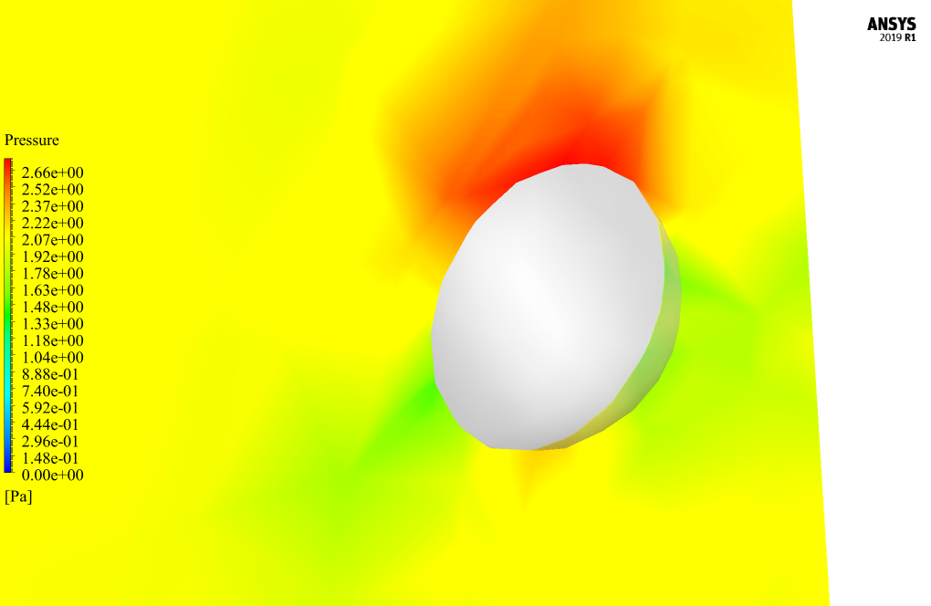
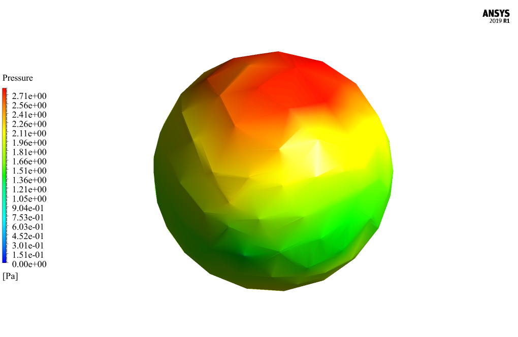
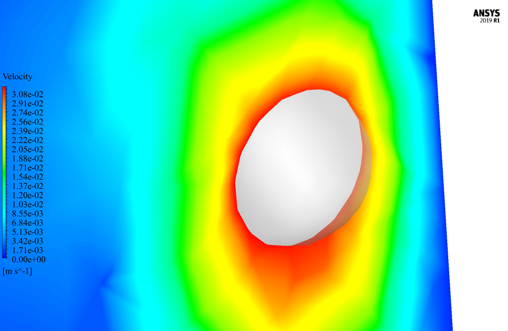
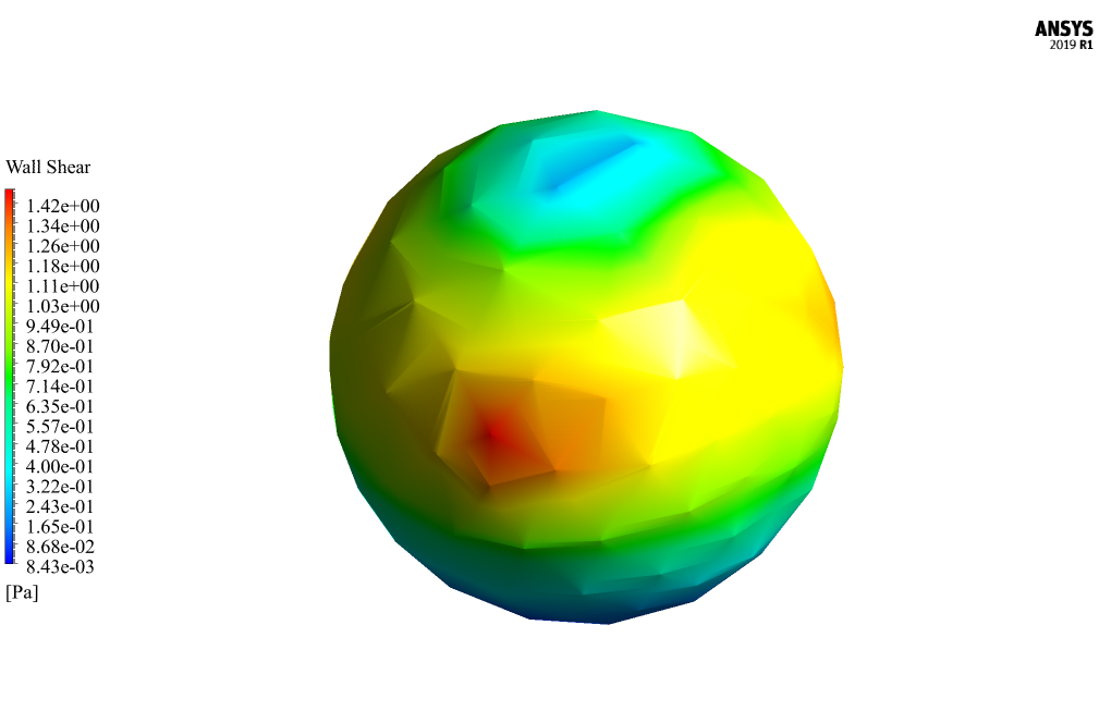
After the solution process, two-dimensional contours related to the pressure and shear stress on the surface of the body of the spherical body and two-dimensional contours related to the speed and pressure around the spherical body in the middle plate of the tube are obtained.
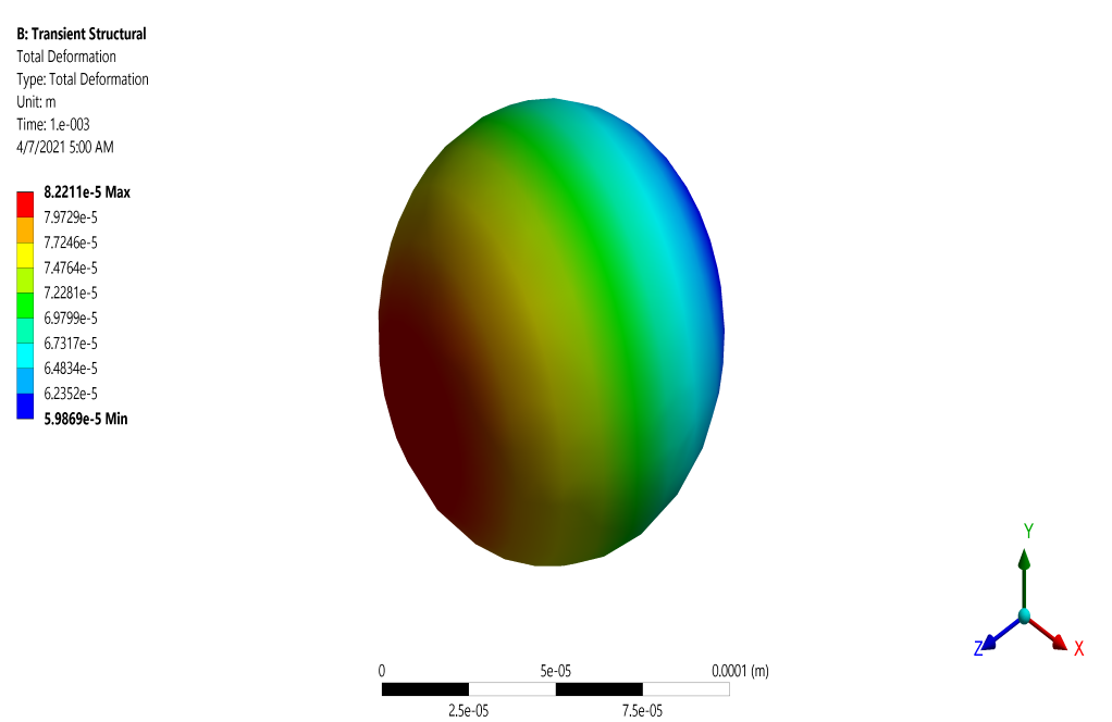
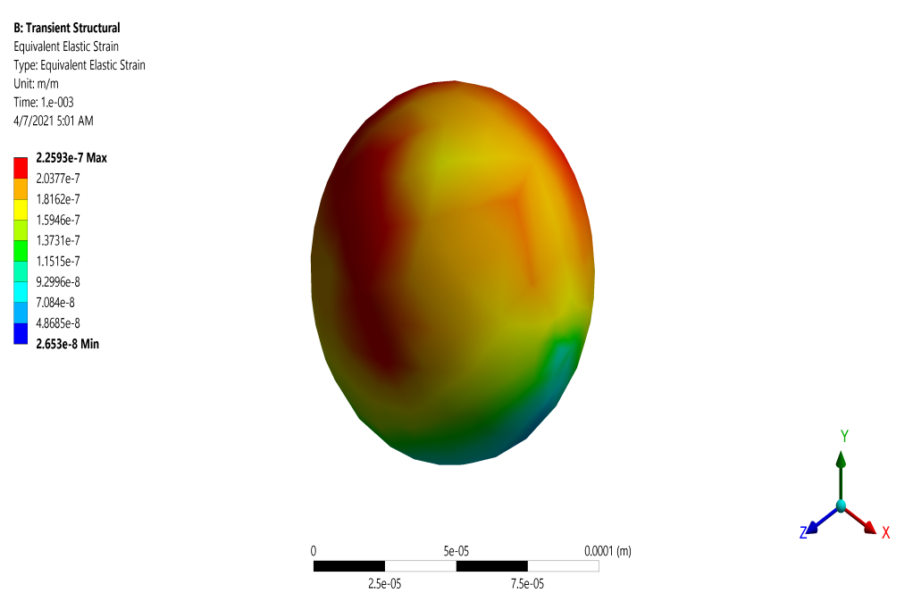
These contours correspond to the last second of the simulation process. Contours related to deformation and elastic strain are also obtained in the structural analysis section.
David Dicki I –
How did you ensure that the data transfer was accurately set up between the fluid part and the structural part in this simulation?
MR CFD Support –
In the mentioned FSI simulation, data transfer between the fluid and structural parts is managed through the ANSYS system coupling interface. The force resulting from the water flow upon the spherical body is defined as a source in Fluent and transferred as a target to the structural part in Transient Structural software, whereas the ball’s displacement from the structural analysis is sent back to Fluent to adjust the fluid mesh accordingly. Appropriate convergence criteria and time step setups ensure accurate data transfer.
Mabel Flatley –
I’m thrilled with how the FSI analysis of the spherical ball in water flow turned out. It was incredible to see how the ball interacts with the water flow and how the mesh adjusted to the dynamic movements. The visuals of the stress and deformation contours were very insightful for understanding the interactions at play.
MR CFD Support –
Thank you for your positive feedback! We’re delighted that you found the FSI analysis of the spherical ball in water flow thorough and the results clear and insightful. It’s great to hear that the visuals provided a deep understanding of the intricate interactions. We take pride in providing detailed simulations that help visualize complex dynamics, and we’re glad it served your learning needs!
Prof. Jamie Friesen –
The simulation results are excellent! It clearly demonstrates the dynamic interaction between the ball and the fluid flow. Great job on the visualization of the pressure and shear stress contours around the sphere.
MR CFD Support –
We’re thrilled to hear that you are satisfied with the simulation results and find the visualization of the pressure and shear stress contours useful. Thank you for taking the time to share your positive feedback!
Dr. Wilber Mayer –
This training sounds quite comprehensive. Thanks for showing how to couple Fluent and Transient Structural software for FSI simulations on a clear example. It’s great to see the detailed explanation of the dynamic mesh setup and data transfer methods. I learned a lot about simulation of spherical bodies in water flow using ANSYS Fluent.
MR CFD Support –
Thank you for your positive feedback! We are thrilled to hear that you found our training on FSI simulations with ANSYS Fluent insightful and beneficial for understanding the dynamics of spherical bodies in fluid flows. Your appreciation motivates us to continue creating detailed and comprehensive learning products. If you have any further questions or need assistance with other simulations, please feel free to reach out.
Clarissa Jenkins –
Does the simulation account for the possibility of the ball moving or rotating due to the water flow, and how does it track such movements?
MR CFD Support –
Yes, the simulation accounts for the ball’s movement and rotation due to the water flow through the FSI method. The dynamic meshing techniques of smoothing and remeshing are used to ensure the mesh adapts to the ball’s movement in time. Additionally, the system coupling allows for the transfer of data such as forces and displacement between the fluid and the structural components, enabling the tracking of the ball’s movements within the tube.
Cleveland Connelly –
I was really impressed by how detailed the FSI analysis for a ball in water flow simulation is. The containment of the physics in the system pair is great for future research and development in the engineering field.
MR CFD Support –
Thank you for your positive feedback. We are glad that you appreciate the detail and complexity involved in performing the FSI analysis for a ball in water flow simulation. It’s our goal to provide comprehensive and accurate simulations that can be a valuable resource for engineering research and development. If you have any more questions or need further information, please don’t hesitate to reach out.