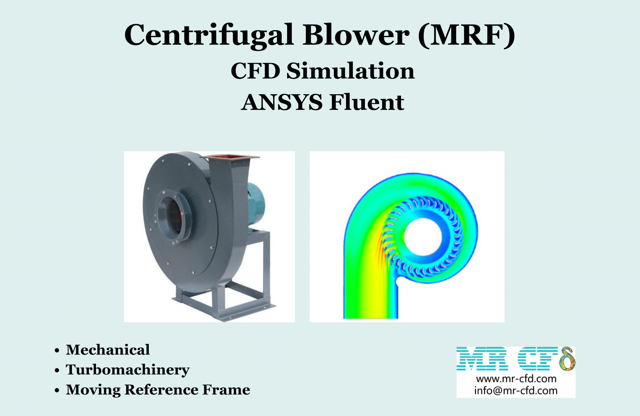
Centrifugal Blower (MRF) CFD Simulation, ANSYS Fluent
$80.00 Student Discount
- The problem numerically simulates Centrifugal Blower using ANSYS Fluent software.
- We design the 3-D model by the Design Modeler software.
- We Mesh the model by ANSYS Meshing software, and the element number equals 172824.
- We use the Frame Motion method to define rotational motion in cell zone conditions.
To Order Your Project or benefit from a CFD consultation, contact our experts via email ([email protected]), online support tab, or WhatsApp at +44 7443 197273.
There are some Free Products to check our service quality.
If you want the training video in another language instead of English, ask it via [email protected] after you buy the product.
Description
Description
This simulation is about a Centrifugal Blower via ANSYS Fluent software. We perform this CFD project and investigate it by CFD analysis.
The blower is a device for blowing high-pressure air, which generally has applications such as dust cleaning. For example, a blower is used to clean computer parts and equipment.
With its rotational motion, the central motor of this device creates high pressure in the air and directs this high-pressure air out of the device’s outlet. The blower designed in this modeling is centrifugal.
The centrifugal blower can absorb air from its central part, and then this airflow enters the central impellers in the form of a fin disc. The rotational motion of the blades at high speed causes the airflow to rotate.
The centrifugal force increases the air pressure and, consequently, the airflow’s velocity. Finally, this high-pressure air is directed to the outside environment through a duct installed on the blower’s outer body.
The present model is designed in two dimensions using Design Modeler software. The model is a two-dimensional centrifugal blower designed to reduce computational costs. Since the blower is centrifugal, the current input is from the model’s center, and its output is located in the model perimeter.
The model is then meshed by ANSYS Meshing software. The model mesh is unstructured, and 172824 cells have been created.
Centrifugal Blower Method
In this simulation, a zone around the blades is distinguished from the entire computational domain to define the rotational flow of air. The Frame Motion has been used for this zone in cell zone conditions.
Doing so assumes that instead of defining rotational motion for the blades at a given speed, rotational flow is defined for the air around the blades at the same speed. This rotational motion has a rotational speed of 260 rad/s.
Also, since the model’s prominent nature is related to pressure changes, the pressure boundary condition is used at the input (central part of the model) and the output (outer part of the model).
Centrifugal Blower Conclusion
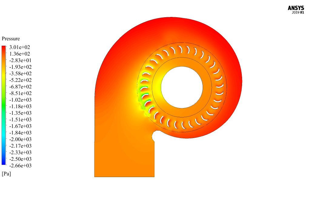
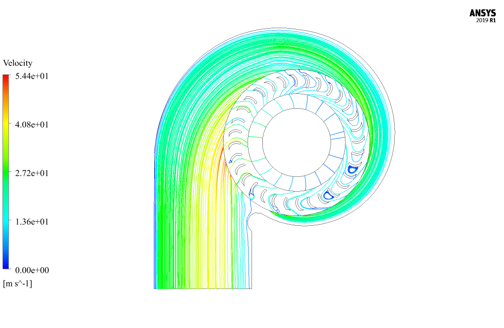
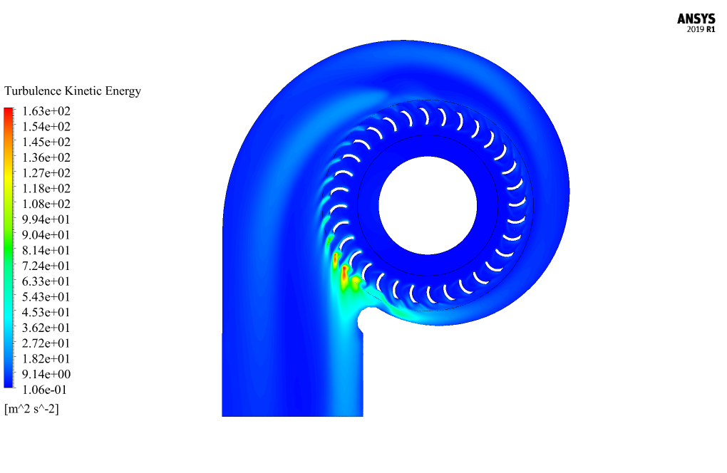
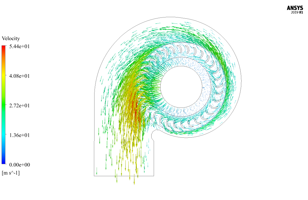
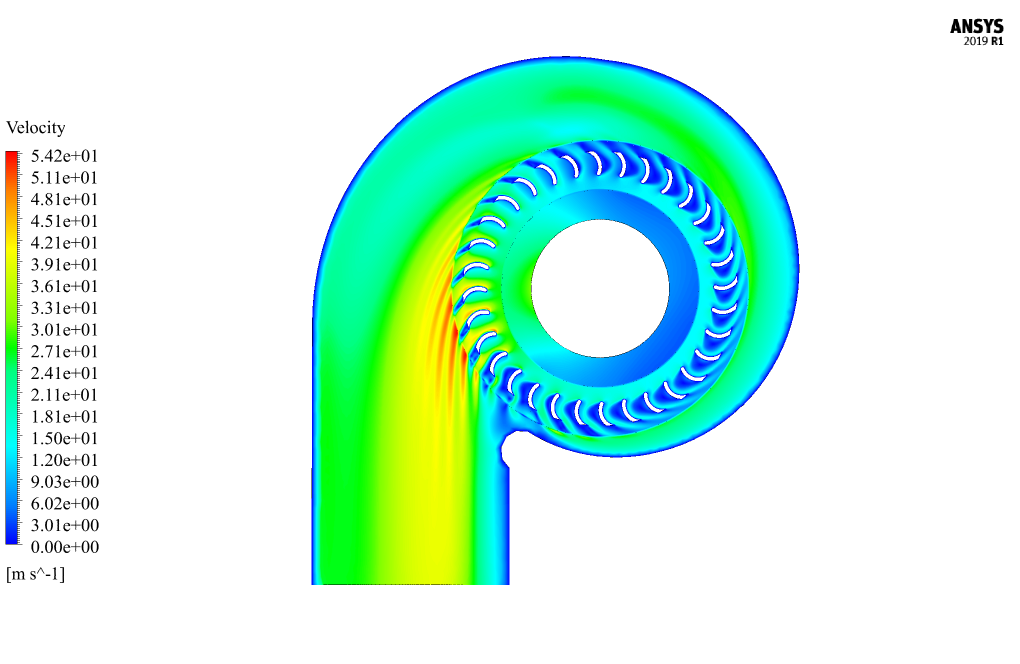
After simulation, two-dimensional contours of pressure, velocity, and turbulence kinetic energy are obtained. Also, two-dimensional pathlines and two-dimensional velocity vectors are obtained.
The results show that the airflow enters the blower’s central part and experiences high-pressure rotational motion in the areas adjacent to the blades. Then the pressure and speed of the airflow increase and are directed outwards from the blower outlet.

Adella McLaughlin V –
I am very impressed with the level of detail in the Centrifugal Blower CFD Simulation tutorial. As someone interested in blower design, this simulation provided insightful data. I’m curious, though, how the software dealt with the transition from the rotating frame of reference in the blade area to the stationary environment. Was it smooth or iterative, and how was this managed within the simulation?
MR CFD Support –
The transition from the rotating frame of reference around the blades to the stationary environment is managed smoothly in ANSYS Fluent through the use of a Multiple Reference Frame (MRF) or sliding mesh model. In the MRF approach, which is likely employed here given the steady-state nature indicated in your description, the software treats the rotating and non-rotating regions as separate but connected, allowing it to calculate the effect of the rotating blades on the stationary parts. This allows Fluent to simulate the rotational flow without physically rotating the mesh, resulting in Fluent iteratively finding a solution that reflects the interactions between the two reference frames.
Esta Mertz –
The tutorial really helped me get my head around how a centrifugal blower works, and seeing the pressure changes in the simulation was eye-opening!
MR CFD Support –
We’re thrilled to hear that the tutorial on the centrifugal blower simulation was so informative and useful for you! Understanding complex systems like blowers is crucial for many engineering projects, and we’re glad that our resources made that process clearer for you. If you need further assistance or have more questions in the future, don’t hesitate to reach out. Thank you for your positive feedback!
Lulu Stracke –
This centrifugal blower simulation was so detailed and engaging! I especially found the method explaining the Frame Motion for rotational flow really enlightening. Thank you for creating such an informative tutorial!
MR CFD Support –
Thank you for your kind words! We are thrilled to hear that you found the centrifugal blower simulation helpful and easy to understand. If you have more questions or need further learning materials, feel free to reach out. We’re always here to enhance your CFD learning experience!
Mona Quigley IV –
The pressure levels achieved by the centrifugal blower wasn’t mentioned in the description. Can you share what pressures we’re talking about here?
MR CFD Support –
In this centrifugal blower simulation, the pressure levels are scenario-specific and depend heavily upon the rotational speed, blade design, and other operational parameters. While I don’t have exact figures from the specific simulation, typical results would include the distribution of static and dynamic pressure within the blower, highlighting regions of high and low pressure generated by the blower’s operation.
Leanne Upton –
This Centrifugal Blower CFD Simulation tutorial has been an incredibly useful resource. It walked me through the process step by step, making complex calculations and the setup seem far more manageable. I appreciated the clarity on defining the rotational domain, and the visual results gave me a clear understanding of air pressure and velocity changes within the blower.
MR CFD Support –
We’re thrilled to hear that you found our Centrifugal Blower CFD Simulation tutorial detailed and easy to follow. Your satisfaction with the clarity of content and the visual results is what we strive for. Thank you for your positive feedback!
Mrs. Daisha Runolfsson DVM –
I am incredibly pleased with how thorough the tutorial for the centrifugal blower simulation was! The step-by-step approach made everything clear, and I could follow along without any confusion.
MR CFD Support –
Thank you so much for the positive feedback! We’re delighted to hear that our tutorial met your needs and provided clarity for your simulation. Your satisfaction is our top priority.
Sandrine Moore –
What impressed me the most is how well the simulation captured the airflow’s transition from low to high pressure as it moves through the centrifugal blower. The attention to detail in the velocity and pressure contours was exceptional.
MR CFD Support –
Thank you for your positive feedback! We’re glad to hear that you are impressed by the accuracy of our CFD simulation and the level of detail in our results. It’s great to know that our efforts to vividly display the airflow’s pressure transition could enhance your understanding of the centrifugal blower’s function. If you have any further questions or need more information, please feel free to reach out.
Dr. Jamal Mann Jr. –
I’m impressed with how the Centrifugal Blower simulation captures the increase in air pressure and velocity. It seems effectively detailed, especially how the rotation affects the airflow dynamics!
MR CFD Support –
Thank you for your review! We are thrilled to hear that you appreciate the complexity and detail of the Centrifugal Blower simulation. It’s always our goal to deliver comprehensive and insightful analysis through our simulations. If you have any further questions or need more assistance, please feel free to reach out.
Muriel Kemmer –
I found the simulation of a Centrifugal Blower to be both enlightening and technically impressive. The detailed explanation of how high-pressure air is directed out shows the robust capabilities of ANSYS Fluent in modelling complex airflow dynamics. Excellent resource for anyone keen on CFD and blower design!
MR CFD Support –
Thank you for the positive feedback on our Centrifugal Blower CFD Simulation tutorial. Your appreciation motivates us to continue providing insightful and technically detailed content for enthusiasts and professionals alike. Keep learning and stay curious!
Nora Dicki –
Just wanted to share how impressed I am with the Centrifugal Blower CFD Simulation tutorial. The step-by-step guidance allowed me to fully understand the setup and I could replicate the results confidently. The visual results were clear and demonstrated the effectiveness of the simulation process—truly a great learning tool for anyone interested in fluid dynamics simulations.
MR CFD Support –
We’re thrilled to hear that our Centrifugal Blower CFD Simulation tutorial met your expectations and provided clear, useful guidance. Thank you for your positive feedback – it’s great to know that our efforts are helping learners like you gain confidence in their CFD analysis skills. If there’s anything else we can assist you with, please don’t hesitate to reach out.
Isadore Davis –
I am thoroughly impressed with how the simulation handles the dynamic behavior of air movement in the centrifugal blower. The detail with which pressure changes and velocity patterns are modeled provides insightful data for practical applications. Well done on creating such an informative and valuable tutorial!
MR CFD Support –
Thank you for taking the time to leave such a positive review! We’re really glad to hear that our tutorial on centrifugal blower simulation has met your expectations and you find the information on pressure and velocity patterns practical and informative. Your feedback is greatly appreciated, and it motivates us to continue delivering high-quality CFD learning materials.
Ignatius Murphy –
What kinds of results are observed from the pressure and velocity contours in this Centrifugal Blower simulation?
MR CFD Support –
In the Centrifugal Blower simulation, pressure and velocity contours reveal how efficiently the device elevates air pressure and velocity. Specifically, more uniform and higher pressure readings near the blower’s output likely indicate effective performance. Conversely, abrupt changes could signal inefficiencies or potentially problematic areas within the blower’s design.
Vern Stroman –
I was thoroughly impressed with the centrifugal blower simulation tutorial! The step-by-step processes were clear, making it easy to follow along. It was particularly interesting to see the transformation of air from low to high pressure, which was well-demonstrated by the contours. The utilization of computational resources via the 2D model was clever as well. Keep up the fantastic work, MR CFD Company!
MR CFD Support –
Thank you for your kind words and positive feedback! We’re delighted to hear that you found the tutorial clear, informative, and easy to understand. It’s great to know that the visuals helped demonstrate the concept effectively. We strive to provide comprehensive and manageable guidance in our tutorials, making CFD analysis accessible for all skill levels. We appreciate your encouragement and look forward to continuing to provide quality learning materials.
Anastasia Gleichner –
Just finished the ‘Centrifugal Blower CFD Simulation by ANSYS Fluent Tutorial’ and was truly amazed by the detailing and precision of the simulation methodology! The step-by-step gave incredibly clear instructions and made understanding the complex physics of blower operation seem straightforward. Plus, the final visualizations of airflow patterns blew me away. Brilliant resource for anyone looking to understand Centrifugal Blowers or improve their simulation skills!
MR CFD Support –
We’re delighted to hear that our Centrifugal Blower CFD Simulation tutorial met your expectations and helped you grasp the complex aspects of blower operations. It’s wonderful to know that the visualizations added value to your learning experience. Thank you for your positive feedback, and we look forward to providing you with more quality learning materials!
Simeon Wisoky –
The tutorial for the centrifugal blower simulation was exceptionally detailed and clear. The sophisticated method used to simulate the rotational flow of air by defining a stationary zone around the blades was clever and must have greatly simplified the process. The clear depiction of pressure and velocity changes as the airflow moves through the blower allowed for easy understanding of the concepts. Can’t wait to apply these techniques to my projects!
MR CFD Support –
Thank you for your positive feedback! We’re glad to hear that our centrifugal blower simulation tutorial was helpful and clearly presented. It’s great to know that you found the method for simulating the rotational flow of air beneficial for your understanding. If you need any further assistance with your projects or have more questions about our tutorials, feel free to reach out. We’re here to help!
Lynn Trantow –
I’m really impressed with the results of the centrifugal blower simulation. The details in the explanation make me appreciate the complexity of the simulation while also making it understandable. Great job showcasing the effects of rotational motion on airflow!
MR CFD Support –
Thank you for your kind words! We’re glad that you found the centrifugal blower simulation comprehensive and informative. It’s our goal to provide detailed and understandable CFD analysis that can be beneficial for everyone interested in the field. If you have any further inquiries or need assistance, feel free to reach out.
Roscoe Fadel –
Your explanation of how air velocity and pressure increase in the blower was excellent!
MR CFD Support –
Thank you for your positive feedback! I am thrilled to hear that the explanations provided in the Centrifugal Blower CFD Simulation by ANSYS Fluent Tutorial were clear and helpful. If you have any more questions or need further assistance, feel free to reach out.
Lavada Pollich –
Is it necessary to simulate the actual rotational movement of the blades, or is the frame motion approach in ANSYS Fluent software enough to capture the air flow accurately in the centrifugal blower?
MR CFD Support –
In many cases, using the frame motion approach to simulate the rotating zone is enough to capture the airflow behavior accurately without having to model the actual rotation of the blower blades. It simplifies the calculations, reducing computational costs while still reflecting realistic performance characteristics of a centrifugal blower in the simulation.