Furnace, Numerical Study, Industrial Application
Original price was: $600.00.$300.00Current price is: $300.00. Student Discount
- The problem numerically simulates Furnace using ANSYS Fluent software.
- We design the 3-D model by the Design Modeler software.
- We Mesh the model by ANSYS Meshing software, and the element number equals 7800000.
- We use the Species Transport model to define the combustion reaction between methane and air.
Click on Add To Cart and obtain the Geometry file, Mesh file, and a Comprehensive ANSYS Fluent Training Video.
To Order Your Project or benefit from a CFD consultation, contact our experts via email ([email protected]), online support tab, or WhatsApp at +44 7443 197273.
There are some Free Products to check our service quality.
If you want the training video in another language instead of English, ask it via [email protected] after you buy the product.
Description
FURNACE
Description
In this project, an industrial Furnace has been simulated, and the simulation results have been investigated using ANSYS Fluent software. We perform this CFD project and investigate it by CFD analysis.
In this project, Ansys Fluent software stimulated an industrial Furnace numerically. The furnace simulated in this project is combusted with methane fuel to heat the Methane in the pipes so that the Methane can be moved more quickly and with less force.
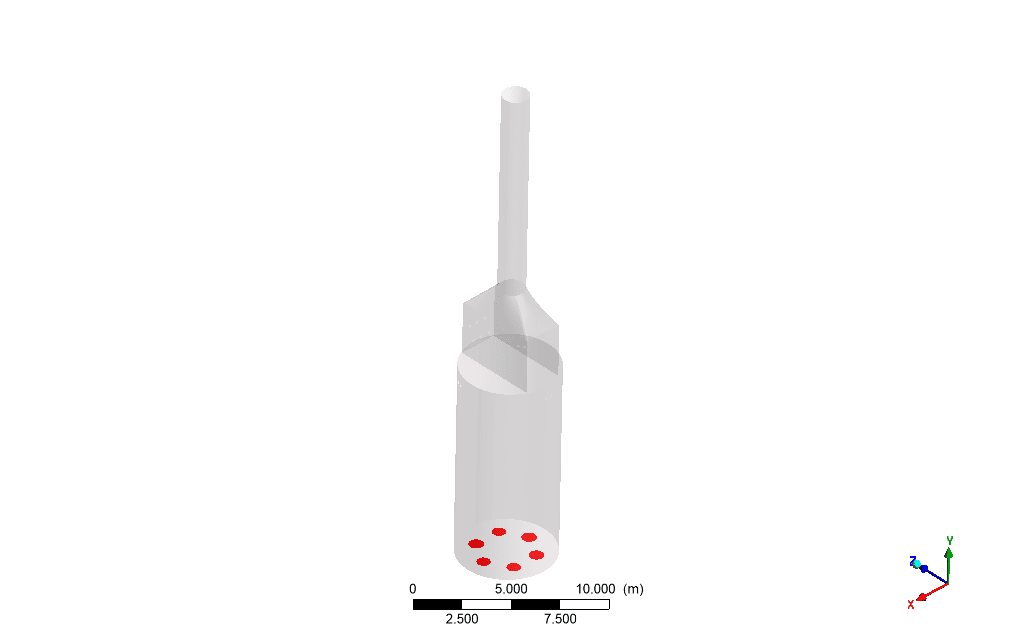
By observing the results, it can be seen that the outlet temperature of methane pipes has increased compared to the inlet temperature. The fuel enters and is mixed with the air inside the furnace, and combustion occurs. Six burners are installed on the floor of the furnace.
The flame hits the pipes inside the furnace in the radiant section and causes heating of the liquid inside the pipe, Methane. Combustion gases are released from the chimney as burnt gases.
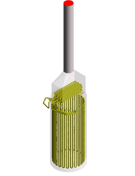
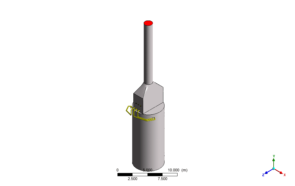
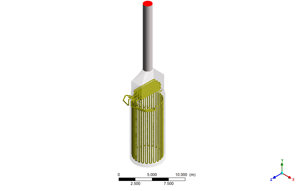
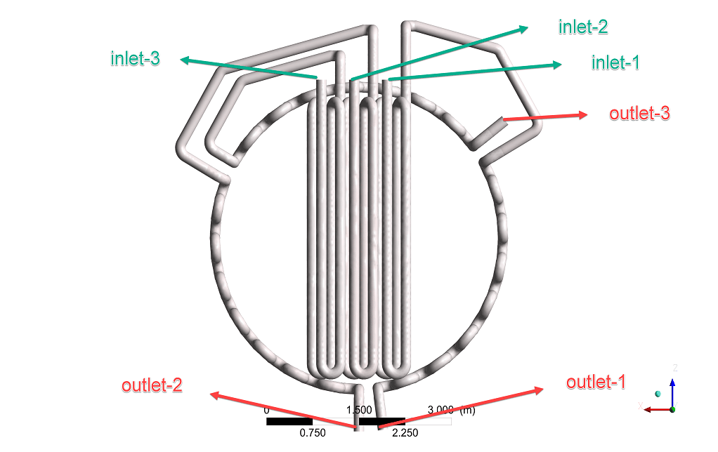
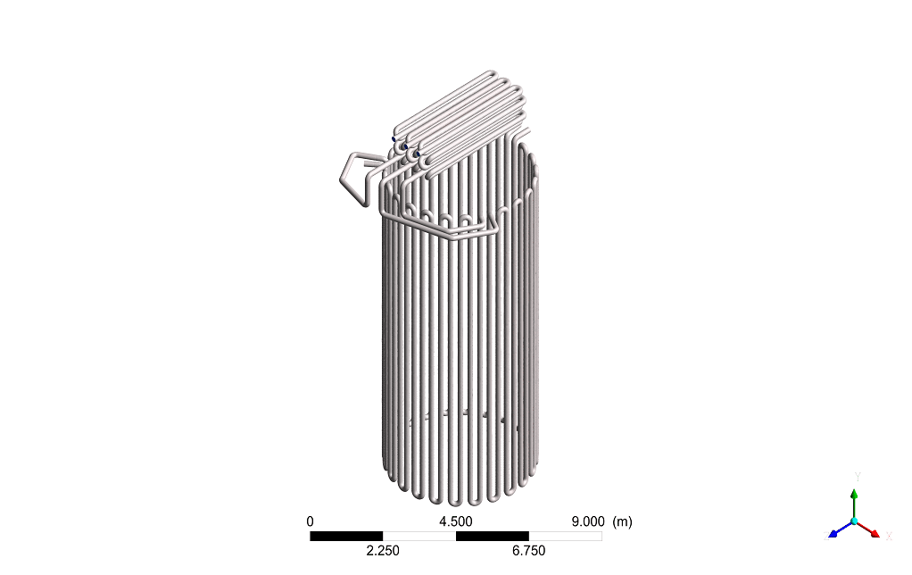
We designed the geometry of the present work by SolidWorks software (drawing pipes) and the rest of the geometry by Design Modeler software, which has the exact dimensions as the model in the attached catalog.
Purpose:
Furnaces are used in oil, gas, and petrochemical industries to provide heat for various processes over 400 c.
To move heavy mineral flood oil, it is often necessary to reduce the viscosity to facilitate this operation by heating the oil in the furnace. The purpose of this project is to increase the temperature of Methane.
Abstract:
In this project, ANSYS Fluent software stimulated an industrial Furnace numerically. The furnace simulated in this project is combusted with methane fuel to heat the Methane in the pipes so that the Methane can be moved more quickly and with less force. By observing the results, it can be seen that the outlet temperature of methane pipes has increased compared to the inlet temperature.
Introduction to Furnace Industrial Application:
Oil is one of the precious gifts that nature has given to humans. The impact of oil cannot be ignored in humanity’s economic, political, and social spheres. Oil as an essential element has contributed to economic development, employment, and peace.
Therefore, one of the major challenges in the oil industry is the displacement of it or its products in transmission lines, which is difficult to move in the pipeline due to the high viscosity. Therefore, by heating the desired fluid, the displacement in the tube is better due to the reduction of viscosity.
Furnaces, like other equipment, have an evolutionary course and with the advancement of engineering knowledge, their efficiency and safety have been increased day by day with new designs. Increasing the efficiency as much as possible, improving the safety, simplification, guidance, and the ability to use different fuels in the furnaces are among the intellectual preoccupations of the engineers in designing and manufacturing different types of furnaces.
How the Device Works:
The fuel enters and is mixed with the air inside the furnace, and combustion occurs. Six burners are installed on the floor of the furnace. The flame hits the pipes inside the furnace in the radiant section and causes heating of the liquid inside the pipe, Methane. Combustion gases are released from the chimney as burnt gases.
Furnace Simulation
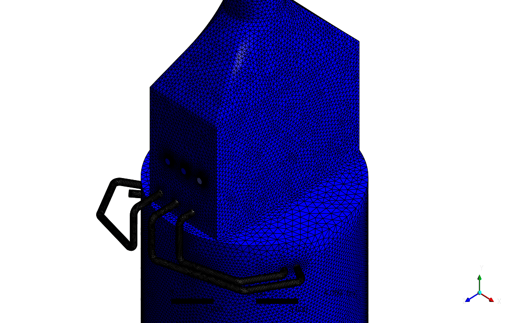
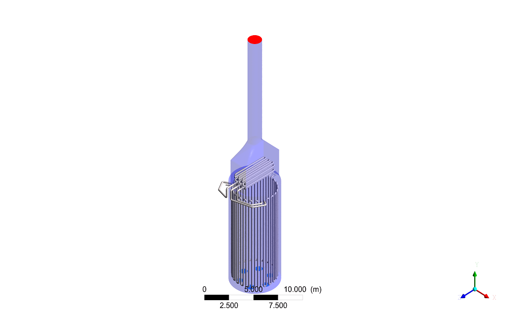
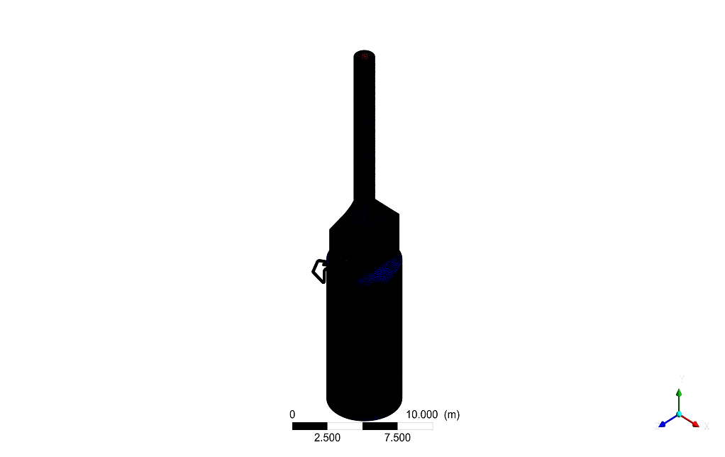
We designed the geometry of the present work by SolidWorks software (drawing pipes) and the rest of the geometry by Design Modeler software, which has the exact dimensions as the model in the attached catalog. The meshing of this present model has been generated by ANSYS Meshing software. The mesh grid is structured, and the total cell number is more than 7800000.
FURNACE simulations are performed with a steady-state solver with the energy equation, and the k-ε model is Realizable as the turbulence model. In addition, species equations are active. The fluids used in this simulation are Methane and air for the continuous phase. Coupling of velocity and pressure equations is also performed using the SIMPLE algorithm by ANSYS Fluent software.
Geometry
Mesh
FURNACE Result:
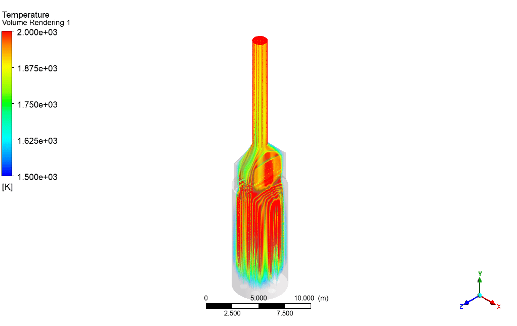
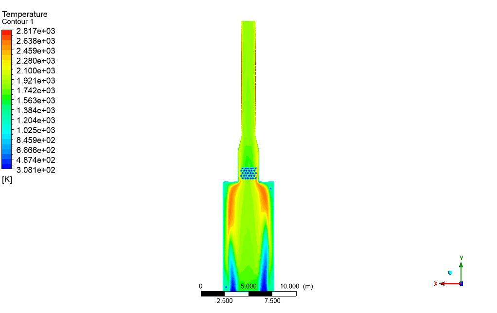
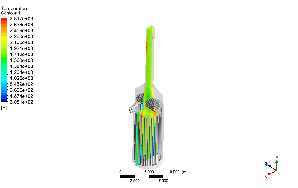
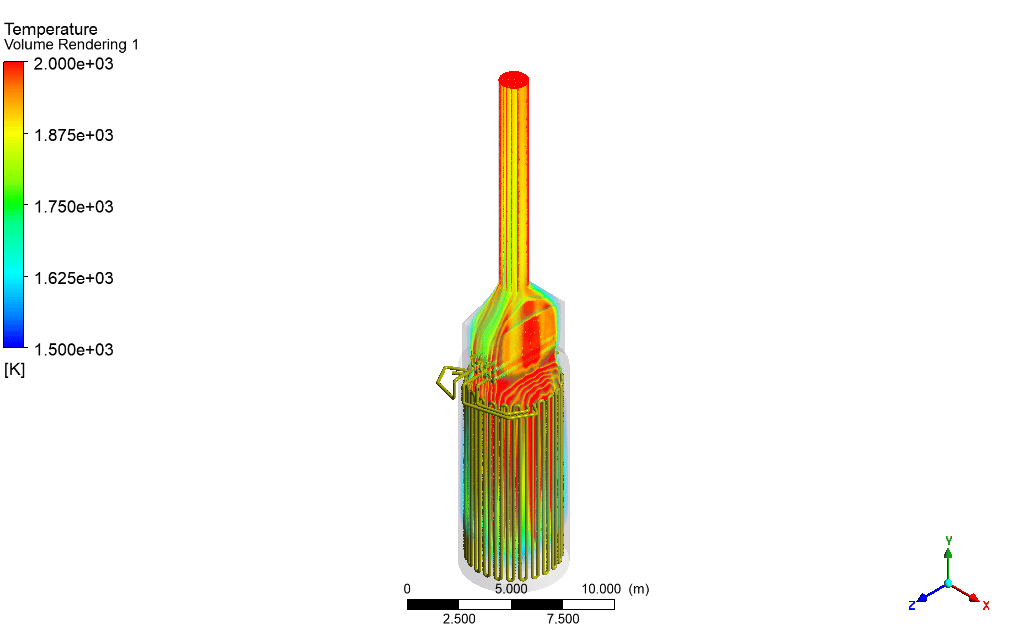
According to the obtained results, it is observed that a suitable flame has been formed, and also, the outlet temperature of the pipes has significantly increased compared to the inlet.
| The outlet temperature (k) | The inlet temperature (k) | zone |
| 2992.7241 | – | Furnace |
| 4596.063 | 305.65 | Pipe1 |
| 4613.5067 | 305.65 | Pipe2 |
| 4619.3487 | 305.65 | Pipe3 |
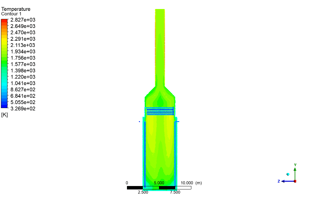
Temperature Contour
Attachment:
Geometry (inlet flame)
Geometry
Geometry
Geometry(pipes)
Geometry(pipes)
Mesh
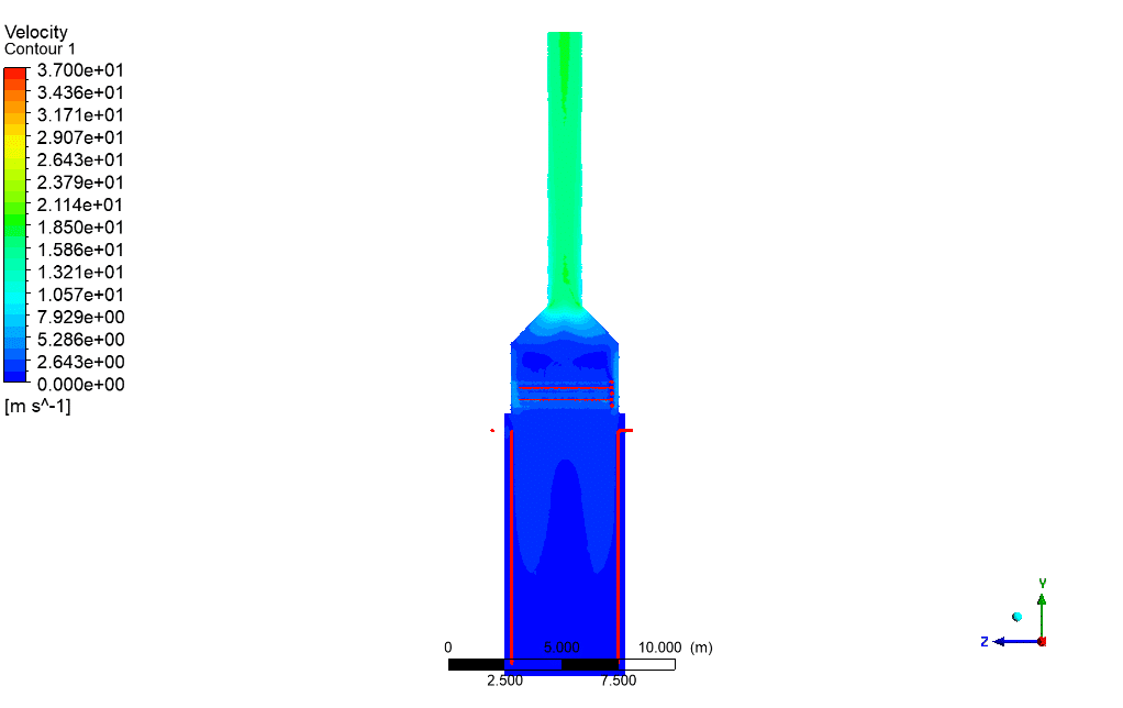
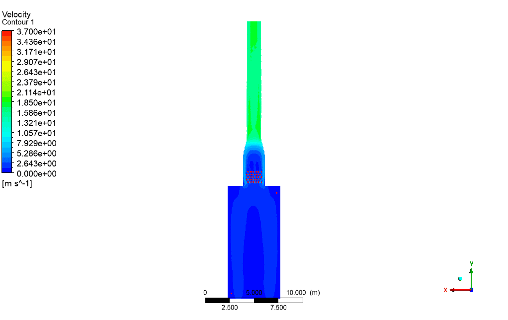
velocity Contour
velocity Contour
Temperature Contour
Temperature Contour
Temperature Contour
Temperature Contour
Temperature Contour
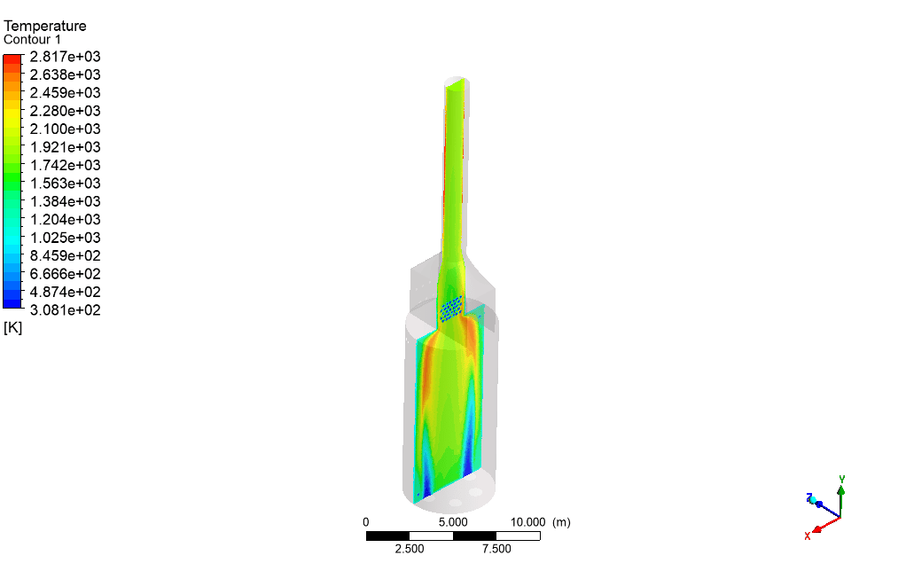
Temperature Contour(3D)
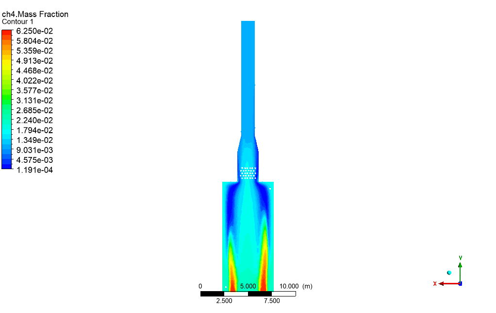
Mass fraction of ch4
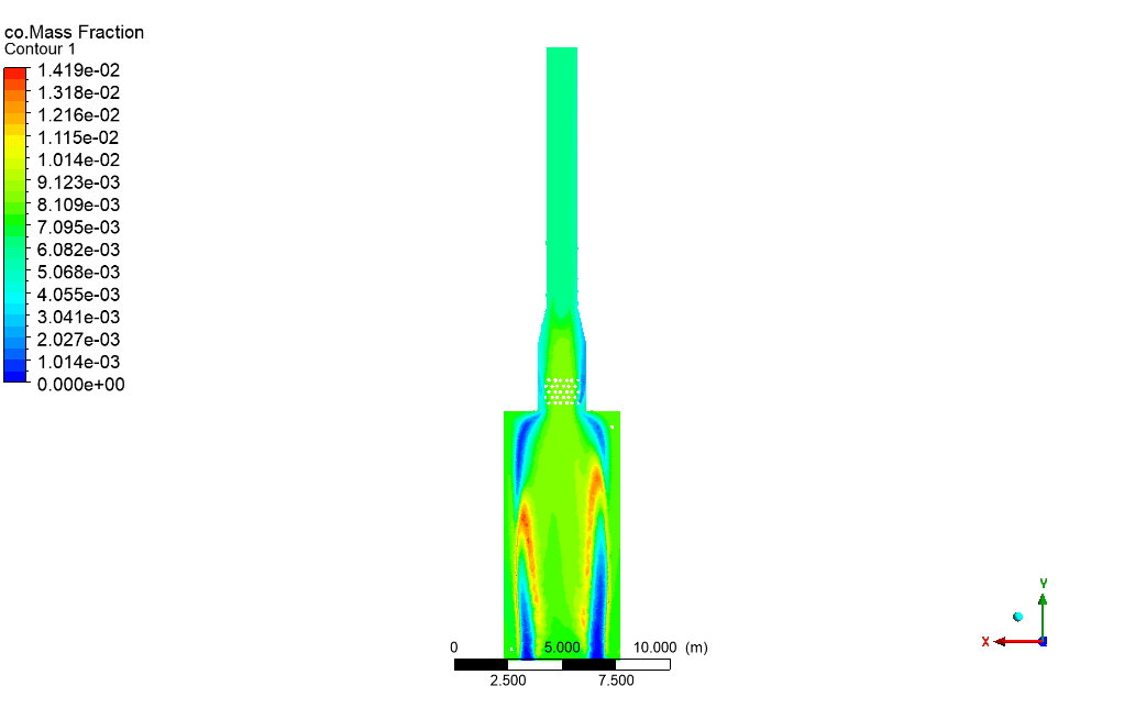
Mass fraction of co
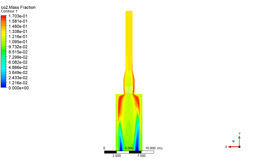
Mass fraction of co2
Mass fraction of h2o
Mass fraction of o2







Mikel Harvey –
I completed the Furnace CFD simulation tutorial and the results were awesome. The visualizations really helped me understand how temperature and gas composition change through the furnace. Excellent work on creating such a detailed and practical learning tool.
MR CFD Support –
Thank you for your positive feedback! We’re very glad to hear that the simulation and its visualizations helped enhance your understanding. It’s great to know you found the tutorial both detailed and useful. We appreciate your appreciation and look forward to providing you with more valuable learning resources in the future!
Kayley Barrows –
The topic of furnace efficiency is fascinating, and I’m genuinely impressed by the simulation project! For a user considering this product, could you tell me what metric efficiencies were achieved, if discussed, or is it mainly focused on the temperature rise from inlet to outlet?
MR CFD Support –
The product primarily showcases the temperature rise from the inlet to the outlet as an indicator of the furnace’s performance rather than delineating specific metrics of efficiency. Detailed temperature contours provided in the results facilitate understanding the effectiveness of the heat transfer process within the furnace.
Tristin Schowalter –
Can I simulate a similar furnace with a different fuel type, using the procedure described in this project, and what changes to the setup might be needed if I switch from methane to, say, propane?
MR CFD Support –
Certainly! The methodology and procedure described in this project for methane can be adapted for simulating a furnace with propane fuel. You’ll need to adjust the material properties for propane fuel, update the combustion and species model parameters in ANSYS Fluent, and revalidate your boundary conditions to ensure accuracy. The core steps in geometry creation, meshing, and simulation setup would remain the same.
Wilson Wyman –
I’ve successfully used the data in the Temperature Contour attachments from your product for a report. The details in the contours made understanding heat distribution very clear. Thank you!
MR CFD Support –
We are so pleased to hear that the Temperature Contours were helpful in your report and provided clear insights into heat distribution. Thank you for sharing your positive experience with our product. Your satisfaction is our top priority, and if there’s anything else we can do to assist your further, please don’t hesitate to reach out to us!
Otilia VonRueden –
Fantastic learning product by MR CFD! Using this Furnace simulation project helped me get a practical understanding of the combustion process and the effects of heating on methane fluid dynamics. The detailed steps in combining SolidWorks and Design Modeler for designing and the ANSYS platform for simulating were enlightening. I especially appreciate the complexity of creating a structured mesh with over 7 million cells. The results clearly showed an increase in outlet temperature which enhances my confidence in employing such simulations in real-world applications. Cheers to MR CFD for an exceptional educational experience!
MR CFD Support –
Thank you so much for taking the time to leave us such a wonderful review! We are thrilled to hear that you found the simulation project educational and useful. It’s great to know that our detailed instructions and the complexity of the project were able to contribute to your understanding of industrial furnace applications. If you ever have more questions or need further insights into such CFD analyses, don’t hesitate to reach out. Your satisfaction is very important to us, and we look forward to assisting you in your future learning endeavors. Thanks again for using our learning product!
Lurline Bergstrom –
I’m impressed by the detail put into this simulation for the furnace using ANSYS Fluent. The increase in the outlet temperature of methane pipes following heating is nicely demonstrated, reflecting the project goal for improved Methane movement. The use of geometric tools like SolidWorks and Design Modeler software to precisely replicate the model as per catalog guidelines shows thoroughness and precision. The meshing strategy’s attention to cell number and structure highlights a focus on obtaining accurate simulation results. The steady-state solver, along with the Realizable k-ε model for turbulence and species equations for Methane and air, speak to a sophisticated approach to capturing the necessary physics in this industrial application. It’s especially reassuring to see the use of the SIMPLE algorithm for the coupling pressure and velocity equations, ensuring robust and convergent solutions. Well done on achieving such a complex CFD analysis with useful insights for the oil, gas, and petrochemical industries.
MR CFD Support –
Thank you for the complimentary review of our Furnace CFD simulation project! We are delighted to hear you appreciated the detail, precision, and technical depth of our analysis. Receiving feedback from engaged and informed customers like you reaffirms our commitment to delivering high-quality, well-documented, and practical simulation insights. Your recognition of our comprehensive and precise approach motivates us to further enhance our services for our clients’ diverse and challenging industrial applications.
Domenick Lang Jr. –
This learning material on furnace simulations in industrial applications sounds comprehensive and detailed. Well-presented outcomes and the temperature increase in methane pipes is indicative of an effective system design. Kudos on clearly depicting the combustion process and temperature contours in your result section.
MR CFD Support –
Thank you for your positive feedback on the Furnace simulation project. We are pleased to hear that you found the material detailed and the results informative. It’s our goal to deliver high-quality learning experiences that are both comprehensive and practical. If you ever have any questions or need further assistance with our products, please don’t hesitate to reach out.
Myra Dibbert –
Can I use this furnace simulation learning material to model my own furnace design? Will the parameters be adjustable to match different sizing and burning materials?
MR CFD Support –
Absolutely, you can utilize this learning material to model your own furnace design. The projects are set up in such a way that you can adjust most parameters including size, fuel type, and operational conditions to match the specifications of your design.
Mr. Simeon Casper II –
Fascinated with the detail in the simulation of the industrial furnace using ANSYS Fluent. It has given me deep insights into combustion processes and the efficiency of heating elements in real-life applications. The application of design and CFD tools to optimize performance is admirable, and I’ve learned a lot from the results, especially the temperature distributions which clearly indicate effective heating. The simulation’s capacity to iterate towards an efficient furnace design for oil and gas applications can significantly contribute to the industry’s cost and energy savings. Great job to the team for such a comprehensive study!
MR CFD Support –
Thank you for your thoughtful review! We’re delighted to hear that the Furnace simulation project has provided you with valuable insights into furnace design and performance. It’s always our goal to deliver comprehensive and practical CFD solutions that can be applied to improve real-life engineering processes. Your appreciation motivates us to continue delivering high-quality simulations. If you have any inquiries or need further assistance, don’t hesitate to reach out to us.
Jennyfer Donnelly –
The analysis of methane combustion in the furnace is fascinating. Could you please explain how the temperature distribution within the furnace was verified to be accurate?
MR CFD Support –
To ensure the accuracy of the temperature distribution within the furnace, we used several verification techniques. The simulation results were compared with empirical data and theoretical values when available. Also, mesh independence tests were performed to ensure that the number and distribution of computational cells are sufficient to capture the thermal gradients correctly. Additionally, the model was calibrated using temperature readings from specific locations within the furnace, where available, to match the physical process as closely as possible.
Lee Maggio III –
What an impressive simulation! The work carried out on this industrial furnace and the meticulous CFD analysis contributes significantly to understanding combustion processes and facility optimization. I’m genuinely impressed by the attention to detail from the geometry modeling to the final temperature contour results. Great application of theory to a real-world, practical scenario!
MR CFD Support –
We appreciate the time you took to write such a positive review. It’s our aim to deliver comprehensive CFD simulations that offer valuable insights into complex systems like industrial furnaces. We are thrilled to know that the work on the Furnace simulation project met your high standards and satisfaction. Thank you for recognizing the effort and precision our team has invested. If you have any more feedback or need further assistance, please let us know!
Korey Rodriguez Jr. –
I’ve always been intrigued by CFD analysis of complex systems. In this furnace simulation, how did the incorporation of different burners on the floor of the furnace impact the uniformity of heating and the methane movement inside the pipes?
MR CFD Support –
In the simulation, the presence of multiple burners installed on the furnace floor allows for a more even distribution of heat. This arrangement ensures that the flame directly hits the pipes in the radiant section, providing consistent heating of the liquid methane inside the pipes. As a result, the uniformity of the furnace’s heating process enhances the effectiveness of the methane movement by reducing its viscosity through the increase in temperature, evidenced by the significant rise in outlet temperatures compared to the inlet.
Amya Skiles DVM –
The project looks incredibly comprehensive. Particularly impressive is the detailed temperature change in the Methane from inlet to outlet. Most interesting is the ability to effectively simulate a furnace environment and analyze temperature and gas concentrations, it’s obvious that a lot of work went into not just the physical design but the analytical aspects as well.
MR CFD Support –
Thank you for the positive feedback! We’re glad to hear that our efforts in simulating the industrial furnace and presenting detailed temperature analysis have been well-received. Our team is dedicated to providing intricate designs along with thorough analysis to ensure our simulations are valuable. We truly appreciate your recognition and are here for any further information or inquiries!
Mr. Ruben Stoltenberg Sr. –
Amazing details and depth in the simulation of the furnace! It’s great to see such an accurate representation of the industrial process with methane combustion. The clear increase in methane outlet temperature demonstrates a successful simulation in facilitating pipe flow. Great work!
MR CFD Support –
Thank you for your kind words and appreciation! We’re glad to hear that the simulation met your expectations and provided valuable insights into the industrial furnace combustion process.
Robyn Steuber –
This course sounds fascinating! Is it suitable for beginners, or should I have a strong background in ANSYS Fluent before attempting it?
MR CFD Support –
The product you’re referring to seems to cover advanced topics in computational fluid dynamics using ANSYS Fluent. While it does include comprehensive content, it might be better suited for individuals who have some foundational understanding of CFD principles and basic familiarity with ANSYS Fluent software. If you’re a beginner, we recommend starting with introductory courses to build up your knowledge before tackling complex simulations like an industrial furnace.
Sarah Hermiston –
I was impressed by how the simulation allowed for very clear observations of temperature changes and flame formation. The resulting increase in pipeline temperatures to effectively reduce the viscosity of Methane for transport clearly showed the utility of the project. Excellent use of computational analysis to aid in industrial applications!
MR CFD Support –
Thank you for your thoughtful review! We’re delighted to know that our product lived up to your expectations and that the results provided clear and useful insights into the performance of an industrial furnace. It’s great to hear that the CFD simulation was helpful in understanding the process of viscosity reduction in Methane transport. We aim to provide valuable tools for professional and educational growth, so your feedback is truly appreciated!
Ms. Rosalind Koss DDS –
I’m quite impressed with the level of detail in the CFD simulation of the furnace. Can you explain how the temperature increase in the Methane pipes was validated or compared to experimental or real-world results to ensure accuracy of the simulation?
MR CFD Support –
Thank you for your positive feedback! To ensure accuracy of the simulation, the temperature increase within the Methane pipes is typically validated by comparing the CFD results to empirical data collected from physical experiments or operational furnaces with similar conditions. This comparison helps validate whether the simulation accurately predicts the thermal behavior under the specific operating conditions applied in the numerical study.
Prof. Gus Lemke Sr. –
The level of detail in your simulation of the industrial furnace is impressive. It is fascinating to see how you utilized ANSYS Fluent to accurately model heat distribution and fuel combustion to increase methane’s temperature which is critical for industrial processes demanding precise thermal management. Great job capturing the behavior of methane and the efficiency of the furnace!
MR CFD Support –
Thank you for your kind words! We are thrilled to hear that our simulation met your expectations and provided insight into the critical aspects of industrial furnace operation. Your feedback is greatly appreciated and helps us strive for continuous improvement in our CFD products. If there’s anything else you’re curious about or other ways we can assist you, please let us know!