Golf ball Aerodynamics, ANSYS Fluent CFD Simulation Training
Free
In this project, a golf ball is studied aerodynamically, at speed with lateral angle and zero degree angle of attack using ANSYS Fluent software.
Click on Add To Cart and obtain the Geometry file, Mesh file, and a Comprehensive ANSYS Fluent Training Video.
To Order Your Project or benefit from a CFD consultation, contact our experts via email ([email protected]), online support tab, or WhatsApp at +44 7443 197273.
There are some Free Products to check our service quality.
If you want the training video in another language instead of English, ask it via [email protected] after you buy the product.
Description
Problem Description
In this project, a golf ball with dimples and a similar sphere without dimple are studied aerodynamically, at speed with lateral angle and zero degree angle of attack using ANSYS Fluent software. The intended speed is 94 meters per second.
Introduction
In the dynamic simulation, quasi-experimental aerodynamic coefficients are used. These coefficients are obtained by quasi-experimental software. The coefficients obtained in these softwares have many errors. To achieve more accurate coefficients, numerical simulation by computational fluid dynamics is used, and the coefficients obtained by semi-experimental simulation software are calibrated using CFD coefficients. In this research, the calculation of aerodynamic coefficients has been done using numerical simulations and Fluent commercial software.
Golf Ball Geometry & Mesh
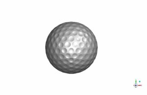
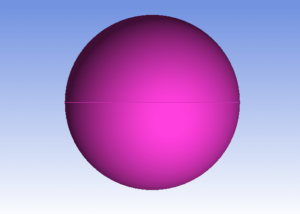
In this section, the geometry of the golf ball and spherical ball without dimple and the grid on it are examined.
One of the most influential and time-consuming steps in numerical simulations, is grid generation. The better mesh quality, make other solving steps to proceed more accurately. Due to the dimensions of the problem and the car’s geometry, the prism grid has been used for the boundary layer, and the unstructured grid has been used for other parts of the solution domain. To generate a mesh in ICEM software, you must first determine the size of the mesh elements in different parts according to the dimensions of the problem and the type of flow and geometry of the object under study. Various methods have been proposed to create an unstructured mesh in ICEM software. This software has two top-down and bottom-up methods for generating a UNS mesh. Below, we introduce these two methods.
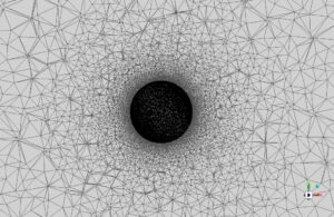
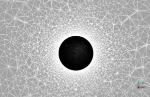
To create a suitable mesh, the combined (hybrid) method is used so that the whole solution domain, including surfaces and lines, is meshed with the help of the Octree method. Then with the help of the Delauney method and with the help of the existing mesh, a smooth mesh is created in the whole solution domain. The following figure shows the grid on the middle page:
The mesh is fragmented in parts of the geometry where the radius changes abruptly, and on the fractures and dimples, it is larger in other areas.
Solution Settings
We investigate the issue numerically, using Fluent commercial software, and solve this problem in Steady mode using the pressure-base method. Also, we use Fluent software to solve the governing equations numerically. In this chapter, we consider flow conditions, type of boundaries, type of solvent, and flow discretization methods..
Fluid Properties
In this research, the fluid is air. The following table shows the air properties extracted from the Fluent software database, given that the current is in an incompressible regime and its density is constant.
| Amount (units) | Fluid Properties(air) |
| 1006.43 (J/kg.K) | Thermal pressure coefficient |
| 0.0242(w/m.k) | Thermal conductivity |
Boundary Conditions (Golf Ball)
One of the most influential variables in the numerical solution process is boundary conditions. For this purpose, we use different boundary conditions in the computational range. We introduce these conditions as:
- wall
- velocity inlet
- pressure outlet
-
models (car) K-epsilon viscous model realizable K-epsilon model Near wall treatment Standard wall function boundary conditions (car) velocity inlet inlet 94 m/s velocity magnitude (m/s) pressure outlet outlet 0 Pascal gauge pressure wall wall of body stationary wall wall motion solution methods (car) couple pressure velocity coupling second order pressure spatial discretization second order upwind momentum first order upwind turbulent kinetic energy first order upwind turbulent dissipation rate initialization (car) standard initialization method 0 (Pa) gauge pressure 94 (m/s) x-velocity 0 (m/s) y-velocity , z-velocity
Convergence
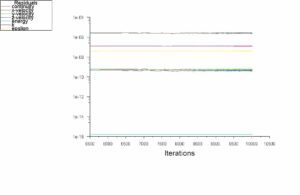
In computational fluid dynamics, We use iterative solutions to achieve the answer to the problem. These iterative solutions start by taking the initial values and continue solving until they reach the convergence criterion or the number of steps specified by the user. We define different criteria for the convergence of the problem. One of the most widely used criteria for determining the convergence of a problem is residual values. Residuals are the sum of the values calculated on all cells in the current and previous time steps. They are calculated in each iteration, and the solution continues until its value is less than the criterion specified by the user. It is usually recommended to reduce the residual values by 3 or 4 orders. We can see in the figure below, all residuals, including velocities and parameters of the perturbation model, are smaller than 10e-3.
Results & Discussions (Golf Ball)
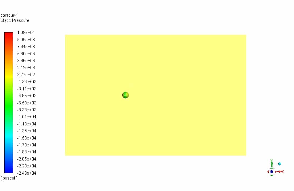
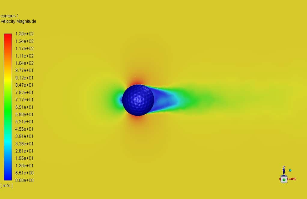
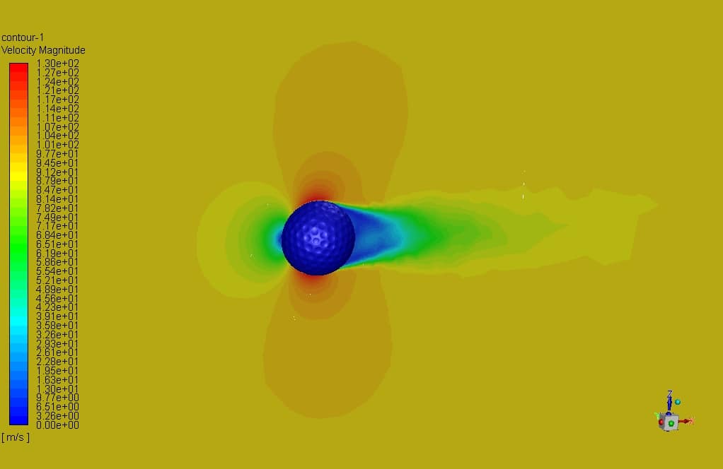
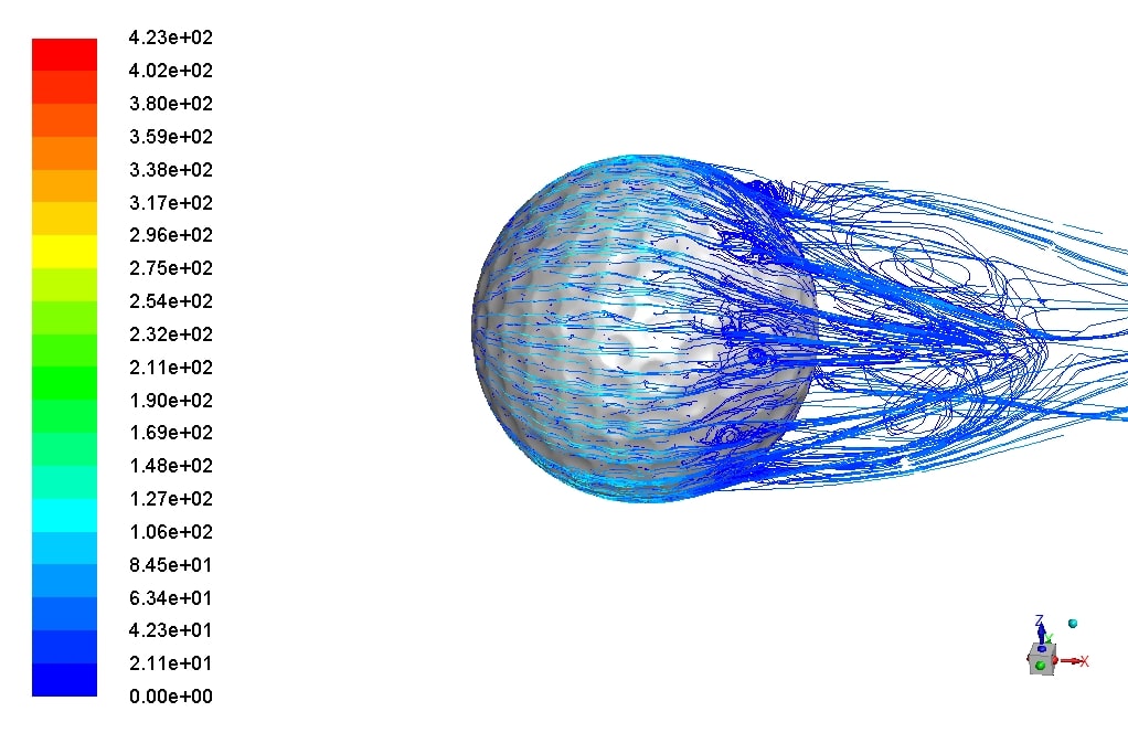
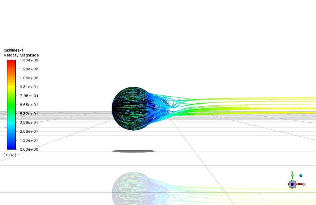
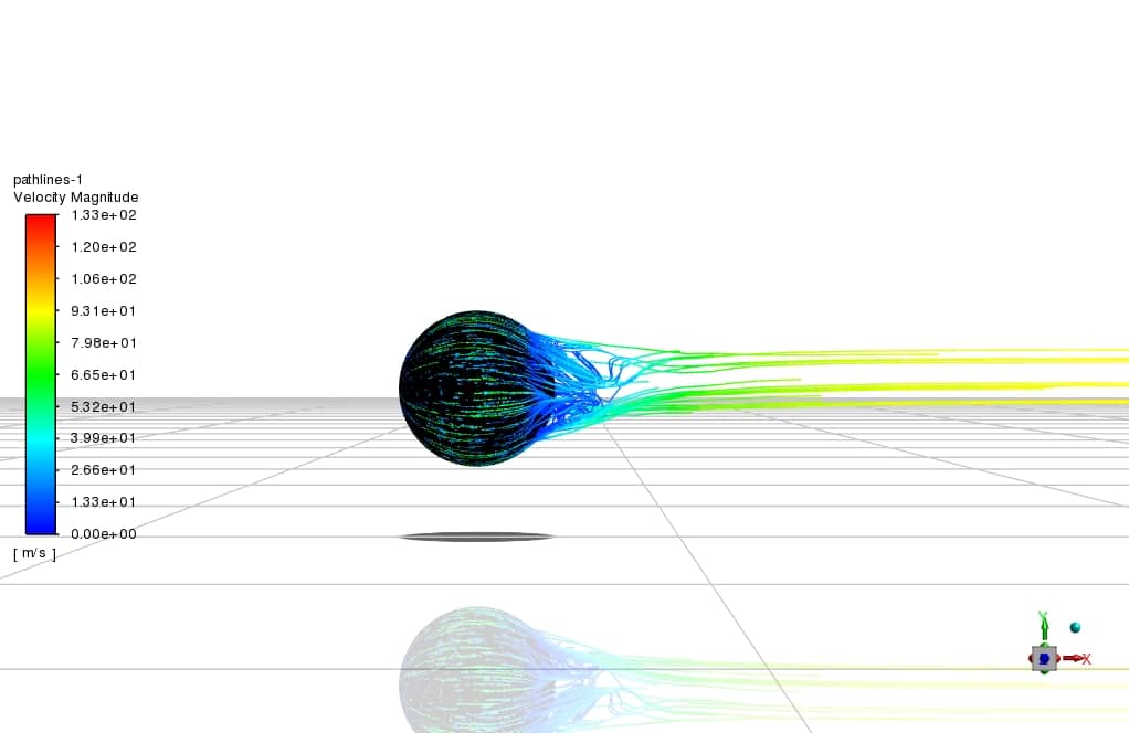
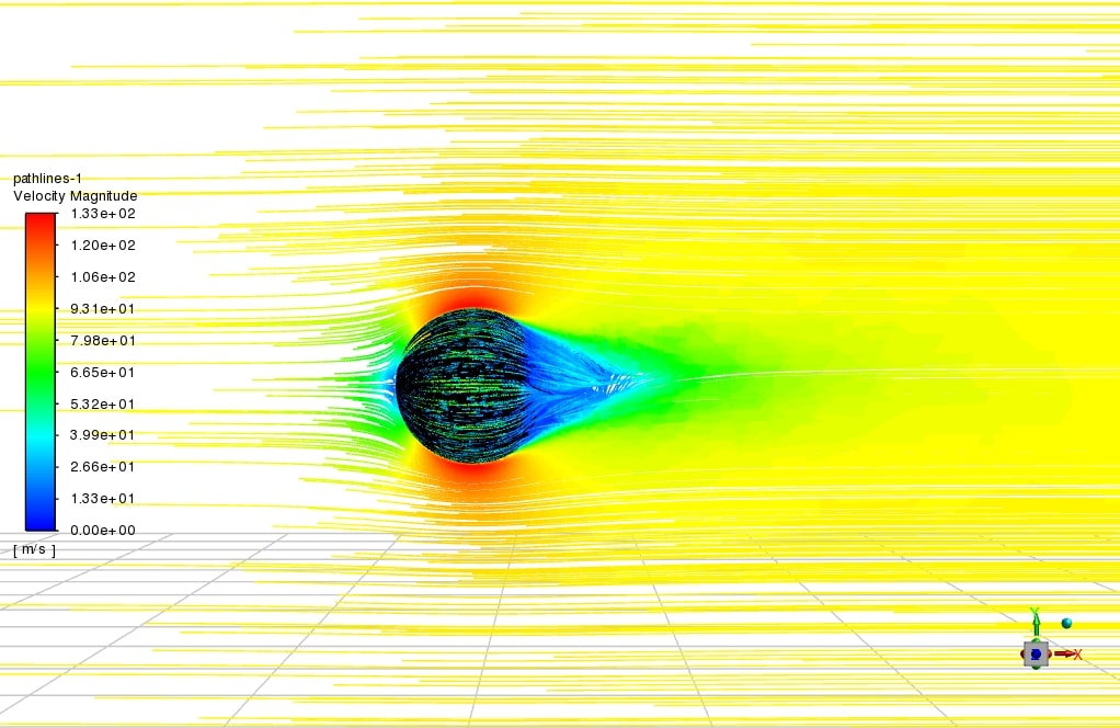
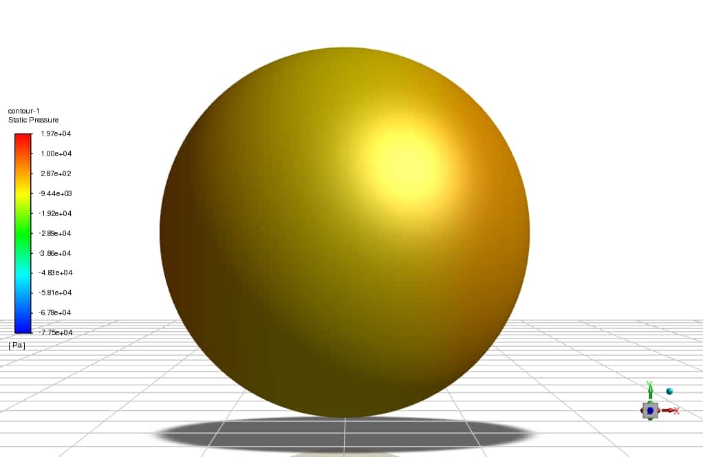
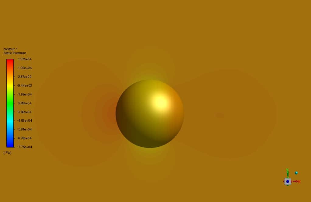
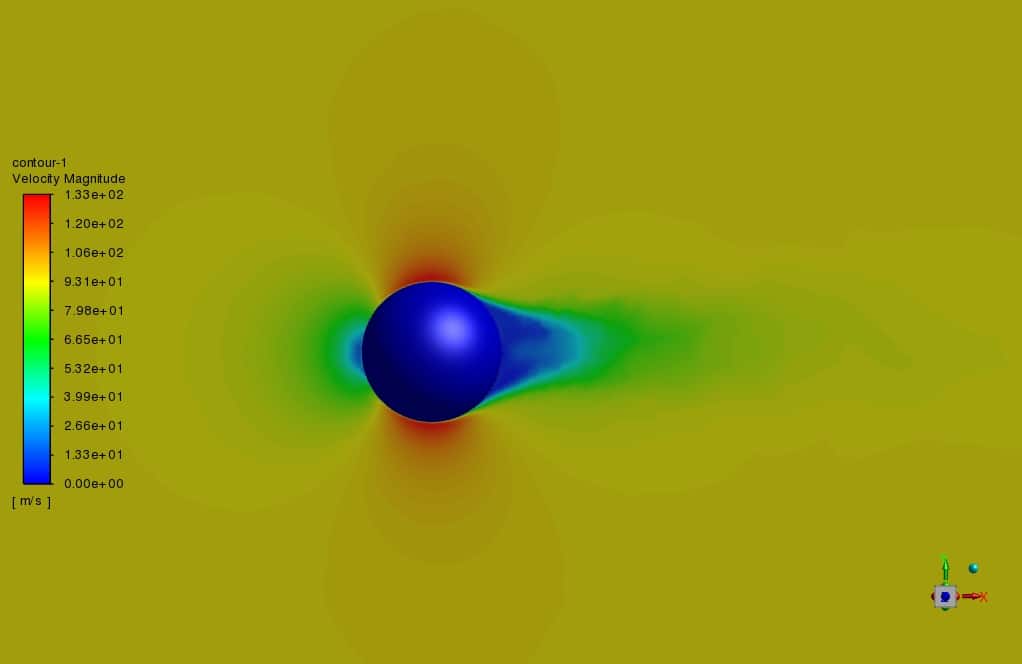
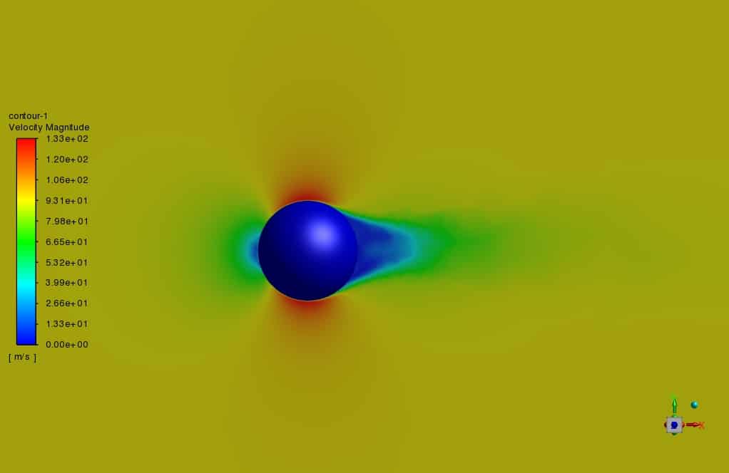
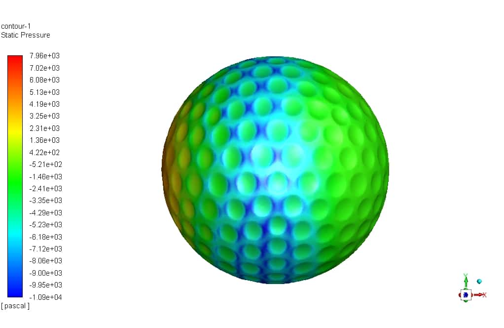
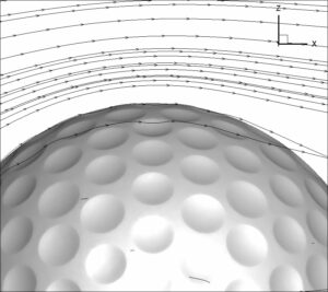
In this chapter, we present the results related to simulation and analyzed qualitatively. The quality of the flow around the Golf ball body has been studied using boundary diagrams. The figure below shows the dimples and pathlines on the golf ball.
The results show that the roughness of the sphere and the depressions (dimple) on the golf ball at relatively high Reynolds numbers increase the momentum on the surface and the turbulence in the boundary layer and delay the flow separation, which reduces the drag force. But at low Reynolds numbers in layered flow, the flow separates from the surface, and the drag coefficients for both smooth balls and golf balls are very close to each other.
You can obtain Geometry & Mesh file and a comprehensive Training Movie that presents how to solve the problem and extract all desired results.



Dion Frami III –
Absolutely loved the detail in the Golf Ball CFD Simulation training! The step-by-step approach on handling the complex aerodynamics of a golf ball was incredible. Anxious tip of the cap to MR CFD for such an immersive learning experience.
MR CFD Support –
Thank you for your kind words! We’re thrilled to hear that our Golf Ball Aerodynamics CFD Simulation training met your expectations and provided you with a comprehensive understanding of the topic. Your enthusiasm for the material is just what we strive for!
Mittie Lowe –
I’m really impressed with how the study compares a golf ball with dimples to a smooth sphere in terms of aerodynamics. The use of CFD to calibrate aerodynamic coefficients sounds fascinating. The intricate details of mesh generation were particularly informative.
MR CFD Support –
Thank you for your positive feedback! We’re delighted to hear that you found the comparison insightful and the details on mesh generation informative. Detailed CFD studies like these play a crucial role in understanding complex aerodynamic behavior, and we’re glad that our training was able to convey these concepts effectively. We appreciate you taking the time to review our product.
Caleb Ankunding I –
The golf ball CFD simulation sounds comprehensive, but can you elaborate on how the surface roughness and dimples influence the drag coefficients at different Reynolds numbers?
MR CFD Support –
In this simulation, the surface roughness and dimples on the golf ball increase turbulence within the boundary layer, which means that at higher Reynolds numbers, the boundary layer can adhere to the ball’s surface for a longer distance before separating. This delayed separation minimizes the wake behind the ball, thereby reducing the drag force. At lower Reynolds numbers with laminar flow, the impact of dimples is less pronounced, and the drag coefficients for smooth spheres and dimpled golf balls are much closer.
Nick Goodwin –
The training was amazing! The visualization of the golf ball’s dimples and pathlines provided a clear understanding of the aerodynamics involved. It was truly enlightening to see how the dimples play a crucial role in reducing drag and altering the flight path. Highly recommended for any engineering or sports enthusiast interested in the physics of golf.
MR CFD Support –
Thank you for your upbeat review! We’re thrilled to learn that our training materials provided you with a clear and thorough understanding of the golf ball aerodynamics. It’s always wonderful to hear when our efforts to create insightful visualizations have a positive impact. Your recommendation is much appreciated, and we hope you’ll find more of our products equally enlightening!
Kaya Grimes –
I’m truly impressed with the attention to detail in the Golf ball Aerodynamics simulation training! It clarified many concepts for me.
MR CFD Support –
Thank you so much for your kind words! We’re thrilled to hear that the Golf ball Aerodynamics simulation training was helpful for you. It’s our pleasure to provide high-quality learning materials that enhance understanding. If you need any further assistance or have more questions, feel free to reach out!
Fredy Turcotte –
The course provided clarity on golf ball aerodynamics and the influence dimples have on drag force. Very impressed by the level of detail in the mesh generation and the easy-to-follow solution settings explanations!
MR CFD Support –
Thank you for your positive feedback! We’re pleased to hear the training provided you with insight into the aerodynamics of golf balls and that the sections on mesh generation and solution settings were particularly helpful. Should you have any further inquiries or require additional support as you apply these concepts, don’t hesitate to reach out.
Jacklyn Hayes –
This training for simulating the aerodynamics of a golf ball was detailed and very helpful. The inclusion of a smooth sphere as a comparison to the dimpled golf ball provided an excellent reference for understanding the impact of dimples on aerodynamics at different speeds.
MR CFD Support –
Thank you for your positive feedback! We’re thrilled to hear that our CFD simulation training on golf ball aerodynamics was beneficial for you and that the comparative approach enhanced your understanding. It’s great to know that our product met your expectations. If there’s anything more you’d like to learn about or need further assistance with, don’t hesitate to get in touch!
Jimmy Dupuis –
Intresting project.
My thanks and appreciation.
Jimmy Dupuis –
Interesting project.
My thanks and appreciation.
Lydia P. –
So this is the reason why golf balls are making with dimples!
melika maysoori –
Yes, it’s interesting. In fact, studying the physics of airflow around sports equipment and simulating these physics is very exciting. We hope you find this tutorial useful.
Janae Runolfsson DDS –
I’ve gone through this detailed exposure on the diverse facets of golf ball aerodynamics through CFD simulation. The blend of both qualitative depth and precision of your approach is commendable!
MR CFD Support –
Thank you for your kind review of our Golf Ball Aerodynamics CFD Simulation Training! We’re thrilled to hear that the content met your expectations in both detail and accuracy. Your feedback is greatly appreciated and motivates us to maintain our high standards.
Clyde Ernser –
The study of golf ball aerodynamics was fantastic! The detailed explanations provided a deep understanding of the complex interactions between the dimples, boundary layer, and flow separation. I was particularly impressed with how numerical CFD simulations can calibrate real-world aerodynamic coefficients, enhancing the accuracy of predictions. Outstanding job!
MR CFD Support –
Thank you for your valuable feedback! It’s great to hear that you found the golf ball aerodynamics simulations insightful. We strive to provide comprehensive learning resources that delve into the finer details of CFD, illuminating phenomena like flow interactions and boundary layer dynamics. We appreciate your compliments and are glad that our training helped enhance your understanding of these complex concepts.
Letitia Lowe –
I’m thrilled with the aerodynamics training! The emphasis on using proper mesh generation techniques and the consideration of dimples’ effects at various Reynolds numbers is top-notch. This course marries theoretical concepts with practical software application beautifully.
MR CFD Support –
Thank you for your positive feedback! We’re delighted to know that you appreciated the depth and practicality of our aerodynamics training, especially the sections on mesh generation and dimple effects in golf balls. Your satisfaction is our priority, and we look forward to providing you with more comprehensive courses in the future.
Hollie Muller –
I have just gone through the aerodynamics training for golf ball simulations and found it incredibly insightful. The comparison between the dimpled golf ball and the smooth sphere provided a vivid understanding of the drag effects. The methodology used for mesh generation and flow discretization was clearly laid out, and the results discussion made the concept of flow separation tangible. Thank you for an immersive learning experience!
MR CFD Support –
We appreciate your positive feedback on our Golf Ball Aerodynamics CFD Simulation Training. It’s great to hear that our educational materials have enhanced your understanding of the subject. Thank you for choosing our training, and if you have any further questions or require more in-depth learning, do not hesitate to reach out to us.
Brittany Blanda DVM –
I’m very impressed with the detailed analysis of the dimple effect on golf ball aerodynamics using CFD. Your approach to comparing a dimpled ball with a smooth one provides clear insights into the influence of surface texture on airflow and drag. This simulation gives a deep dive into practical applications of fluid dynamics.
MR CFD Support –
Thank you for your kind words! We’re thrilled to hear how our CFD simulation training has provided you with clear insights into the golf ball aerodynamics. It’s always great to know that our detailed approach in comparing different surface textures has been helpful. We appreciate your feedback and are here should you have any more questions or need further assistance!
Terrence Rice –
The aerodynamic study of a dimpled golf ball was illuminating. Observing how dimples influence drag and turbulence in high Reynolds number situations expanded my understanding. Excellent training material and simulations!
MR CFD Support –
Thank you for your kind words! We are delighted to hear that our CFD simulation training on the aerodynamics of golf balls has enhanced your understanding of the subject. We pride ourselves on providing comprehensive and insightful materials. Your feedback is greatly appreciated!
Mrs. Lila Balistreri DDS –
The training material for the Golf ball Aerodynamics using ANSYS Fluent is superb! The detail on mesh generation, particularly the hybrid approach, was enlightening. The emphasis on numerical settings and boundary conditions provided clarity for the solver setup. Looking at the residuals is helpful to understand solution convergence. Finally, the visualization of flow patterns around the golf ball, showing the impact of the dimples on drag, was fascinating.
MR CFD Support –
Thank you for your kind words about our Golf ball Aerodynamics CFD simulation training. It’s great to hear that the material was detailed and enlightening for you. We put a lot of effort into ensuring our training is comprehensive and insightful to help our users reliably extract the results they need. We appreciate hearing that our content has been effective in aiding your understanding of these complex simulations!
Brenda Schulist –
I’m impressed by the aerodynamic study done on the golf ball. Your description enthralled me with the comprehensive approach taken to analyze the effect of dimples and how it influences the drag at different Reynolds numbers. The meticulous process of mesh generation and choice of boundary conditions has surely contributed to an enriched understanding of the subject matter.
MR CFD Support –
We are thrilled to hear that the aerodynamic analysis of the golf ball has impressed you. Our comprehensive study and detailed approach to simulation are part of our commitment to delivering high-quality learning products. We appreciate your recognition of the efforts carved into mesh generation and setting precise boundary conditions as cornerstone practices for a profound comprehension of CFD dynamics. Thank you for your kind words and the time taken to provide such a positive review!
Waldo Weissnat –
I’ve recently used the ANSYS Fluent CFD Simulation Training for Golf ball Aerodynamics and I’m really impressed with the practicality of the course. The step-by-step guidance through the simulation process and the hands-on approach with ICEM software for meshing was intuitive. The instructional movie that came with the training made it much simpler to follow complex procedures and set up my simulation correctly.
MR CFD Support –
Thanks a lot for your kind words and positive feedback! It’s great to know that our instructional materials and the training movie were helpful in guiding you through the golf ball aerodynamics simulation process in ANSYS Fluent. We aim to provide practical, hands-on experience for our users to confidently apply their skills. If you need further assistance or more training products, please feel free to reach out to us.
Miss Arvilla Kozey –
The dimple effect on the golf ball is fascinating. Great use of CFD to illustrate and prove the aerodynamic advantage!
MR CFD Support –
Thank you for your positive review! We’re delighted to hear that the CFD simulation provided clarity on the intricate aerodynamics of golf balls. If you have any further inquiries or need additional information, feel free to reach out to us.
Kenton Jenkins –
This product helped improve my understanding of aerodynamics significantly! The contrast between the simulations of the golf ball with and without dimples was particularly enlightening. Great work!
MR CFD Support –
Thank you for your review! We’re delighted to hear that our simulation training aided your understanding of aerodynamic concepts. Stay tuned for more in-depth analysis and learning tools!