Heat Exchanger with Twisted Barrier CFD Simulation
$80.00 Student Discount
The present problem simulates heat transfer within a heat exchanger in three dimensions using ANSYS Fluent software.
Click on Add To Cart and obtain the Geometry file, Mesh file, and a Comprehensive ANSYS Fluent Training Video.
To Order Your Project or benefit from a CFD consultation, contact our experts via email ([email protected]), online support tab, or WhatsApp at +44 7443 197273.
There are some Free Products to check our service quality.
If you want the training video in another language instead of English, ask it via [email protected] after you buy the product.
Description
Heat Exchanger with Twisted Barrier, ANSYS Fluent CFD Simulation Training
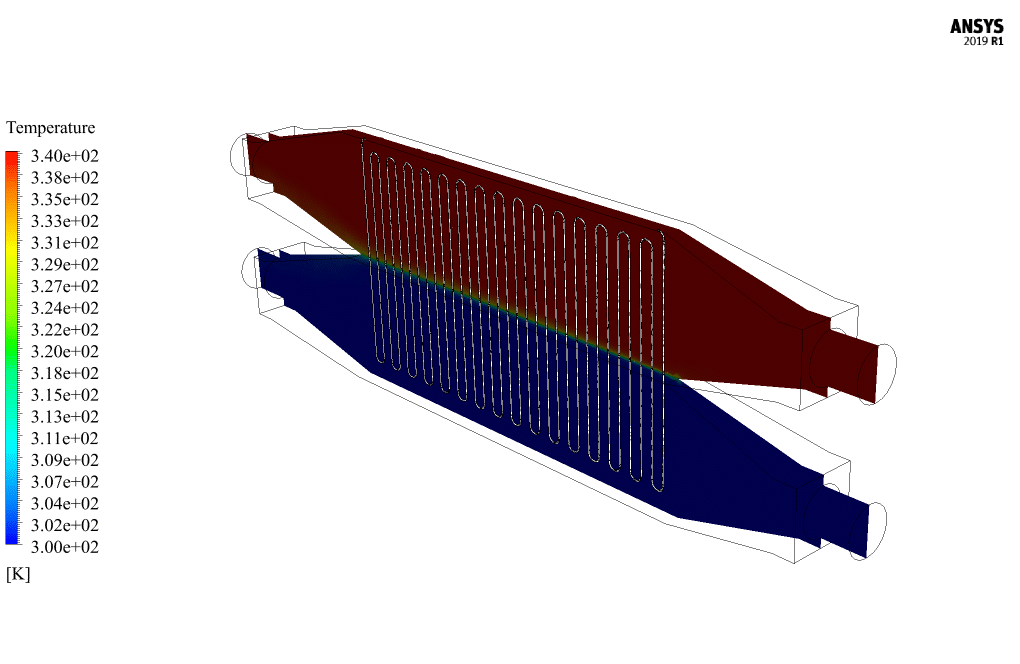
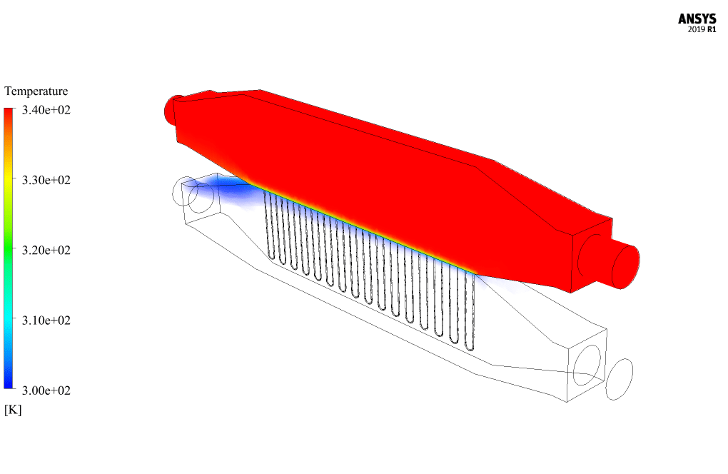
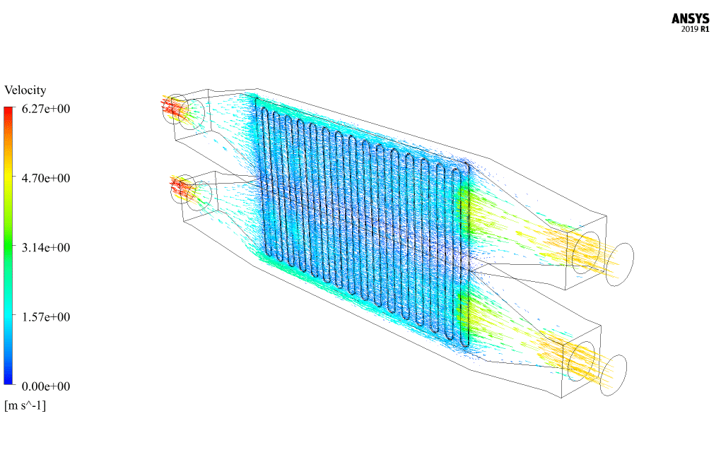
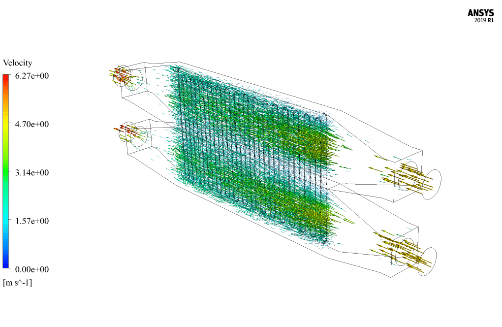
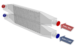
The present problem simulates heat transfer within a heat exchanger in three dimensions using ANSYS Fluent software. In this simulation, the HEX consists of two parts; the upper part is for the passage of the hot current, and the lower part is for the passage of the cold current. Also, a twisted barrier is used inside the HEX to affect the flow rate of hot and cold water and, consequently, increase the heat transfer between them. Hot water flow with a speed of 5 ms-1 and temperature of 340 K enters from the upper part of the HEX, and cold water flow enters with a speed of 5 ms-1 and temperature of 300 K from the lower part. This work investigates the heat transfer process between the cold and hot sides of the HEX.
Heat Exchanger Geometry & Mesh
The present model is designed in three dimensions using Design Modeler software. The present model is related to a heat exchanger, consisting of two parts (the hot part at the top and the cold part at the bottom), and a twisted barrier is used inside it.
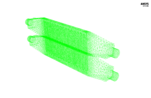
We carry out the model’s meshing using ANSYS Meshing software. The mesh type is unstructured. The element number is 1201056. The following figure shows the mesh.
Heat Exchanger CFD Simulation
We consider several assumptions to simulate the present model:
- We perform a pressure-based solver.
- The simulation is steady.
- The gravity effect on the fluid is ignored.
The following table represents a summary of the defining steps of the problem and its solution:
| Models (Heat Exchanger) |
||
| Viscous | k-epsilon | |
| k-epsilon model | standard | |
| near wall treatment | standard wall functions | |
| Energy | On | |
| Boundary conditions (Heat Exchanger) |
||
| Hot Inlet | Velocity Inlet | |
| velocity magnitude | 5 m.s-1 | |
| temperature | 340 K | |
| Cold Inlet | Velocity Inlet | |
| velocity magnitude | 5 m.s-1 | |
| temperature | 300 K | |
| Hot Outlet | Pressure Outlet | |
| gauge pressure | 0 pascal | |
| Cold Outlet | Pressure Outlet | |
| gauge pressure | 0 pascal | |
| Middle Wall | Wall | |
| wall motion | stationary wall | |
| thermal condition | coupled | |
| Other Walls | Wall | |
| wall motion | stationary wall | |
| heat flux | 0 W.m-2 | |
| Methods (Heat Exchanger) |
||
| Pressure-Velocity Coupling | SIMPLE | |
| Pressure | second order | |
| momentum | second order upwind | |
| turbulent kinetic energy | first order upwind | |
| turbulent dissipation rate | first order upwind | |
| energy | second order upwind | |
| Initialization (Heat Exchanger) |
||
| Initialization methods | Standard | |
| gauge pressure | 0 Pascal | |
| x-velocity | 5 m.s-1 | |
| y-velocity & z-velocity | 0 m.s-1 | |
| temperature | 340 K (patch) | |
Heat Exchanger with Twisted Barrier Results & Discussions
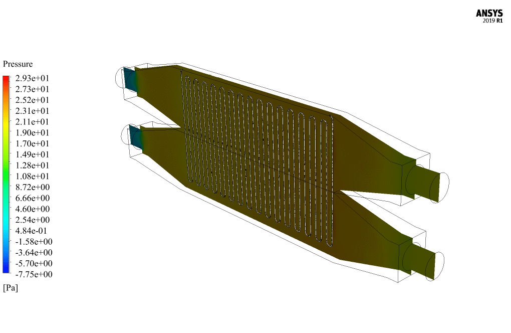
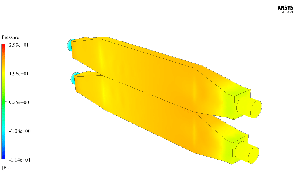
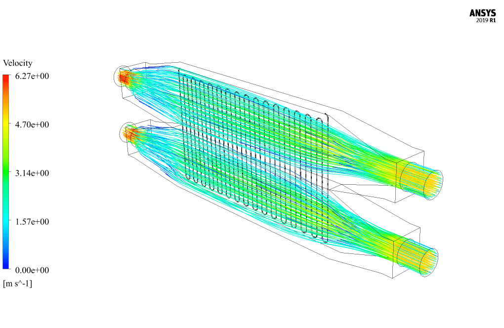
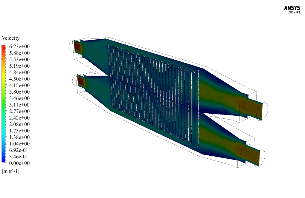
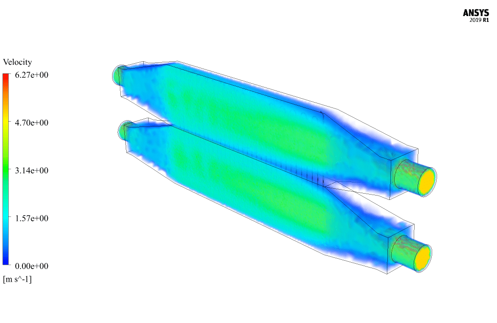
At the end of the solution process, two-dimensional and three-dimensional counters related to pressure, velocity, and temperature inside the heat exchanger are obtained. Two-dimensional and three-dimensional path lines and two-dimensional and three-dimensional velocity vectors are also obtained. The results show that heat transfer has occurred between the cold and hot sides of the heat exchanger.


Dr. Cassandra McLaughlin –
The detailed description of the heat exchanger simulation is truly insightful. I am particularly impressed with the use of a twisted barrier to enhance heat transfer efficiency. Great work!
MR CFD Support –
We are so glad to hear that you’re impressed with the simulation of the Heat Exchanger with Twisted Barrier. Our team strives to help ensure a deeper understanding and practical knowledge of CFD simulations. Thank you for acknowledging our efforts!
Missouri Schimmel –
I’m impressed with how this training demonstrates heat transfer within a complex geometry! Do the twisted barriers significantly increase overall heat transfer efficiency compared to straight barriers?
MR CFD Support –
Thank you for the positive feedback! Yes, the twisted barrier design significantly enhances the turbulence of the flow within the heat exchanger, which in turn increases the heat transfer rate and efficiency as compared to a heat exchanger with straight barriers.
Mrs. Maria Schmeler –
I’m impressed by the level of detail in the simulation method for the Heat Exchanger training. The twisted barrier seems to be a unique feature. How effective is it in enhancing the heat transfer as compared to traditional straight baffle designs in HEXs?
MR CFD Support –
The twisted-barrier design in this heat exchanger plays a significant role in enhancing heat transfer. It promotes turbulence and increases the overall heat exchange area, which improves the thermal efficiency compared to straight-baffle designs that offer less disturbance to the flow pattern. The increased heat transfer rate is crucial for the efficiency of the system.
Austen O’Conner –
The training was exceptional! The clarity in simulation setup and the step-by-step guidance in ANSYS Fluent were incredibly helpful. The twisted barrier’s impact on heat transfer was fascinating to see visualized. Great learning tool for understanding complex heat exchanger operations!
MR CFD Support –
We’re thrilled to hear that you found our Heat Exchanger with Twisted Barrier CFD Simulation training to be helpful and that the visuals made the complex concepts easier to understand. Thank you for your positive feedback, and we’re glad to have facilitated your learning journey!
Miss Daisha Gutmann V –
The simulation outcome for the effectiveness of the twisted barrier is clearly visible in enhancing heat transfer. Well done on such a detailed analysis!
MR CFD Support –
Thank you very much for your positive feedback! We’re pleased that the detailed analysis met your expectations and that you could clearly see the effectiveness of the twisted barrier in the simulation. If you have any further questions or need assistance with another simulation, please do not hesitate to reach out.
Shad Kirlin II –
I’m genuinely impressed with the detailed analysis of the heat transfer process in this CFD simulation, especially the influence of the twisted barrier. The results must offer valuable insights!
MR CFD Support –
Thank you for your kind words! We are thrilled to hear that you found the heat exchanger simulation analysis with the twisted barrier insightful. It’s great to know that our efforts are appreciated. We continuously strive to provide detailed and valuable analyses in our learning products. If you have any more feedback or need further assistance, please let us know!
Dr. Robert Considine –
I’m truly impressed by the in-depth analysis and simulation work done on the heat exchanger with a twisted barrier. The clear and detailed explanations on the control of flow and heat transfer enhancement using the barrier show the complexity and precision of the work. It’s amazing to see such intricate simulations of temperature differentials and fluid motion that can be achieved using ANSYS Fluent. These results must be critical for optimizing heat exchanger designs.
MR CFD Support –
Thank you for your kind words and appreciation! We’re delighted to know that our detailed simulation of the heat exchanger with the twisted barrier in ANSYS Fluent provided valuable insights and met your expectations. Your feedback encourages us to continue delivering high-quality CFD simulations and analyses. Should you be interested in further functionalities or specific aspects of our simulations, please don’t hesitate to reach out!
Lon Littel –
Absolute joy to learn about the twisted barrier design in heat exchangers. It’s fascinating to see how the design affects heat transfer efficiency. My own project was inspired by your clear presentation of the concept!
MR CFD Support –
Thank you for your positive feedback. We are delighted to hear that our CFD training helped inspire your project and you appreciated the clear presentation of the twisted barrier’s impact on heat transfer. It’s great to know our materials are being put to good use!
Waino Ryan –
I’m elated to see how effective the twisted barrier is in increasing heat exchange! Is there any data on the increased efficiency for this model?
MR CFD Support –
Thank you for your kind words about the heat exchanger simulation! We’re thrilled that you’re impressed with the twisted barrier’s impact on heat transfer. The detailed results of the simulation, including the efficiency increase, are typically provided in the comprehensive final report. This data would show the temperature distribution and heat transfer enhancements thanks to the inclusion of the twisted barrier. If you have specific queries regarding the quantitative efficiency improvements, please let us know, and we would be more than happy to provide additional information.
Adalberto Bartell –
This training product exceeded my expectations! The twisted barrier concept is a great example of enhancing heat exchange efficiency. Incredible how detailed the simulations are and the learning curve was made absolutely manageable with the clear explanations. Is the included mesh sufficiently refined near the twisted barrier where heat transfer is critical?
MR CFD Support –
Thank you for your positive feedback! It delights us to know our training product facilitated your understanding. Yes, the mesh is deliberately refined around the twisted barrier to capture the heat transfer phenomena effectively. Ensuring accurate simulation of temperature gradients and fluid flow interactions in that region.
Miguel Hoeger –
I just completed my CFD project on which I configured a heat exchanger in ANSYS based on MR CFD’s Heat Exchanger with Twisted Barrier simulation training. I must say, the detailed step-by-step instructions and robust explanation on velocity, pressure settings, and temperature distribution made the learning curve much smoother. I could genuinely grasp not only the setup but adapt my knowledge to optimise my project. Truly invaluable resource for anyone dealing with thermal systems in engineering!
MR CFD Support –
Thank you for your positive feedback! We’re thrilled to hear that our Heat Exchanger with Twisted Barrier CFD Simulation training has been so helpful for your project. It’s great to know that our detailed instructions and clear explanations have made a significant impact on your learning experience and project success. If you ever have any questions or need further assistance in your CFD journey, please don’t hesitate to reach out. Keep up the excellent work!
Xzavier Jaskolski –
The twisted barrier’s enhancements in heat transfer create an interesting study for sure. Impressed by your comprehensive approach and detailed model setup!
MR CFD Support –
Thank you so much for your kind words! We’re thrilled to hear that you found the simulation details and approach comprehensive. It’s always our goal to deliver a clear and thorough understanding of each concept and we’re glad you’re impressed with how the twisted barrier enhances the heat transfer within the HEX simulation. If there’s any aspect of our products or simulations you’d like to know more about, please feel free to ask.