
Pipe with Twisted Tape Inserts Heat Transfer, Validation
Free
- The problem numerically simulates Heat Transfer in Pipe with Twisted Tape Inserts using ANSYS Fluent software.
- We design the 3-D model with the Design Modeler software.
- We Mesh the model with ANSYS Meshing software, and the element number equals 476442.
- This project is simulated and validated with a reference article.
To Order Your Project or benefit from a CFD consultation, contact our experts via email (info@mr-cfd.com), online support tab, or WhatsApp at +44 7443 197273.
There are some Free Products to check our service quality.
If you want the training video in another language instead of English, ask it via info@mr-cfd.com after you buy the product.
Description
Heat Transfer in Pipe with Twisted Tape Inserts, Paper CFD Validation, ANSYS Fluent CFD Simulation
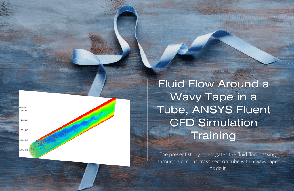
The problem simulates heat transfer within a tube with a twisted strip using ANSYS Fluent software. The simulation process is based on the data in the reference article “Analysis of Heat Transfer in Pipe with Twisted Tape Inserts.” The results are compared with the results in the paper and validated.
The model is related to a tube inside which a twisted tape with a certain screw pitch is placed. The present model is designed in three dimensions using Design Modeler software.
The model consists of a tube with a diameter of 0.022 m and a length of 2.2 m, which in its interior has a twisted tape with a screw pitch equal to 0.110 m. Therefore, the ratio of the tape screw pitch to the pipe diameter is equal to 5.
The meshing has been done using ANSYS Meshing software, and the mesh type is unstructured. The element number is 476442.
Methodology
The fluid flowing inside this pipe is water with Reynolds equal to 800; as a result, the flow velocity of the incoming water is equal to 0.0365 m/s. Also, the inlet water flow temperature to the pipe is equal to 298.15 K, and the pipe wall is under a constant heat flux equal to 5725 W/m2.
The strip inside the pipe is thermally insulated and is solely responsible for affecting the amount of heat transfer from the wall of the pipe to the mass of fluid flowing inside the pipe.
Conclusion
This work aims to investigate the amount of Nusselt number on the pipe wall. So, at the end of the solution process, the value of the Nusselt number is obtained on the pipe wall.
This value was obtained when the Reynolds value of the flow is equal to 800, and the ratio of the pitch of the twisted strip to the diameter of the pipe is equal to 5.
Calculating the Nusselt value requires the correct reference values; So that in the present model, the characteristic length is equal to the diameter of the pipe, i.e., 0.022 m, and the reference temperature is equal to the bulk temperature of the fluid inside the pipe, which is equivalent to 306.7147 K.
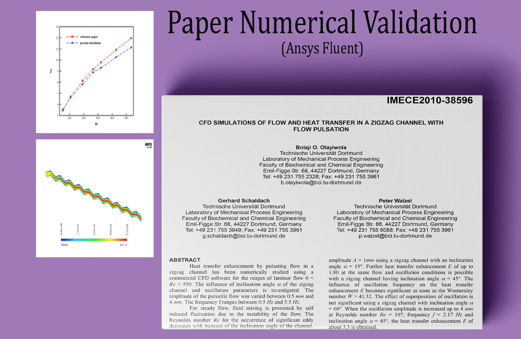
The comparisons of the results of the present CFD simulation with the results of the article and the validation of the results have been done using the diagram of Figure 2 of the reference paper.
| P/D | Re | Nusselt number @ paper | Nusselt number @ present Simulation |
| 5 | 800 | 24.78 | 25.737018 |
Also at the end, three-dimensional contours related to pressure, temperature, and velocity as well as three-dimensional path lines are obtained.
Reviews
You must be logged in to post a review.

Ladarius Moen –
The work done on simulating heat transfer in a pipe with twisted tape inserts is commendable. Being able to see how closely the CFD simulation matches the validation paper’s results provides great confidence in the methodology used. Absolutely impressive!
MR CFD Support –
Thank you for your kind words! We are thrilled to hear that our product met with your expectations and provided you with the confident insights you needed. Our team works diligently to ensure accuracy and reliability in our simulations, so it’s always rewarding to receive such positive feedback. Thank you for choosing our service!
Herminia Emmerich –
The specific details on the validation process are impressive. It’s essential for practical application of the results. Great job on these thorough simulations!
MR CFD Support –
Thank you for your kind words! We take pride in ensuring our simulations are both accurate and reliable through rigorous validation processes. Your appreciation motivates us to continue delivering high-quality CFD simulation work.
Bettye Roob –
This tutorial offers a clear understanding of heat transfer enhancement using twisted tape inserts. Could you please provide further insights about the effects of the tape’s twist ratio on heat transfer efficiency?
MR CFD Support –
The use of the twisted tape and its particular twist ratio significantly influences the turbulent regimen inside the pipe, which enhances the heat transfer rate. The twist ratio determines the level of turbulence and can affect the boundary layer thickness, which in turn impacts the overall heat transfer coefficient. A lower twist ratio typically results in more turbulence, thereby enhancing heat transfer.
Rodrick Brakus PhD –
This simulation sounds quite comprehensive. Could simulations with twisted tape inserts be further optimized to improve heat transfer rates?
MR CFD Support –
In CFD simulations of heat transfer, optimizing configurations like twisted tape inserts can indeed enhance thermal performance. Factors such as the tape’s twist ratio, material properties, and the flow dynamics can be systematically varied to investigate possible improvements in heat transfer rates.
Evangeline Kuhlman –
What are the key factors that lead to enhanced heat transfer with the twisted tape insert in the pipe?
MR CFD Support –
The twisted tape inserts in the pipe serve to increase turbulence within the fluid flow, which enhances the mixing of water molecules. The increased turbulence ensures better thermal contact between the fluid and the pipe walls. The twist in the tape creates a swirl flow that disrupts the thermal boundary layer, resulting in an increased Nusselt number and improved heat transfer efficiency.
Mrs. Josefina Doyle –
I had a fantastic time working through the Pipe with Twisted Tape Inserts Heat Transfer tutorial. The step-by-step process mirrored the paper’s validation very closely, and I was impressed with how thoroughly the methodology was explained. Not only did I learn a lot, but seeing the simulation results closely match the categorized paper gave me confidence in using CFD studies for my own projects!
MR CFD Support –
Thank you so much for your kind words! We are thrilled to hear that our tutorial met your expectations and helped build your confidence in conducting CFD simulations. It’s great to know that our efforts in ensuring the accuracy and instructional quality are having a positive impact. We appreciate you taking the time to share your experience and hope to continue providing you with valuable learning resources!