Horizontal Axis Wind Turbine (HAWT) Aerodynamic, ANSYS Fluent Training
$140.00 Student Discount
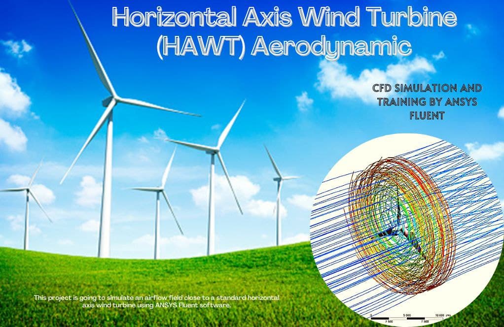
- The problem numerically simulates horizontal axis wind turbine (HAWT) aerodynamics using ANSYS Fluent software.
- We design the 3-D model by the Design Modeler software.
- We Mesh the model by ANSYS Meshing software, and the element number equals 2463521.
- We use the Frame Motion to define rotational movement around the turbine.
To Order Your Project or benefit from a CFD consultation, contact our experts via email ([email protected]), online support tab, or WhatsApp at +44 7443 197273.
There are some Free Products to check our service quality.
If you want the training video in another language instead of English, ask it via [email protected] after you buy the product.
Description
Description
This simulation is about horizontal axis wind turbine (HAWT) aerodynamics via ANSYS Fluent software. We perform this CFD project and investigate it by CFD analysis.
Standard Horizontal Axis Wind Turbine (HAWT) is becoming increasingly critical in wind power generation. Fortunately, it is known that HAWTs have higher efficiency compared to VAWTs. Thus, they have been employed in open fields and can produce energy from the wind.
As wind tunnel experiments are expensive in terms of both costs and time, another way to study the aerodynamic behavior of the wind turbine is to use CFD. In this project, CFD has been employed to evaluate this type of turbine in this study.
The geometry included a rotary zone for the turbine walls and a stationary zone for the rest of the domain. The inlet is considered to wind at 1 m/s, and the turbine zone rotates at 16 RPM.
An incompressible and isothermal condition is a valid assumption for the current simulation. This study aims to investigate the behavior of airflow and pressure distribution and study drag force.
The geometry of the present model is drawn by Design Modeler software. The model is then meshed by ANSYS Meshing software. The model mesh is unstructured, and 2463521 cells have been created.
Horizontal Axis Wind Turbine Method
In this simulation, the MRF (Frame Motion) option has been activated to model the rotation of the turbine. In fact, it is assumed that the fluid around the turbine blades is rotating instead of the turbine blades themselves.
The rotational velocity of this fluid is equal to the rotational velocity of the turbine. In order to do this, the MRF tool is used in Cell Zone Conditions.
Horizontal Axis Wind Turbine Conclusion
After simulation, the contours of pressure, velocity, and surface pressure are obtained. Also, the streamlines of fluid around the turbine are obtained. The streamlines illustrate the flow quality resolved in the wake section, which is the core challenge of aerodynamic simulation.
The contours show that the leading edge of the turbine wall corresponded to the lowest pressure, which is entirely logical since the velocity has the highest value on the tip of the turbine blade. Also, the velocity field adjacent to the wall of the turbine has the highest gradient.
Finally, we calculate the drag force equal to 243.63 (N), which is accurate for a 3-meter turbine with the noted specifications.


Julie Padberg –
I found the content about HAWT aerodynamics simulation very insightful! The intricacies of modeling airflow and the way MRF has been employed were intriguing. It’s fascinating to see the complexities of wind turbines brought to light through simulation. Great job!
MR CFD Support –
Thank you for your positive feedback! We are thrilled that our training on HAWT aerodynamics using simulation met your expectations and provided insightful information on the physics and engineering behind wind turbines. It’s wonderful to hear that the MRF method caught your interest and you found the materials well-presented. Your support is highly appreciated!
Dr. Dustin Windler –
I completed the ANSYS Fluent training for the Horizontal Axis Wind Turbine (HAWT), and I’m impressed by how clearly the simulation presented the relation between pressure distribution and the aerodynamic performance of the turbine. It provided an in-depth understanding of factors that influence the efficiency of wind turbines.
MR CFD Support –
Thank you for your positive feedback! We’re delighted to know that our CFD project on the aerodynamics of the Horizontal Axis Wind Turbine (HAWT) using ANSYS Fluent was informative and successful in providing you with a clear understanding of wind turbine efficiency. Your comprehension of the material encourages us to keep offering high-quality learning experiences.
Miss Clotilde Kerluke –
I’m absolutely impressed with the detailed aerodynamic simulation of the HAWT. The approach to use CFD for understanding complex wind behavior on turbine blades, instead of costly wind tunnel experiments, is incredibly efficient and innovative. The MRF application for blade rotation simulation and the resultant detailed drag force calculations are particularly noteworthy features that underscore the comprehensive nature of this study. Well done on a remarkable CFD project.
MR CFD Support –
Thank you for your positive feedback! We are thrilled to hear that you found the HAWT aerodynamic simulation helpful and that the use of the MRF tool and CFD analysis met your expectations. It’s always our goal to provide efficient and innovative ways to study complex phenomena like turbine aerodynamics. We appreciate your recognition of the effort and detail put into this project.
Shanny Hammes II –
I was fascinated by how the MRF method was used in the simulation of the turbine rotation. How does this compare in terms of accuracy and computational cost with a moving mesh simulation that would rotate the actual turbine geometry?
MR CFD Support –
The MRF (Multiple Reference Frame) method is quite efficient in simulating rotating machinery such as wind turbines, particularly because it does not require the mesh to deform or move. This static mesh approach simplifies the computations and results in lower computational costs and faster simulations compared to a moving mesh which requires complex motion algorithms and greater computational resources. In terms of accuracy, the MRF can deliver credible results for steady or quasi-steady cases. However, moving mesh or sliding mesh techniques might provide higher fidelity results for transient, highly dynamic interactions but at increased computational expense.
Dr. Keely Bogisich V –
The MRF method is a clever choice, but I’m curious, might it impact the accuracy of resolving flow patterns, especially near the blade tips?
MR CFD Support –
The MRF method is a common approximation used in CFD to model rotating machinery efficiently. While it simplifies the simulation by assuming a steady state rotational effect around the blades, it may not perfectly capture the complex transient flow patterns like dynamic stall at the blade tips. For highly accurate tip resolution, a transient simulation with actual blade rotation might be necessary.
Ocie Marvin –
I’m really impressed with the detailed analysis of the HAWT aerodynamics. The use of CFD in assessing wind turbine performance is clearly articulated in the training product. Great job displaying the potential of simulation as a cost-effective alternative to wind tunnel testing.
MR CFD Support –
Thank you so much for your positive feedback! We’re thrilled to hear that you found our CFD analysis and simulation of the HAWT both informative and instrumental in demonstrating the efficiencies that computer-aided design can bring to the field of wind energy. Stay tuned for more insightful learning products from MR CFD!
Rebecca Schowalter Jr. –
This project on the HAWT using ANSYS Fluent was truly informative. The detailed explanation of how the rotational motion was modeled with the MRF tool instead of physically rotating the turbine blades was particularly enlightening. The clear presentation of results with pressure and velocity contours, as well as drag force calculations, has enhanced my understanding of wind turbine aerodynamics. Well done to the MR CFD team on producing such a comprehensive and applicable simulation.
MR CFD Support –
We are really glad to hear that you found the HAWT CFD project informative and helpful. Understanding the aerodynamics of wind turbines is crucial for optimizing their performance and our team strives to provide clear, detailed simulations to aid learning. Thank you for taking the time to review our work!
Marcos Heathcote –
I’m really fascinated by the level of detail in this simulation. Great explanation on how the MRF tool is applied for the turbine rotation!
MR CFD Support –
We’re thrilled to hear that you appreciate the thorough details of our HAWT aerodynamics simulation using ANSYS Fluent. Our team always strives to provide comprehensive insights into the CFD process. Thank you for your positive feedback, and if you need further information on our simulations or any other assistance, please feel free to reach out.
Ms. Rachelle Hudson –
I’m amazed at the detail included in the airflow and drag force analysis! It’s very clear and helps me understand the dynamics better. Can you tell me more about how the MRF tool simulates the rotation and how accurate it is compared to the actual physical rotation of turbine blades?
MR CFD Support –
Thank you for your compliment! In the simulation, the MRF (Multiple Reference Frame) tool simplifies the rotation by considering the fluid domain around the turbine blades as rotating. This approach circumvents the computational challenge of mesh deformation related to actual physical rotation. The accuracy of the MRF model is reliable for steady-state conditions and offers a good approximation for the airflow and forces around the blades. However, it might not capture the transient details as vividly as transient simulations would. For that level of accuracy, a different CFD approach known as the Sliding Mesh Model (SMM) might be required.
Bertram Stamm –
I can’t believe how detailed the airflow patterns are displayed! Such a comprehensive analysis indeed aids in understanding the aerodynamics of HAWTs.
MR CFD Support –
Thank you for your feedback! We’re pleased to hear that our CFD analysis effectively illustrated the airflow patterns and provided a deep understanding of HAWT aerodynamics. If you have any more questions or need further assistance, feel free to ask.
Joey Mraz –
This training on HAWT aerodynamics sounds very detailed. Can you tell me how the power coefficient (Cp) is calculated within the simulation?
MR CFD Support –
The power coefficient (Cp) of a HAWT is not computed directly within ANSYS Fluent in this simulation. To evaluate the Cp value, you would calculate the mechanical power output from the torque and rotational speed data provided by the simulation and then use the wind speed and turbine geometry to calculate the available power in the wind. The ratio of the two powers gives you the Cp for the turbine. If you need assistance calculating this coefficient, we can provide guidance on setting up the derived expression inside Fluent or the necessary post-processing steps.
Wanda Spinka Jr. –
I find the results on drag force to be particularly insightful for practical applications. Great simulation work!
MR CFD Support –
Thank you for your kind words and recognition of the simulation’s practical value. We’re glad you found the insight on drag force useful. If you have any further questions or need more information, feel free to reach out to us!
Giovanni Lehner Jr. –
I was really impressed by the use of the MRF option to simulate the rotation of the turbine in this project. It’s clever that it can simplify the process by assuming the fluid around the turbine blades is rotating. Great use of the software’s features!
MR CFD Support –
Thank you for your positive feedback on our simulation of the Horizontal Axis Wind Turbine (HAWT) using ANSYS Fluent. We’re glad to hear you appreciate the effective application of the Moving Reference Frame (MRF) approach. Our aim is to continually deliver high-quality and insightful simulations. Your satisfaction is a fantastic encouragement for us to keep improving!
Lempi Hermann –
I’m impressed with how the Horizontal Axis Wind Turbine CFD was simulated. Kudos to the team for their hard work and detailed analysis. The results with the airflow streamlines, pressure distribution, and force calculations provide great insights for understanding turbine aerodynamics. Can’t wait to apply this learning to my own projects.
MR CFD Support –
We sincerely appreciate your kind words and are thrilled to hear that you found the HAWT CFD simulation insightful. It’s fantastic to know that you’ll be able to apply what you’ve learned to your projects. Thank you for choosing our training program, and we look forward to supporting you in your future endeavors.
Dr. Deontae Zulauf –
The way you explained the use of the MRF tool: was this clear enough for somebody starting out in CFD or do they need a more basic explanation about how the rotating frame influences the results?
MR CFD Support –
Thank you for your positive feedback! Our material aims to be as informative as possible for all learners. However, if more clarity is needed, especially for newcomers to CFD, our support team can provide a simplified explanation of the MRF concept and its impact on results. We encourage users to reach out with specific questions for personalized assistance.
Dr. Kiley Kohler –
The tutorial was incredibly comprehensive. For someone completely new to CFD, this was a user-friendly introduction to analyzing aerodynamic performance in wind turbines. Great job on providing detailed explanations on defining boundary conditions and interpreting the results, particularly the pressure distribution and how it relates to blade design.
MR CFD Support –
Thank you for the positive feedback on the Horizontal Axis Wind Turbine aerodynamics simulation tutorial! We’re delighted to hear that you found it user-friendly and informative for a newcomer to CFD. We strive to provide clear, comprehensive guidance for understanding crucial aspects of simulations, and we’re pleased you noticed the effort taken in explaining interactions such as pressure distribution. We hope our products continue to support and innovate your journey in computational fluid dynamics!
Linwood Carter –
The training materials for the HAWT Aerodynamics simulation were highly educational and provided me with a thorough understanding of applying CFD analysis using ANSYS Fluent. The well-drawn geometry and the complexities addressed within the simulation were quite impressive!
MR CFD Support –
Thank you for your positive feedback! We are thrilled to hear our HAWT Aerodynamics training has provided you with a solid understanding of CFD application in wind turbine simulations. Your mention of the complexities of the simulation and our efforts in geometry design is greatly appreciated!
Keegan Torphy –
Your CFD training package on HAWT aerodynamics provided me with excellent insights. The velocity and pressure distributions were particularly enlightening. Thank you for a great learning tool!
MR CFD Support –
Thank you for your positive feedback! We’re delighted to hear that the HAWT aerodynamics training package met your expectations and provided you with valuable insights into velocity and pressure distributions. We appreciate your support and are here to assist with any further learning needs in CFD.
Philip Bailey –
I really learned a lot about HAWT aerodynamics with your ANSYS Fluent training. The simulation results were intuitive and made it easier to understand the effects of different design parameters on performance.
MR CFD Support –
We’re delighted to hear that you found the training informative and helpful! It’s great that the simulation results added clarity to the aerodynamic components of wind turbines. If you have any further questions or need additional resources, we’re here to help. Thank you for your positive feedback!
Prof. Kristina Ankunding III –
I appreciated the way this simulation incorporated the MRF tool to replicate the turbine’s rotation while keeping the blades stationary for the simulation. Understanding the airflow and how it influences wind turbine efficiency has been a key area in my research. The detailed contours of pressure and velocity will certainly help visualize the real behavior of wind around the turbine blades.
MR CFD Support –
Thank you for sharing your positive experience with our Horizontal Axis Wind Turbine aerodynamic simulation using ANSYS Fluent. We’re glad to hear that our CFD project and the application of the MRF method have contributed valuable insights to your research. Your acknowledgment motivates us to continue delivering high-quality CFD simulations to our customers. If you need further assistance or have more questions, don’t hesitate to reach out!
Madge Marvin –
The ANSYS Fluent simulation for the HAWT is impressive! The level of detail provided in both velocity and pressure mapping really helps understand aerodynamic performance.
MR CFD Support –
Thank you for your positive feedback! We’re glad to hear you found the ANSYS Fluent simulation for the HAWT detailed and informative. If you have any more questions or need further insight into our simulations, feel free to reach out.
Lizeth Lueilwitz –
The detailed insights on the CFD simulation of a HAWT are fascinating. The results rendered provide a comprehensive understanding of how drag influences turbine performance.
MR CFD Support –
Thank you for your positive feedback on our CFD simulation tutorial for horizontal axis wind turbines. We’re glad to hear that you found the presentation and results beneficial for understanding turbine aerodynamics.
Dr. Henderson Anderson Jr. –
The HAWT training was superb; going through the CFD analysis really helped me grasp the aerodynamics involved. It’s fascinating to see how the leading edge of the turbine corresponds with the area of lowest pressure.
MR CFD Support –
Thank you for your positive feedback! We’re glad to hear that our HAWT aerodynamics training with ANSYS Fluent was able to enhance your understanding of wind turbine aerodynamics. If you have any more questions or need further assistance, feel free to reach out. Happy learning!
Prof. Jillian McClure Sr. –
I thoroughly enjoyed learning from the HAWT aerodynamics simulation! The step-by-step approach taught me so much about wind turbine efficiency and the use of CFD in place of wind tunnel experiments. The detail on airflow behavior around the blades and pressure distribution was especially impressive.
MR CFD Support –
Thank you for your positive feedback! We’re thrilled to hear that our HAWT aerodynamics simulation provided you with a comprehensive learning experience and valuable insights into turbine efficiency and CFD analysis. We’re proud to offer material that enhances understanding in such a crucial field of renewable energy. If you have any more questions or need further assistance, feel free to reach out.