Humidification Dehumidification (HDH) CFD Simulation, ANSYS Fluent Tutorial
$400.00 Student Discount
- The current CFD project simulates the humidification dehumidification (HDH) system which is a model of water desalination methods via ANSYS Fluent software.
- We have designed the geometry using ANSYS Design modeler software and created the mesh on this geometry using ANSYS meshing software.
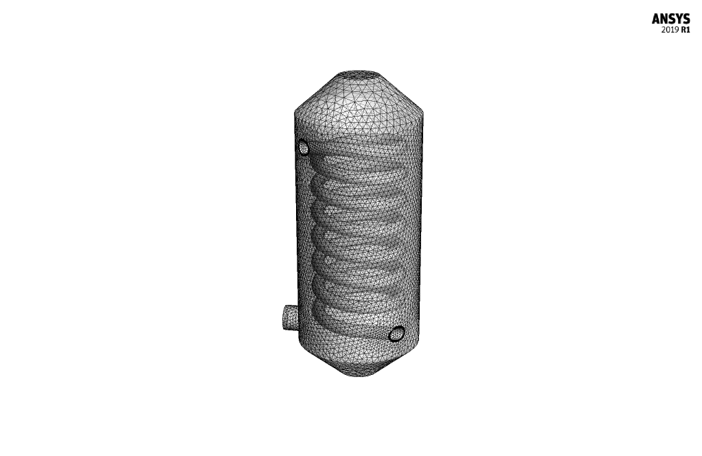
- The mesh type in the first simulation is Hybrid with 206,928 cells and Unstructured with 553,086 cells in the second case.
- The Discrete Phase Model (DPM), Species Transport Model, VOF Multiphase Model, Mass Transfer(Evaporation-Condensation), and a Porous Medium are used to analyze the project.
- Both Humidification and Dehumidification are simulated separately.
To Order Your Project or benefit from a CFD consultation, contact our experts via email ([email protected]), online support tab, or WhatsApp at +44 7443 197273.
There are some Free Products to check our service quality.
If you want the training video in another language instead of English, ask it via [email protected] after you buy the product.
Description
Description
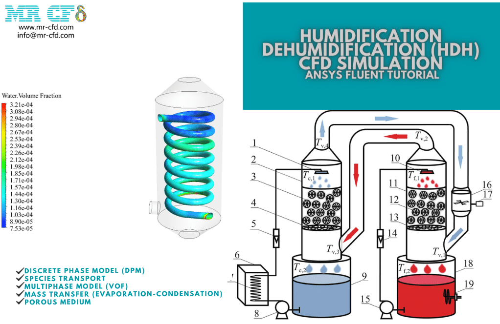
This CFD Project is about humidification dehumidification (HDH) system via ANSYS Fluent software. HDH system is a model of water desalination methods. The mechanism of this method is based on humidification and dehumidification processes. One side of the system is the evaporator or humidifier, and the other is the condenser or dehumidifier.
The cold water enters the spiral tubes inside the dehumidifier (condenser). Then it takes the heat of the steam inside the shell. Heat reception continues until the steam condenses, and as a result, the water inside the tube is heated. This hot water enters the humidifier (evaporator), and the hot water is sprayed on the filter plates of the evaporator.
These droplets are mixed with the dry air out of the condenser and form wet steam or humidified air. The resulting steam is pure, and its impurity settles in the evaporator. This pure steam is reheated by a heater and enters the condenser.
Now, the inside of the condenser shell is in contact with the cold feed water pipes (as mentioned before). It undergoes humidification or distillation of pure water from the steam. The mechanism of this system consists of two steps (humidification and dehumidification). So, two simulations have been done for this problem. The first simulation investigated humidification.
Dry air flows from the bottom of the chamber to the top. At the same time, droplets of hot salt water are sprayed through several holes inside the chamber. The droplets in the membrane part of the chamber collide with the airflow and, after evaporation, produce humid air.
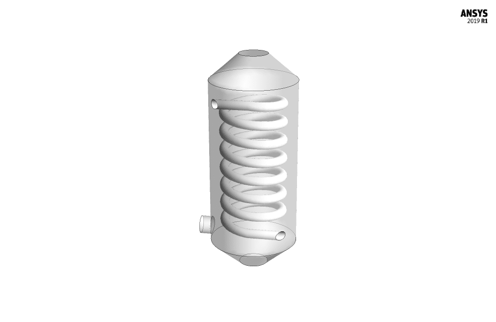
This steam is pure and free of salt. The second simulation investigated dehumidification. The flow of moist air created from the previous step enters the chamber. Inside the chamber, spiral tubes are considered to carry the cooling water flow. The contact of hot steam with the spiral tube’s cold surface causes condensation and freshwater production.
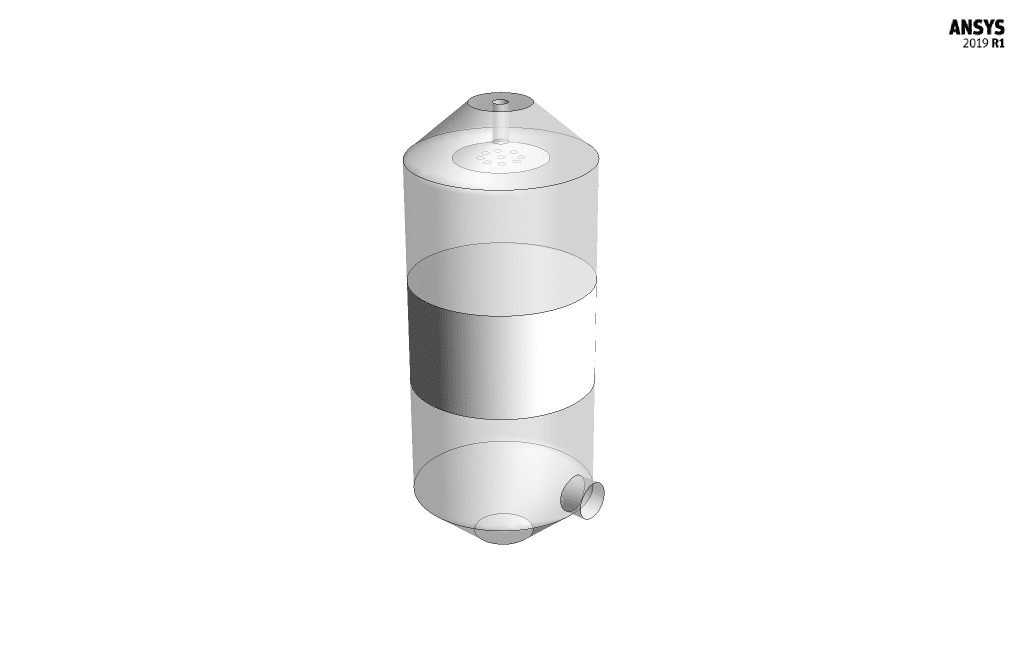
For simplicity, the pipe modeling is omitted, and the pipe wall is defined with a thermal boundary condition of constant temperature (cooling temperature). The geometry of the present project is modeled in three dimensions with Design Modeler software.
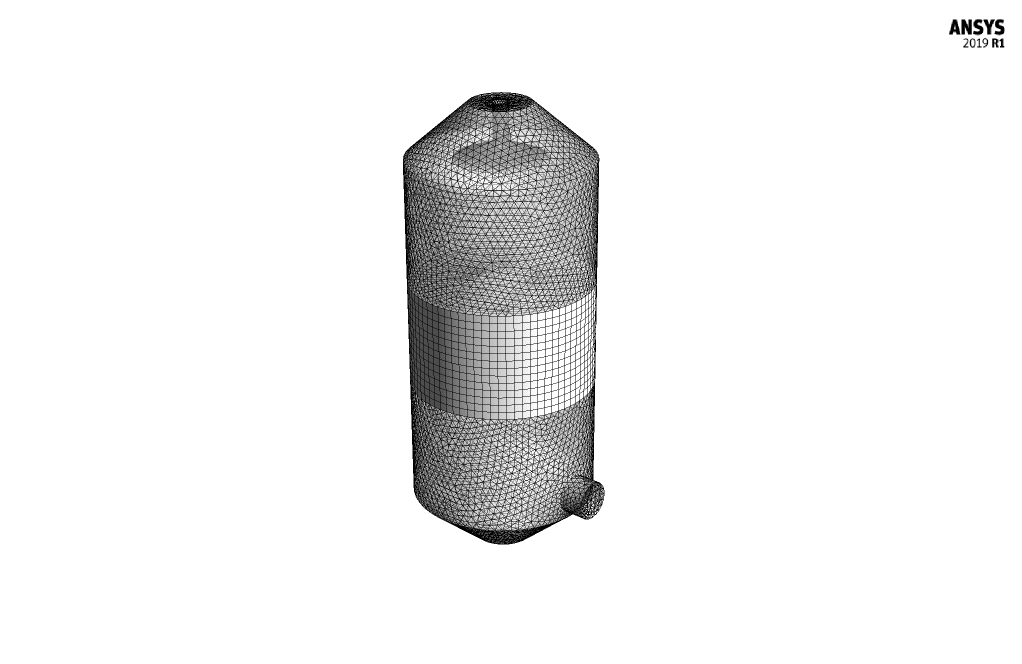
Then the model meshed with ANSYS Meshing software. The mesh of the first model is hybrid (a combination of structured and unstructured). The number of production cells is equal to 206,928. The mesh of the second model is unstructured, and 553,086 cells are created.
Methodology: Humidification Dehumidification (HDH)
In the first simulation, the salt water is sprayed from the chamber’s top. So it is necessary to define the discrete phase. Two approaches can be used to solve fluid equations and investigate fluid behavior. In the Eulerian approach, the fluid is assumed to be a continuous medium, and elements inside the fluid should be considered for solving equations.
In the Lagrangian approach, the fluid is considered as discrete particles, and the behavior of the fluid should be investigated particle by particle. In the humidification chamber, dry air enters the chamber as a continuous fluid and water spray droplets as a discrete phase.
So, in this simulation, the Discrete Phase Model has been used. The discrete phase is Unsteady and interacts with the continuous phase. After activating the discrete phase model, it is necessary to define the injection. The type of particle spraying is surface.
The particles are sprayed in the form of droplets, which turn into wet vapor as a result of evaporation. The diameter of the particles is equal to 1e-6 m, and it is released in 10 seconds. Since dry air enters the chamber and moist steam is produced inside the chamber, a Species Model should be used.
For this purpose, the Species Transport model has been used. This model deals with the solution of defined gas species transport equations. In addition, there is no need to define the chemical reaction between species.
Also, membranes are placed in the middle part of the humidity chamber to help the phase change process. A Porous Medium has been used to model these membranes. The porosity (equivalent to the ratio of void volume to total volume), viscous resistance (inverse of permeability), and inertial resistance must be determined in porous options.
In the second simulation, there is no need to define a discrete phase because no splashing occurs. Only the phase change from steam to water occurs in the dehumidifier chamber. The pure steam produced from the previous step turns into fresh water. Therefore, a Multiphase Model is used until two phases, including water liquid and water vapor, can be used simultaneously.
The multiphase model of VOF (Volume of Fluid) has been used in this problem. This model can completely separate two phases from each other and provide a distinct boundary between the two phases. Also, a Mass Transfer between water and steam must be defined for a phase change.
This phase change is defined in terms of Evaporation-Condensation. The evaporation-condensation mechanism is based on Lee’s Equations. For these equations, the saturation temperature and frequency of evaporation and condensation must be determined.
Conclusion
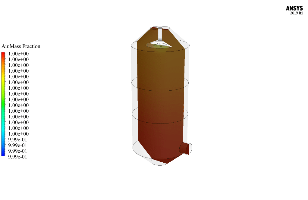
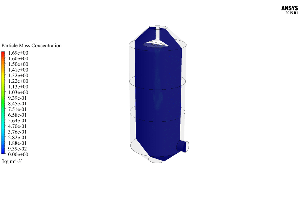
After the end of the first simulation, the contours related to the mass fraction of air and water vapor and the concentration of discrete particles have been obtained. Since this simulation is unsteady, the results are only related to the last second of the simulation.
Also, two animations have been prepared to understand this problem’s results better. One investigates the contour of changes in the mass fraction of produced h2O on a two-dimensional plane. The plane is passing through the chamber. The other investigates how water droplets spray over time using Particle Tracking.
The results show that, over time, the droplets are regularly sprayed downwards from the upper openings of the chamber to be ready to meet the dry air. Also, the results prove that with time, h2O is gradually produced and moves towards the upper exit of the chamber.
This shows that the simulation is done correctly because the goal of the problem was to produce humid air. In addition, the plot of the mass fraction of h2o produced over time has been obtained. This plot proves that as time goes by, more steam is produced.
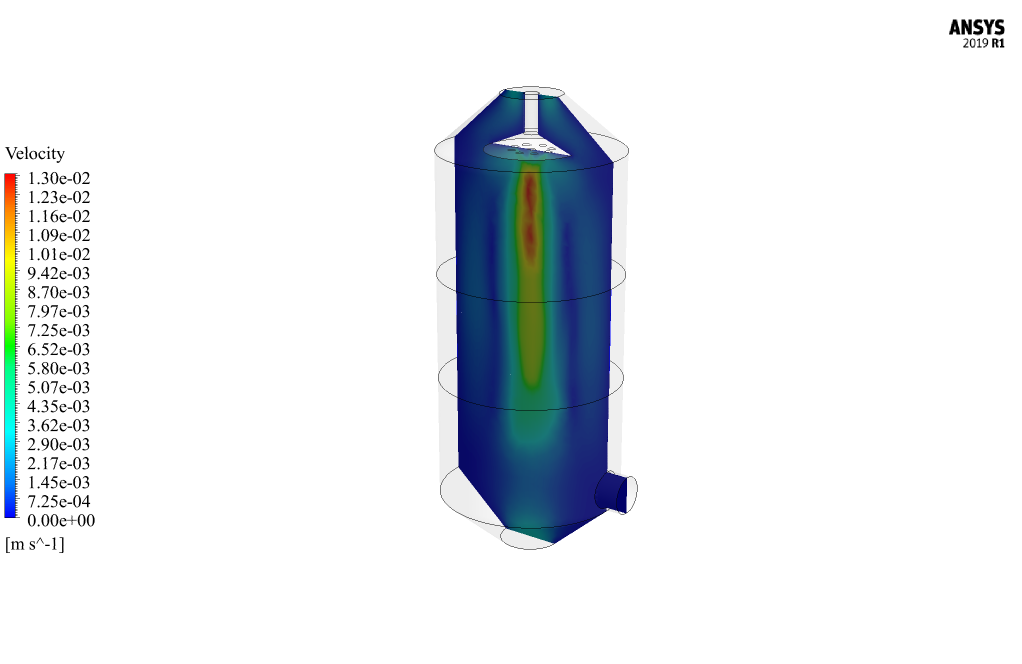
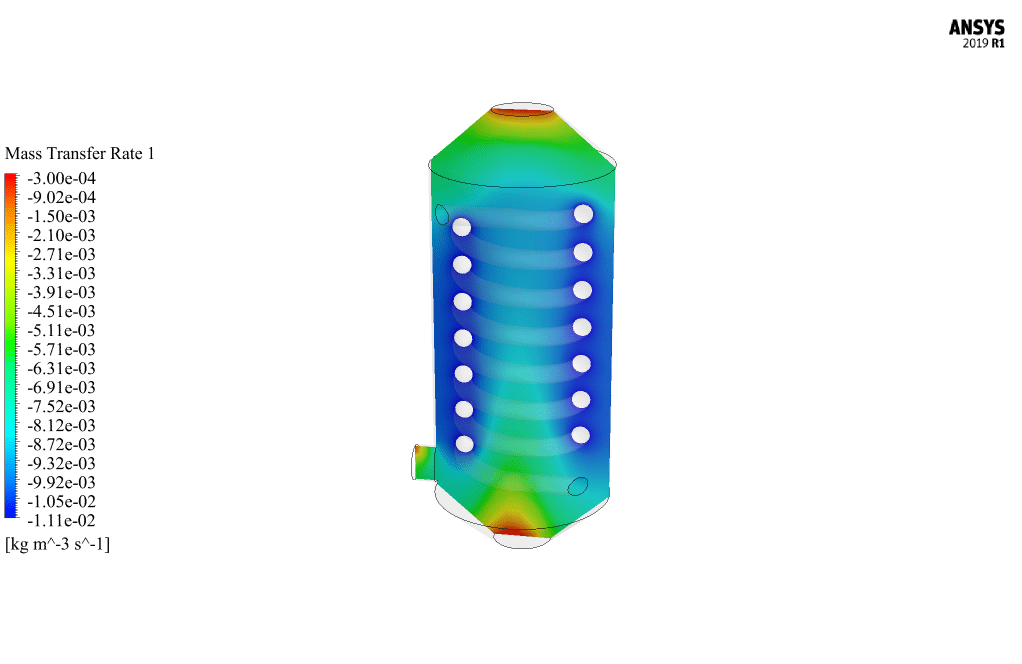
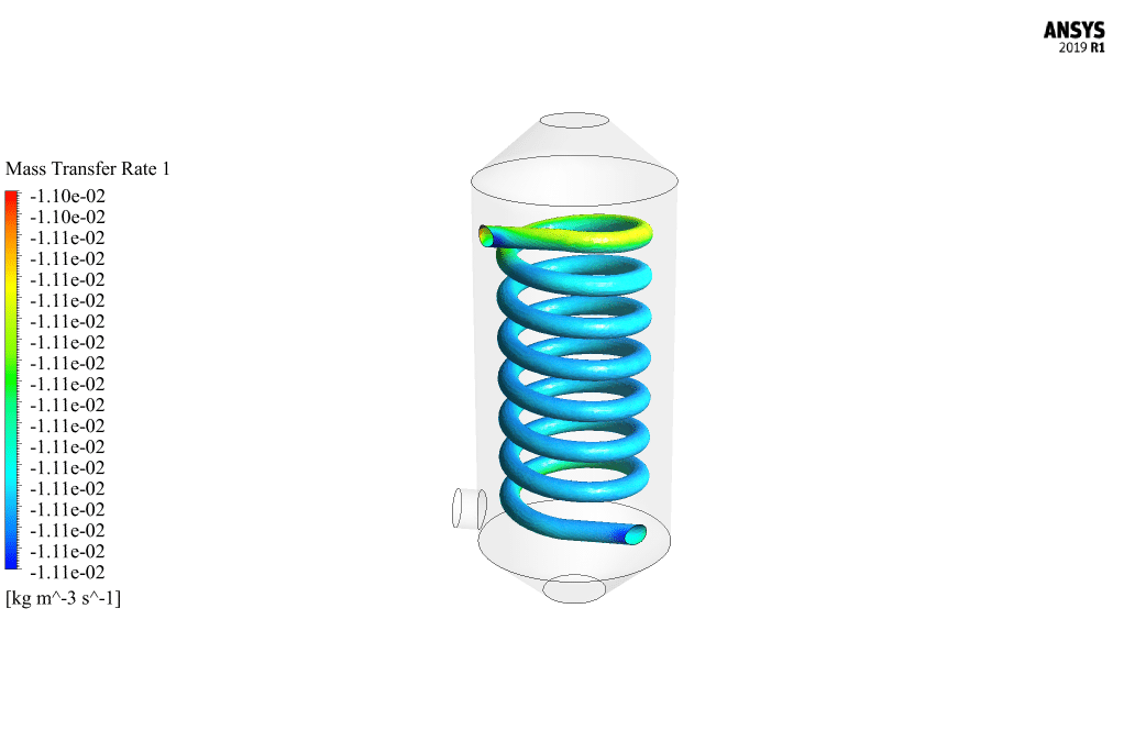
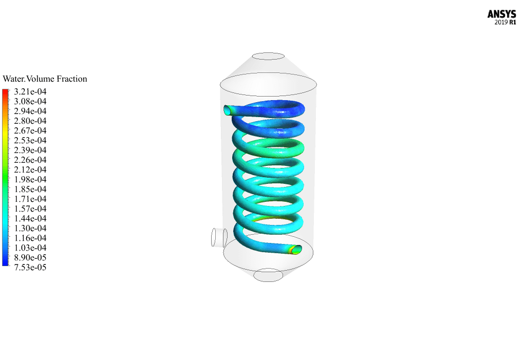
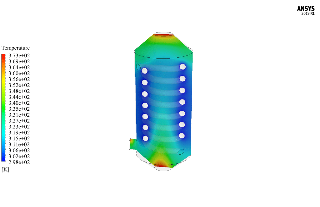
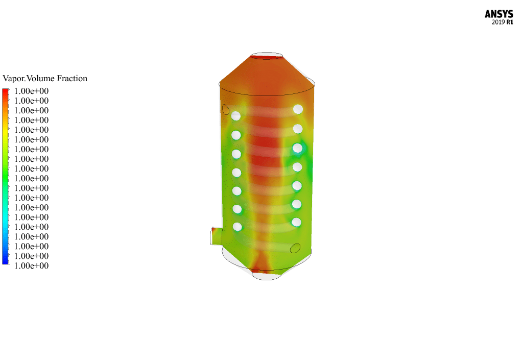
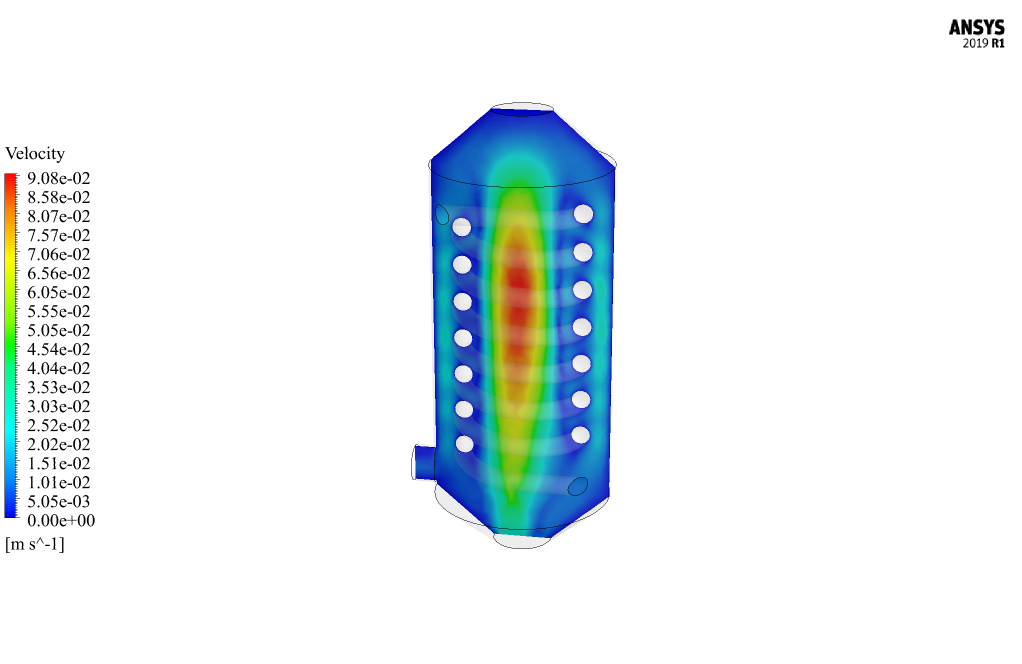
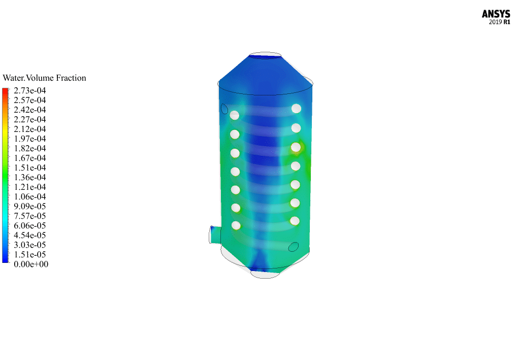
After the end of the second simulation, two-dimensional contours of velocity, temperature, mass transfer rate (from steam to water), and volume fraction of water and steam have been obtained. This simulation has been performed steadily and independently of time.
The results show the phase change in the regions around the cold spiral tube. The temperature contour shows that the vapor temperature in the vicinity of the cold pipe has decreased and reached below the saturation temperature. So, condensation (turning vapor into water) must take place.
The contour of the mass transfer rate also shows well that the phase change occurs in regions with a temperature lower than the saturation temperature. The negative sign indicates the phase change from vapor to liquid (it becomes positive when the phase change from water to vapor takes place).
Also, the contour of changes in the volume fraction of water and vapor confirms the occurrence of condensation. It is visible in the results that the largest amount of produced water is obtained in the vicinity of cold pipes.


Prof. Mike Reilly III –
Fantastic tutorial! The detail in both the setup and explanation of the humidification and dehumidification steps were comprehensive and clear. It also depicted results perfectly responding to hypotheses.
MR CFD Support –
We appreciate your positive feedback on our Humidification Dehumidification CFD Simulation tutorial. It’s great to know that our efforts in creating an informative and comprehensive learning experience are well-received. Thank you for taking the time to review our product!
Ricardo Deckow –
I was impressed with the detailed results from the HDH system simulations, particularly the animations and the effective use of DPM for spray tracking. Could you explain a bit more about how Lee’s Equations are implemented to model the evaporation-condensation process?
MR CFD Support –
Lee’s Equations are used to model phase change processes, particularly for evaporation and condensation between the liquid and vapor phases of water. These equations take into account the rate of mass transfer based on the saturation temperature and the kinetics of phase change. In ANSYS Fluent, after setting up the Mass Transfer conditions based on VOF multiphase modeling, you define the parameters for evaporation-condensation which include data like the saturation temperature and evaporation and condensation coefficients. During solving in Fluent, the software automatically accounts for these effects where the temperature gradient meets the criteria for condensation or evaporation. It is great to see that the HDH system simulation provides accurate visualizations of the phase change phenomena happening due to these complex interactions.
Dr. Mark Gutkowski III –
Which components of the HDH system have the largest impact on performance based on the simulation results?
MR CFD Support –
According to the simulation results, the two main components impacting performance are the evaporator, where effective humidification of the air takes place, and the condenser, where the condensation of pure steam occurs. The effectiveness of the spray nozzles, heat exchanger, and the efficient transfer of heat and mass in these components are crucial for the overall HDH system performance.
Miss Betsy Ortiz –
I am thrilled with how detailed the HDH CFD Simulation tutorial was! It offered thorough insights into the humidification and dehumidification processes using ANSYS Fluent. Following along with the steps for setting up and simulating both phases was quite enlightening and really helped me grasp the concepts of HDH systems more deeply.
MR CFD Support –
We’re so pleased to hear that you found our HDH CFD Simulation tutorial enlightening and helpful! It’s our goal to provide detailed and thorough learning materials to help our customers understand complex processes like HDH systems. Thank you for taking the time to share your positive experience with us!
Cindy Boyer –
Can you clarify whether the droplet distribution and size would significantly affect humidification?
MR CFD Support –
Indeed, droplet distribution and size are crucial factors in the humidification process. They influence the evaporation rate and, ultimately, the efficiency of the humid air production. Well-spread fine droplets increase the surface area available for mass transfer, enhancing evaporation.
Ms. Pasquale Hammes –
I’ve really enjoyed exploring the detailed processes of humidification and dehumidification (HDH) through this tutorial. It gave me a much clearer understanding of water desalination using the HDH method and a fantastic grasp of the application of CFD in such complex simulation scenarios. The step-by-step guidance, alongside the explanation of the physical models and boundary conditions (like Species Model and VOF), made learning both interesting and insightful. Hats off to the creators for providing animations to help visualize the particle tracking and mass transfer—it truly enhanced the learning experience!
MR CFD Support –
We’re thrilled to hear that the Humidification Dehumidification (HDH) CFD Simulation tutorial met your expectations and helped clarify the complex processes involved in water desalination! Thank you for your kind words about the detailed guidance and the additional visual aids provided. It’s always our goal to make such intricate technical concepts both educational and engaging. Your feedback is invaluable and inspires us to keep improving our learning materials. If you have any more questions or need further assistance, feel free to reach out to us!
Sierra Pfeffer –
The tutorials for both the humidification and dehumidification simulations are detailed and seem quite thorough. Can you tell me, what specific portions of the process you found especially helpful for understanding the entire HDH system?
MR CFD Support –
Thank you for the positive feedback! As an admin, I’m glad to hear that our tutorials were helpful to you. We believe the sections on species transport modeling, which demonstrates how to simulate the mixing of dry air and water droplets, and the use of discrete versus multiphase models, which distinguishes between different phases of matter and their interactions, are particularly beneficial. It allows users to not only see what is happening but understand the underlying principles. Moreover, the explanation on the use of porous media for the evaporator fill material and the animation of particle tracking greatly help conceptualize the humidification process. Would you agree that these parts enhanced your learning experience?
Dr. Joshuah Goodwin DVM –
The porosity and resistance parameters for the porous medium in the humidifier—I’m not sure how they’re decided. Could you explain?
MR CFD Support –
The porosity and resistance values are determined based on the physical characteristics of the porous media and experimental data. Porosity represents the void fraction, which is the volume of voids divided by the total volume. Resistance comes from the media’s permeability; viscous resistance corresponds to flow friction, and inertial resistance to the kinetic energy losses during the medium traversal. Getting these parameters right is crucial for a realistic simulation of the flow through the porous medium.
Bertrand O’Kon I –
What distinguishes the discrete phase model in the first simulation from typical fluid flow analysis?
MR CFD Support –
The discrete phase model in the first simulation is used to simulate the behavior of water droplets sprayed in air as they undergo evaporation. Unlike a typical fluid flow analysis that assumes a continuous fluid, the discrete phase model treats the water droplets as individual particles and tracks their trajectory, temperature, and mass change due to evaporation. This model also allows interaction between the particles and the continuous phase, making it possible to capture the mix of dry air and humidified air accurately.
Charlie Hand –
The tutorial sounds comprehensive, but I am curious whether the simulation accounts for any possible salt deposition on the membrane surfaces over time, which could affect efficiency?
MR CFD Support –
That’s an excellent question. In this particular CFD simulation tutorial, the focus is primarily on the humidification and dehumidification processes in an ideal scenario. While salt deposition can certainly occur in a real-world HDH system, this effect may need to be separately modeled to understand the risks of membrane fouling and subsequent impacts on system efficiency.
Charlotte Boehm –
I found the description of the multiphase model intriguing. Can you explain how the system avoids cross-contamination between salt water and fresh water throughout the simulation processes of HDH?
MR CFD Support –
In the HDH CFD simulation, the prevention of cross-contamination between salt water and fresh water is managed by the discrete modeling of spray droplets and the careful definition of species in the flow domain. The droplets, represented as a discrete phase, evaporate completely to form humid air, and salt content is deposited in the humidifier, ensuring that only pure water vapor proceeds to the condenser. The multiphase VOF model then handles the condensation process, ensuring the separate tracking of condensed fresh water and the remaining vapor phase. Correct boundary conditions, species transport equations, and phase change definitions are crucial for simulating this separation successfully.
Armand Gleason –
Fantastic tutorial on HDH systems in ANSYS Fluent. The thorough explanation of the two-step simulation process truly enhanced my understanding of humidification and dehumidification. I was impressed by how the discrete phase and continuous phase were modeled, as well as the detailed description of the process. The inclusion of porous mediums, mass transfer modeling, and particle tracking provided a deep dive into the complexities of the simulation, which was greatly appreciated.
MR CFD Support –
Thank you for your positive feedback! We are pleased to hear that you found the tutorial on Humidification Dehumidification (HDH) systems in ANSYS Fluent informative and helpful. Your understanding and appreciation of the detailed simulation process encourage us to continue delivering high-quality educational materials. Should you have any more questions or need further assistance, feel free to reach out to us!
Daryl O’Reilly –
Could you explain how the Species Transport model contributed to this simulation project?
MR CFD Support –
The Species Transport model in ANSYS Fluent was essential for the HDH system simulation project because it allowed for the tracking of different gas species within the humidification chamber. Specifically, dry air was admitted as a continuous phase and water droplets as a discrete phase. Therefore, this model facilitated the solution of transport equations for the air and water vapor, essential for understanding the humid air production process.
Clifford Haley –
I’m very impressed with how comprehensive the HDH CFD simulation offering from MR CFD appears to be. It’s clear the tutorials are extremely detailed and cover both the theoretical aspects and practical steps in the setup and execution of simulations concerning humidification and dehumidification processes. The use of discrete phase and species transport models for the different phases in the first simulation, and multiphase VOF modeling for the phase change in the second simulation, is particularly noteworthy. The application of Design Modeler and ANSYS Meshing software ensures that the geometry and meshing steps are well defined for users to follow. Additionally, the use of animations and particle tracking to visualize the process in the first simulation and detailed results analysis for the second simulation exemplifies the level of quality educational content MR CFD commits to provide.
MR CFD Support –
Thank you for the kind words regarding our Humidification Dehumidification (HDH) system CFD simulation tutorial. We deeply appreciate your recognition of the tutorial’s thorough coverage, from explaining the principles of HDH systems to offering practical guidance in using different models and software tools effectively. Our team works hard to ensure users can both understand and apply the complex concepts of CFD simulations successfully. It is rewarding to hear that the animations, particle tracking, and detailed analysis provided are thought to be beneficial for a clearer understanding of the process. We’re pleased to have you as our customer and we look forward to continuing to support your learning journey with our products.
Weldon Jones –
I’m impressed by the comprehensive methodology presented. Could you provide more information on how the Particle Tracking was implemented to visualize the droplet spray over time in the simulation?
MR CFD Support –
In the CFD simulation, Particle Tracking is performed using the Discrete Phase Model (DPM) which defines the spray as a series of discrete droplets. These particles represent the salt water droplets sprayed from the top of the chamber and are tracked within the air flow inside the chamber. Throughout their trajectory, the simulation calculates the evaporation of water particles, and the change of mass and momentum as they interact with the airflow, providing significant insights into the humidification process. The animation created from this tracking indeed demonstrates how particles are emitted from the spray nozzles and moves through the air, effectively engaging with the dry air to produce humidified steam, which confirms the simulation behaves as intended.
Arvel Corwin –
Can you explain how you differentiated between the simulation of humidification and dehumidification? Was it solely through boundary conditions or were there changes to the geometry and mesh as well?
MR CFD Support –
The differentiation between the humidification and dehumidification simulations was achieved through boundary conditions, as well as adjustments to geometry and meshing. Aside from setting distinct boundary conditions for each process, modifications in geometry included the additions of spray nozzles aid for humidification and cold spiral tubes necessary for dehumidification. Separate mesh strategies were then applied, with hybrid mesh for the humidifier and unstructured mesh for the dehumidifier, to accurately capture the various physical phenomena occurring in each part of the system.
Rusty Erdman –
The tutorial was incredibly detailed and helped me understand the humidification dehumidification process vividly. The explanation on discrete phase and species model was quite informative!
MR CFD Support –
Thank you for the compliment! We are thrilled to hear that you found our tutorial on the HDH system insightful and that it enhanced your understanding. Your positive feedback motivates us to keep delivering high-quality CFD educational content. If you have any more questions or need further assistance, we are always here to help!
Dwight Ryan –
I never thought learning CFD would be so fascinating and practically fulfilling! Going through the HDH system tutorial was a great educational experience. The way the multiphase flow and species transport was explained and visualized through ANSYS Fluent was top-notch!
MR CFD Support –
Thank you so much for your kind words! We’re thrilled to hear you found the HDH system tutorial both fascinating and educational. It’s our goal to provide a practical understanding of CFD through our products, and your feedback is greatly appreciated!