Maximizing Lift to Drag Ratio by Adjoint Solver (RBF), ANSYS Fluent CFD Simulation Tutorial
$150.00 Student Discount
- The problem numerically simulates lift to drag ratio on an airfoil using ANSYS Fluent software.
- We design the 2-D model by the Design Modeler software.
- We mesh the model with ANSYS Meshing software, and the element number equals 207521.
- We aim to Maximize the lift to drag ratio in a three-step simulation.
- We use the Adjoint Solver to analyze the Shape Sensitivity.
- The Design Optimization is performed with the Gradient-based Optimizer.
- We use the Radial Basis Function (RBF) to apply Mesh Morphing.
To Order Your Project or benefit from a CFD consultation, contact our experts via email ([email protected]), online support tab, or WhatsApp at +44 7443 197273.
There are some Free Products to check our service quality.
If you want the training video in another language instead of English, ask it via [email protected] after you buy the product.
Description
Description
This project is related to the numerical simulation of the Lift to Drag Ratio on an Airfoil using Ansys Fluent software. We aim to optimize the Design of this model using an Adjoint Solver and Gradient-Based Optimizer.
Investigating the performance of airfoils is one of the most popular issues in aerodynamics for engineers and designers. Optimal design is very important in aerodynamic performance.
Two important aerodynamic forces include drag and lift. The drag force is applied in the direction of the flow, and the lift force is perpendicular to the flow.
Since the drag force is against the direction of airfoil movement, it reduces its acceleration. Since the lift force is upward, it is a positive factor in overcoming the weight force.
So reducing the drag force and increasing the lift force improves the performance of the airfoil. Consequently, in this problem, we aim to increase the lift-to-drag ratio.
This simulation is done in Three stages. First, we perform the conventional flow simulation. In the second step, we analyze the Sensitivity with the adjoint solver. Finally, we change the model’s design to achieve Optimal performance with the gradient-based optimizer.
The adjoint solver provides a series of data that is expressed in the form of sensitivity analysis. We focus on Shape sensitivity.
This tool identifies which areas of the geometry have the greatest influence on system performance.
So we need to define a target parameter. This output parameter is called Observable. If we want to define a combination of observables, we must use an Operation. In the present work, we have defined lift to drag ratio as an operation.
The adjoint solver is based on lift to drag ratio applied to the airfoil. Wherever more sensitivity is shown, i.e., Displacement of the boundary or Deformation of the shape of the design, it has a greater effect on the lift to drag ratio.
We use the sensitivity analysis data in the gradient-based optimizer. In this tool, we specify how the operation should be changed. For example, in this project, we consider Increasing the lift to drag ratio. This means changing the airfoil geometry to Maximize the ratio. These changes should lead to an optimal design.
We modeled the geometry of the project using Design Modeler software. This model is the computational zone around an airfoil.
Then we meshed the model with Ansys Meshing software. The model mesh is unstructured, and the number of cells is equal to 207521.
Adjoint Solver Methodology
We used the adjoint solver in this project to obtain the sensitive data. For this purpose, we defined the lift-to-drag ratio as operation.
We then used the sensitivity data to solve the gradient-based optimizer. Before solving the gradient-based optimizer, we performed some settings in the Design Tool tab.
In the section of the zone to be modified, we determined the airfoil wall for deformation.
Then we created a rectangle shape Region around this airfoil. We considered this rectangle an area of the domain where geometry and mesh changes are supposed to occur.
When the shape is deformed, and its boundaries are moved, the mesh around this area changes.
To apply mesh changes, we used the Mesh Morphing technique. There are three methods for mesh morphing: polynomial, direct interpolation, and Radial Basis Functions (RBF).
In this project, we used RBF for mesh morphing. For the radial basis function, the mesh deformation is interpolated from the control points.
In the Objective part, we determined the value of operation changes. In this way, the lift-to-drag ratio will Increase by 0.05 %.
We set the Design Number to Ten, so we can see a 0.05 % reduction in the ratio in the ten stages.
Adjoint Solver Conclusion
As we said, the present simulation is done in three consecutive steps. So we investigated the results in three steps.
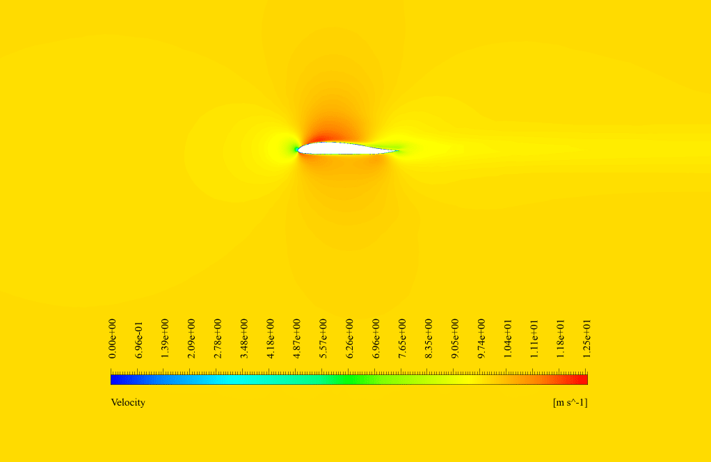
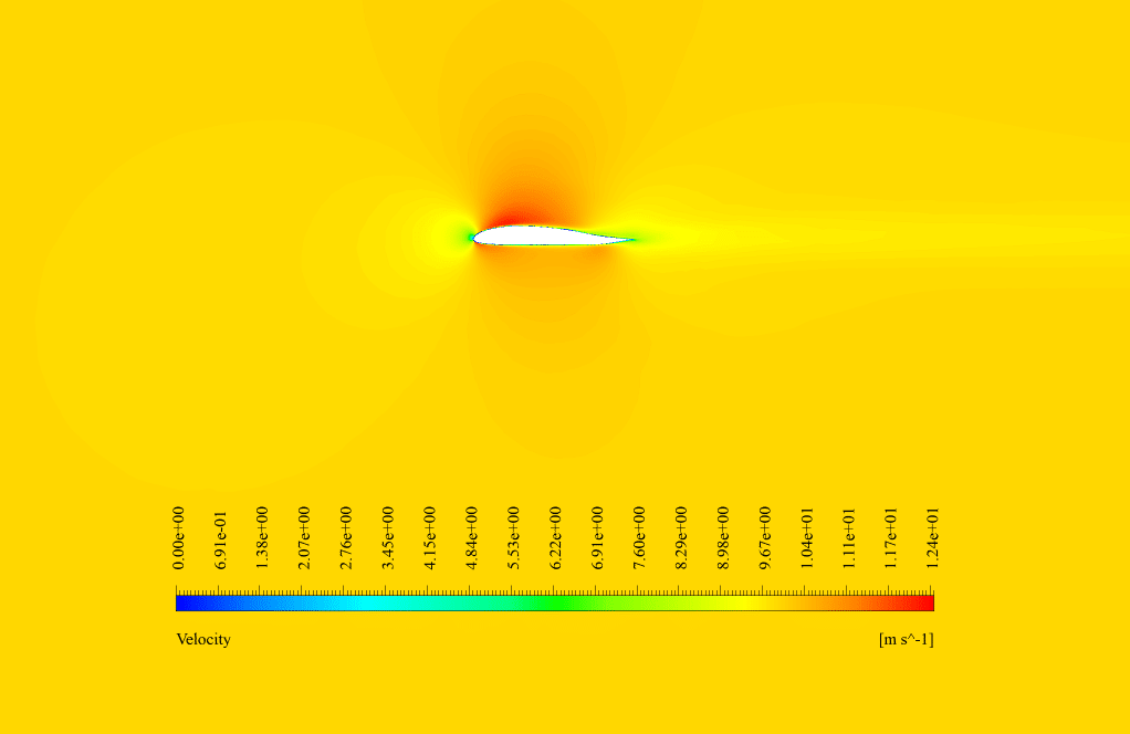
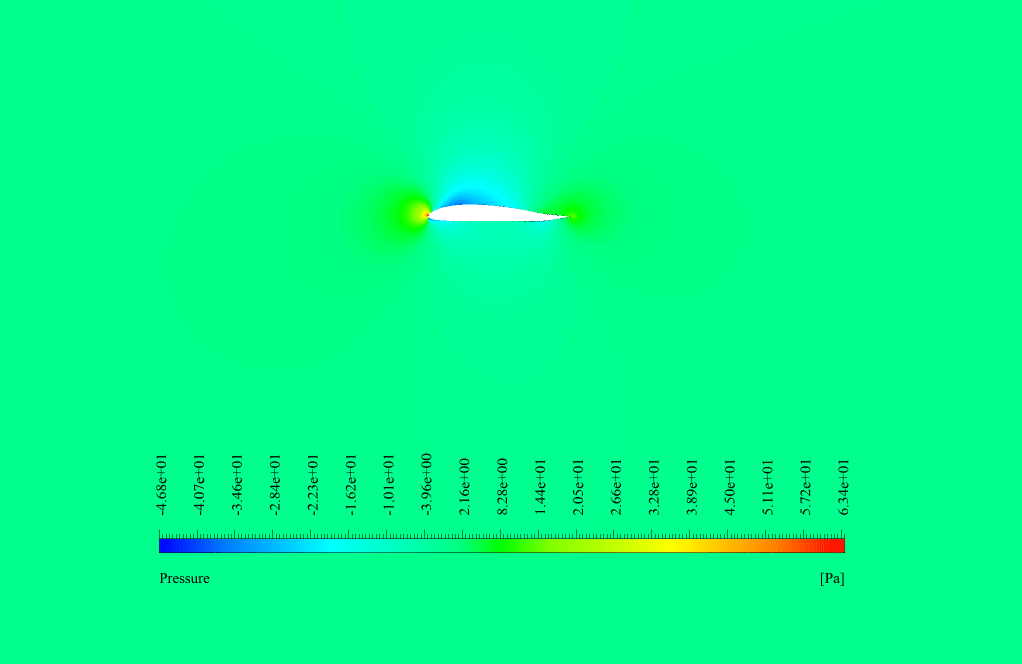
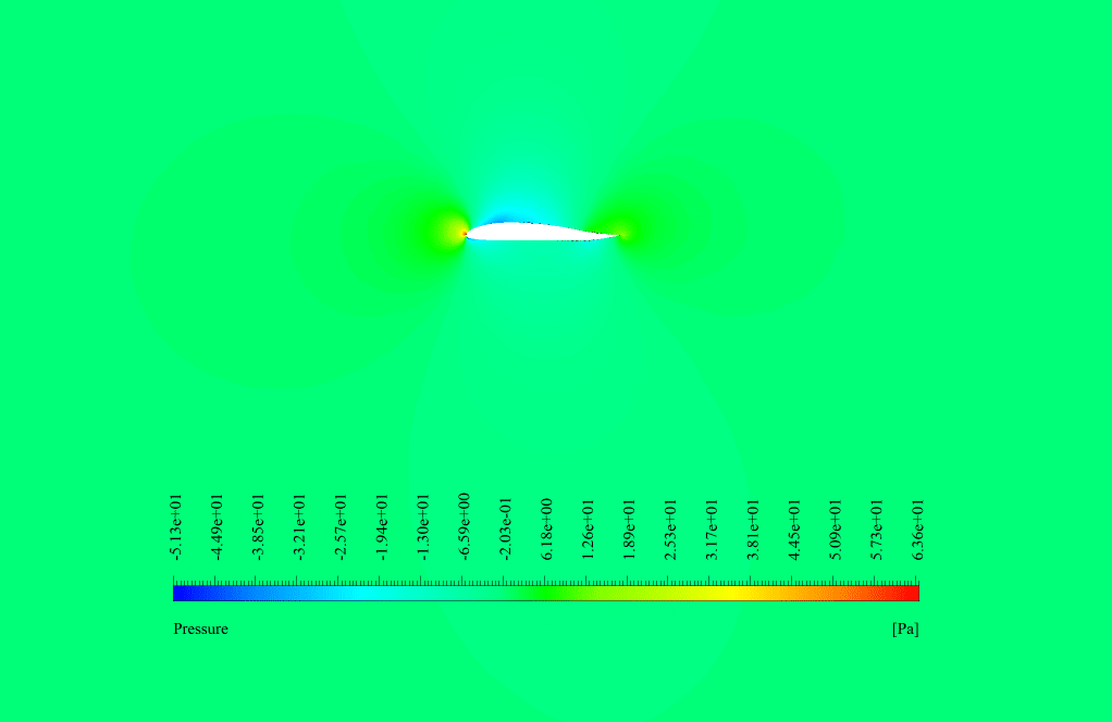
In conventional flow simulation, we obtained velocity and pressure contours. These contours showed the distribution of velocity and pressure inside the domain.
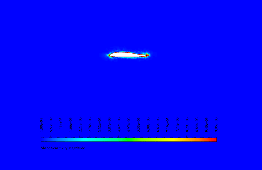
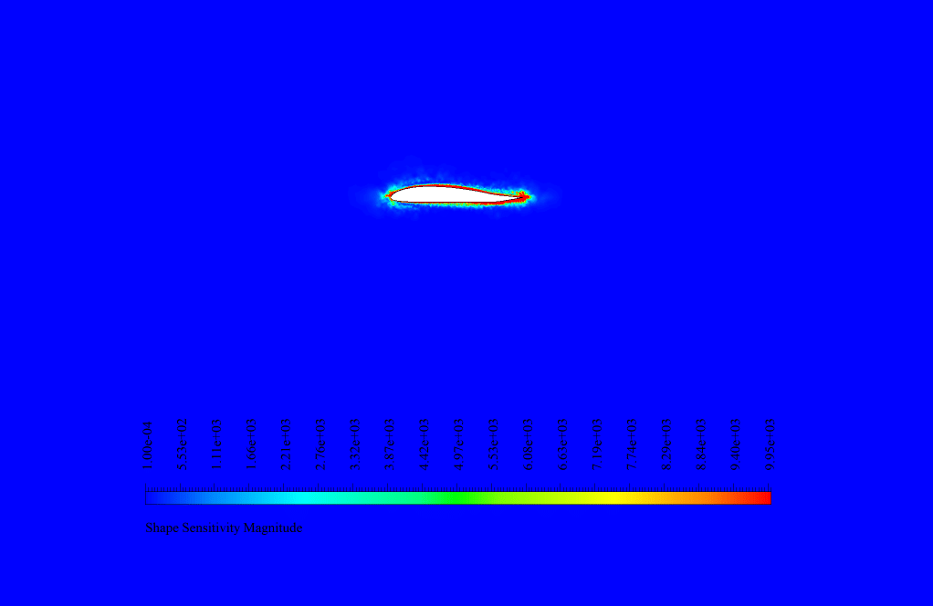
We analyzed the sensitivity in the adjoint solution. We obtained the shape sensitivity contour around the airfoil.
The highest sensitivity is shown at the trailing edge of the airfoil. This means that boundary displacement and shape deformation in these areas have the greatest effect on the amount of lift to drag ratio.
So to increase the ratio, we need to focus on the airfoil’s trailing edge. In the final solution by the gradient-based optimizer, the geometry undergoes deformation.
This displacement and deformation lead to the maximization of the ratio. The lift-to-drag ratio before optimization was equal to 0.34677032. After performing the second and third steps, this ratio reached the value of 2.0979013. So we conclude that the lift-to-drag ratio has increased by 83 %.
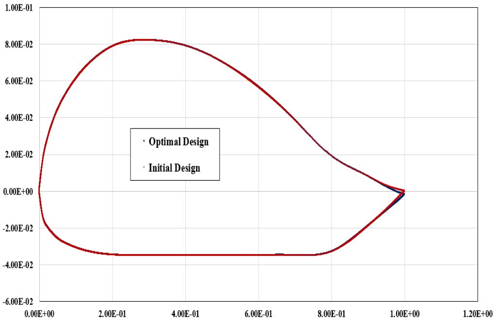
Also, we displayed the graph of the location of different points in two states: initial and optimal design. We can see the shape deformation and boundary displacement. The maximum boundary displacement is equal to 1.68049e-4 m, and the average displacement is equal to 1.90683e-5 m.
Finally, we can say that we achieved our goal, and the lift-to-drag ratio was increased with the design optimization method.


Lina Langosh Sr. –
This tutorial seems very comprehensive for understanding the optimization of the lift to drag ratio. Can you tell me more about how the mesh morphing technique contributed to the overall optimization process in this simulation?
MR CFD Support –
The mesh morphing technique, particularly using the Radial Basis Functions (RBF) method, played a crucial role in the optimization process for the airfoil design in this simulation. It allowed for the mesh around the airfoil to be adjusted following the design changes indicated by the sensitivity analysis. This mesh adaptation was essential to ensure an accurate flow solution around the newly optimized geometry of the airfoil. As a result, this technique contributed to achieving a higher lift-to-drag ratio, demonstrating the effectiveness of the optimization process.
Alberto Upton –
I am curious about the simulation’s sensitivity analysis. How do the areas identified as highly sensitive in shape sensitivity influence the lift to drag ratio? And how are those areas prioritized for optimization by the adjoint solver?
MR CFD Support –
The highly sensitive areas in shape sensitivity indicate regions where small geometric changes can significantly impact the lift to drag ratio. The adjoint solver prioritizes these areas by calculating how variations in the shape will affect the objective function, which in this case is to maximize the lift to drag ratio. Optimization techniques are then focused on these regions to fine-tune the airfoil design, ensuring improved aerodynamic performance with the most impact coming from changes made in these high-sensitivity areas.
Hester Hirthe –
Is it possible to customize the optimization process for other performance parameters like sound generation or fuel consumption?
MR CFD Support –
Absolutely, the adjoint solver and gradient-based optimizer in ANSYS Fluent can be tailored to focus on various performance parameters such as sound generation or fuel efficiency. The process would involve defining the relevant observable or operation in the solver to reflect the performance metric of interest, followed by sensitivity analysis and optimization to achieve the desired outcomes.
Nick Bednar –
I encountered some trouble understanding how the airfoil’s geometry changed during the optimization. Could you shed more light on that?
MR CFD Support –
In the optimization process, the airfoil’s geometry was adjusted based on the sensitivity data from the adjoint solver. Most of the modification focused on the trailing edge of the airfoil, where sensitivity analysis indicated the potential for the greatest impact on lift-to-drag ratio. The changes were executed through a Mesh Morphing technique using Radial Basis Functions (RBF), which allowed the mesh to deform smoothly to realize the new shape that increases the efficiency of the lift-to-drag ratio.
Candida Padberg –
The gradient-based optimizer managed to increase the lift-to-drag ratio by 83%! It’s impressive to see such substantial performance gains attributed to smart computational design and optimization. Well done!
MR CFD Support –
Thank you so much for your positive feedback! We are thrilled to hear that you are impressed with the performance improvements achieved through our optimization process. Our team works hard to provide effective and advanced CFD solutions, and it’s gratifying to know that our efforts are appreciated. If you have any further questions or need assistance with other simulations, feel free to reach out to us!
Dr. Claude Renner IV –
Can you clarify what exactly is meant by ‘Operation’, and how it relates to the observable in the simulation?
MR CFD Support –
In this simulation, an ‘Operation’ refers to a mathematical equation composed of different ‘Observables’ which are the output parameters monitored during the CFD analysis such as lift and drag. The ‘Operation’ defined in this case is the lift-to-drag ratio, which is a combination of lift (the upward force) and drag (the resistance force opposite to the airflow). The adjoint solver uses this operation to determine how changes in the airfoil’s shape will impact this specific ratio, guiding the optimization process towards designs that will maximize this value.
Dr. Nick Heathcote –
This tutorial was top-notch! Learned a lot about sensitivity analysis and optimization in aerodynamics using adjoint solver and RBF. The gradual improvement from the initial design to the final optimized shape was quite impressive. The increase in lift-to-drag ratio by 83% really showcases the efficiency of this method.
MR CFD Support –
Thank you for your positive feedback! We’re delighted to hear the tutorial exceeded your expectations and provided valuable insights into optimizing aerodynamic performance with ANSYS Fluent. It’s great to see our customers achieving such significant improvements in their simulations.
Carolanne Rempel –
I’m amazed by the optimization process and the increase of the lift-to-drag ratio by 83%. Great tutorial on using the adjoint solver and RBF together!
MR CFD Support –
Thank you for the positive feedback! We’re thrilled to hear that the tutorial on optimizing the airfoil’s performance using the adjoint solver and radial basis function mesh morphing was helpful and impressive. If you have any more questions or need further assistance, feel free to reach out!
Prof. Shayne Conroy –
Beyond increasing the lift-to-drag ratio, does the modification of the airfoil lead to any negative consequences, such as increased structural stress or decreased stability?
MR CFD Support –
In most optimization cases, focusing solely on aerodynamic properties like the lift-to-drag ratio could potentially lead to adverse effects on other aspects such as structural integrity. However, it’s important to note that in this specific simulation’s scope, only aerodynamic performance was examined. To fully understand the implications of the design changes, further analysis integrating structural evaluations would be necessary.
Miss Carley Dach III –
I learned a tremendous amount from your Adjoint Solver tutorial using ANSYS Fluent. One question that came to my mind was, how do you ensure mesh quality during the optimization process since the geometry of the airfoil changes?
MR CFD Support –
During the optimization process using the adjoint solver, we ensure mesh quality by using the Mesh Morphing technique. In the project, Radial Basis Functions (RBF) was the selected method for mesh morphing, which interpolates mesh deformation based on control points. This approach allows the mesh to be modified smoothly along with the geometry changes, preserving the mesh quality throughout the design changes. If there is a significant alteration in geometry, the mesh is adapted accordingly to maintain the desired aspect ratios, skewness, and overall element quality necessary for accurate CFD analysis.
Letha Corwin –
I found the part about increasing the lift-to-drag ratio particularly intriguing. Is it common to see an 83% improvement in the lift-to-drag ratio with this kind of simulation, or is this an exceptional case?
MR CFD Support –
Typically, an 83% improvement in the lift-to-drag ratio is considered exceptional and is not commonly observed. Each case is unique and improvements depend on the initial design and the scope for optimization. This significant improvement indicates that the original airfoil design had considerable room for enhancement or that an innovative approach in the optimization process was employed.
Kristy Kling –
What specific features of the RBF Morph technique were advantageous in optimizing the airfoil shape in this project?
MR CFD Support –
The RBF (Radial Basis Functions) Morph technique was leveraged for its ability to achieve smooth and continuous deformation of the mesh around the airfoil. Its interpolation from control points allowed for precise adjustments in geometry that targeted the areas with the highest sensitivity according to the adjoint solver results. This enabled a focused optimization process, enhancing the lift-to-drag ratio significantly without compromising the mesh quality.
Ms. Candace Larkin –
I’m truly astonished by the impressive lift-to-drag ratio improvement! Can you detail how sensitivity in the trailing edge influences the mitigation of the drag? It sounds like meticulous engineering without compromising lift.
MR CFD Support –
Indeed, the trailing edge significantly affects the aerodynamic efficiency of an airfoil as it’s a critical point for flow separation, which can contribute to drag. Sensitivity there signifies that even slight modifications to its geometry can have substantial effects on the flow characteristics, predominantly on boundary layer behavior, thus reducing drag while preserving or even enhancing lift. Ingenious tweaks here involve designing a smoother or sharper edge, amending its curvature or angle relative to the flow, all carefully balanced to retain optimal aerodynamic performance.
Rosamond Russel –
Fantastic tutorial! Maximizing lift-to-drag ratio has always been the quintessence for aerodynamic finesse and seeing it practically applied with a gradient-based optimizer is brilliant. Combining the depth of Ansys Fluent’s computational ability with a clear progression through conventional simulation, sensitivity analysis, and design adjustment is commendable. This certainly enabled a practical grasp of the implications each modification has on airfoil performance. Cheers to a well-crafted tutorial that enhances both understanding and application in aerodynamics optimization!
MR CFD Support –
Thank you so much for your positive review! We’re thrilled to hear that the tutorial was able to articulate the complexity of maximizing the lift-to-drag ratio in such an engaging and informative manner. It is our pleasure to provide content that helps our users effectively apply sophisticated CFD techniques to optimize aerodynamic performances. If you have further feedback or need assistance with anything else, we’re always here to help!
Prof. Minerva Toy –
What is the primary observable targeted for optimization in this simulation?
MR CFD Support –
In this simulation, the primary observable targeted for optimization is the lift-to-drag ratio of the airfoil. The adjoint solver’s goal was to maximize this ratio through design modifications.
Dr. Mckayla Witting MD –
I am thrilled by the improvement achieved through the use of the adjoint solver and RBF Morph – an 83% increase in lift-to-drag ratio is impressive! The balance between lift and drag is crucial in any aerodynamic design, and high efficiency in this area spells significant progress.
MR CFD Support –
Thank you for sharing your positive experience! It’s great to hear that our product helped you appreciate the importance of achieving a good balance between lift and drag, which is indeed key in aerodynamic designs. Your appreciation motivates us to keep creating high-quality, informative tutorials. If you need any further assistance or have more questions, feel free to reach out!
Aiyana Murazik –
The optimization results seem amazing! Has this optimized airfoil design been validated through wind tunnel testing or any similar real-world verification method?
MR CFD Support –
We appreciate your interest in the final results of the airfoil optimization through CFD simulation! As for the real-world validation, such verification would indeed be critical for ultimate confirmation of the performance improvements. However, the provided description does not include information regarding any follow-up wind tunnel tests or real-world validation efforts. CFD simulations, like the one described for the airfoil, typically serve as a preliminary step to identify potential improvements before more expensive and time-consuming physical experiments are conducted.
Dr. Jesse Graham DDS –
What are the improvements in airfoil performance after optimization with the gradient-based optimizer, and how are these changes visualized in the results?
MR CFD Support –
Through the use of the gradient-based optimizer in combination with Adjoints analysis, we successfully increased the airfoil’s lift-to-drag ratio by 83%, massively enhancing its aerodynamic efficiency. These improvements were visually presented in the simulation outcomes, visibly depicting alterations in airfoil contour through velocity and pressure distribution before and after optimization. Additionally, graphs showcasing positional shifts pinpointed significant boundary displacements, crucial to maximizing performance.
Ana Bogisich –
I am so impressed with the lift-to-drag optimization results! Using CFD to enhance aerospace design is truly fascinating!
MR CFD Support –
Thank you for your positive feedback! We’re delighted to hear that you found the lift-to-drag ratio optimization informative and that it sparked your interest in aerospace design. CFD is indeed a powerful tool for such advancements. We appreciate your appreciation and hope our learning products continue to inspire you!
Rogelio Hermiston IV –
Great tutorial! I was impressed by how much the lift-to-drag ratio improved with the optimization method. The explanations were clear, and the step-by-step approach really helped understand the application of the adjoint solver and RBF mesh morphing. Kudos to the MR CFD team for creating such an informative and practical guide.
MR CFD Support –
Thank you for your positive feedback! We’re thrilled to hear that you found the tutorial on Maximizing Lift to Drag Ratio informative and that the guidance on using the adjoint solver and RBF mesh morphing was clear and helpful. Your appreciation means a lot to us and motivates our team to continue creating high-quality CFD learning materials.
Madge Grady –
The review regarding the lift to drag ratio improvement using the adjoint solver in ANSYS Fluent is fascinating. How long does it typically take for such a simulation to run from start to finish, including the optimization process?
MR CFD Support –
The duration of the simulation and optimization process depends on several factors including the complexity of the geometry, the quality of the mesh, the constraints of the optimization, computational resources, and the specific settings of the adjoint solver. It may vary from a few hours to several days. For personalized details regarding the timeframe for your particular simulation, please consult with one of our expert CFD consultants.
Kian Kerluke –
The adjoint solver analysis was very informative. It’s incredible to see sensitivity concentrated at the airfoil’s trailing edge and how this pinpointed where to focus design modifications effectively, leading to such a substantial improvement in lift-to-drag ratio. Congrats on achieving an 83% increase through optimization – that’s quite impressive!
MR CFD Support –
Thank you for your feedback! We’re thrilled to hear you found the use of the adjoint solver analysis informative and effective in optimizing the airfoil design. It’s always exciting to see our technology being used to enhance aerodynamic performance significantly. We deeply appreciate your comments and are glad you found success with our tutorial.
Emilie McDermott Jr. –
I found the section on the mesh morphing methods particularly intriguing. Could you detail how the radial basis functions contribute to achieving the optimal airfoil shape in terms of aerodynamic performance?
MR CFD Support –
In this context, Radial Basis Functions (RBF) are used to deform the mesh smoothly during the optimization process, ensuring that the geometry alterations that increase the lift-to-drag ratio don’t compromise the mesh quality. The control points determine specific locations where deformation occurs, and the interpolation ensures a coherent change across the mesh. By methodically refining the airfoil contour at areas of highest shape sensitivity, RBF contributes to enhancing the aerodynamic performance by incrementally maximizing the targeted lift-to-drag ratio.
Dr. Deonte Runolfsdottir –
The results mention an 83% increase in lift-to-drag ratio after optimization. Is this the usual level of improvement one can expect using this method, or is it specific to this setup?
MR CFD Support –
The level of improvement in lift-to-drag ratio using an Adjoint Solver with a gradient-based optimizer can vary greatly depending on the specific design and how optimized the initial model is. The 83% improvement reported in this simulation is specific to this setup and may not necessarily be representative of other simulations or real-world scenarios. Factors such as the initial airfoil design, the range of allowable shape modifications, and the flow conditions can influence the potential improvements achieved.
Aron Donnelly –
What an insightful tutorial on maximizing the lift to drag ratio using the adjoint solver method and gradient-based optimization! It’s clear that the detailed sensitivity analysis focusing on shape sensitivity played a crucial role in improving the airfoil design. The use of RBF Mesh Morphing appears particularly effective for this application. It’s great to see how computational methods like these can lead to such significant improvements in aerodynamic performance.
MR CFD Support –
Thank you for your positive feedback! We’re glad to hear that you found the tutorial insightful and could appreciate the effectiveness of RBF Mesh Morphing and the adjoint solver method. It’s always rewarding to see our customers recognize the value of these advanced optimization techniques. If there’s anything else you’d like to explore or learn about, don’t hesitate to reach out to us for more information. Thank you for choosing MR CFD for your learning experience!
Donnell O’Hara II –
I’ve recently completed the airfoil optimization tutorial using the Adjoint Solver and RBF Morphing. The outcome is stunning! The detailed procedure for sensitivity analysis and geometry deformations really helped me grasp the complexities of aerodynamic optimization. The iterative improvements in lift-to-drag ratio were truly illustrative of the potent capabilities ANSYS Fluent possesses. Thank you for such an insightful and practical tutorial!
MR CFD Support –
We’re absolutely thrilled to hear such positive feedback on our airfoil optimization tutorial using the Adjoint Solver and RBF Morphing. Understanding that the lessons on sensitivity analysis and the demonstration of geometry deformation had a significant impact on your learning experience makes all the effort worthwhile. We appreciate you highlighting how ANSYS Fluent’s dynamic tools facilitated an impressive enhancement in performance through lift-to-drag ratio improvements. Thank you for your appreciation and for choosing our tutorial to expand your knowledge.
Brianne Gulgowski –
I’ve followed your training for optimizing the lift-to-drag ratio using the adjoint solver. Can you tell me about the computational resources required for simulations like these, specifically with respect to the CPU and RAM?
MR CFD Support –
For simulations utilizing the adjoint solver for optimizing lift-to-drag ratio, the computational resources would depend on the complexity of the model, the number of cells in your mesh, and the convergence criteria set for the simulation. As an approximation, for a model with around 200,000 cells, you’d require a moderate to high-performance CPU (Multi-core processor) and at least 16 GB of RAM to run the simulation efficiently. However, larger or more complex simulations may need more advanced computational resources.