Minimizing Drag Force by Adjoint Solver (RBF), ANSYS Fluent CFD Simulation Training
$150.00 Student Discount
- The problem numerically simulates the drag force on a simple cylindrical obstacle using ANSYS Fluent software.
- We design the 2-D model by the Design Modeler software and then mesh it with ANSYS Meshing software.
- The mesh type is Structured, and the element number equals 36000.
- We aim to Minimize the drag force in a three-step simulation.
- We use the Adjoint Solver to analyze the Shape Sensitivity.
- The Design Optimization is performed with the Gradient-based Optimizer.
- We use the Radial Basis Function (RBF) to apply Mesh Morphing.
To Order Your Project or benefit from a CFD consultation, contact our experts via email ([email protected]), online support tab, or WhatsApp at +44 7443 197273.
There are some Free Products to check our service quality.
If you want the training video in another language instead of English, ask it via [email protected] after you buy the product.
Description
Description
This project is related to the numerical simulation of the Drag force on a simple Cylindrical obstacle using Ansys Fluent software. We aim to optimize the Design of this model using an Adjoint Solver and Gradient-Based Optimizer.
Such modeling is done in Three stages. First, we perform the conventional flow simulation. In the second step, we analyze the Sensitivity with the adjoint solver. Finally, we change the model’s design to achieve Optimal performance with the gradient-based optimizer.
The adjoint solver provides a series of data that is expressed in the form of sensitivity analysis. We focus on Shape sensitivity.
This tool identifies which areas of the geometry have the greatest influence on system performance.
So we need to define a target parameter. This output parameter is called Observable. In the present work, we have defined the drag force as observable.
So, the adjoint solver is based on the drag force applied to the cylinder. Wherever more sensitivity is shown, i.e., Displacement of the boundary or Deformation of the shape of the design, it has a greater effect on the drag force.
We use the sensitivity analysis data in the gradient-based optimizer. In this tool, we specify how the observable should be changed. For example, in this project, we consider Decreasing the drag force. This means changing the cylindrical geometry to Minimize the drag force. These changes should lead to an optimal design.
We modeled the geometry of the project using Design Modeler software. This model is the computational zone around a cylinder. For simplicity, we assumed the geometry to be two-dimensional and only modeled the circular cross-section of the cylinder.
Then we meshed the model with Ansys Meshing software. The mesh type is Structured, and the number of cells equals 36000.
Adjoint Solver Methodology
We used the adjoint solver in this project to obtain the sensitivity data. For this purpose, we defined the drag force (horizontal force caused by water flow) as observable.
We then used the sensitivity data to solve the gradient-based optimizer. Before solving the gradient-based optimizer, we performed some settings in the Design Tool tab.
In the section of the zone to be modified, we determined the entire circular wall for deformation.
Then we created a square shape Region around this circular wall. We considered this square an area of the domain where geometry and mesh changes are supposed to occur.
When the shape is deformed, and its boundaries are moved, the mesh around this area changes.
To apply mesh changes, we used the Mesh Morphing technique. There are three methods for mesh morphing: polynomial, direct interpolation, and Radial Basis Functions (RBF).
In this project, we used RBF for mesh morphing. For the radial basis function, the mesh deformation is interpolated from the control points.
In the Objective part, we determined the value of observable changes. In this way, the drag force will Decrease by thirty percent.
We set the Design Number to Ten, so we can see a thirty percent reduction in the drag force in the ten stages.
Adjoint Solver Conclusion
As we said, the present simulation is done in three consecutive steps. So we investigated the results in three steps.
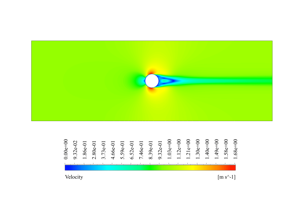
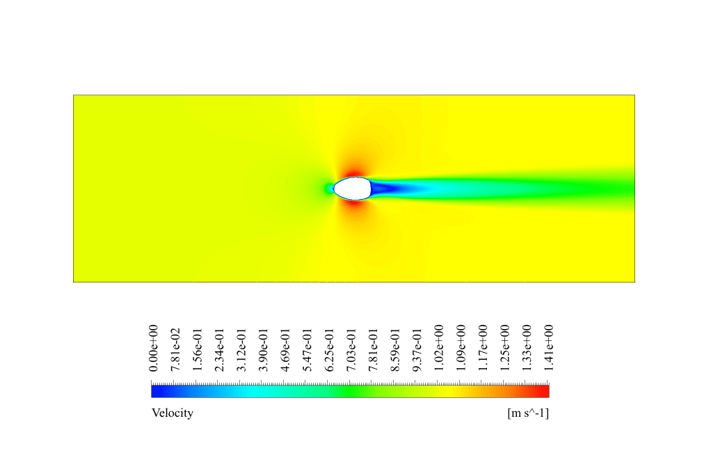
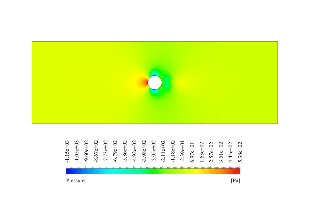
In conventional flow simulation, we obtained velocity and pressure contours. These contours showed the distribution of velocity and pressure inside the domain.
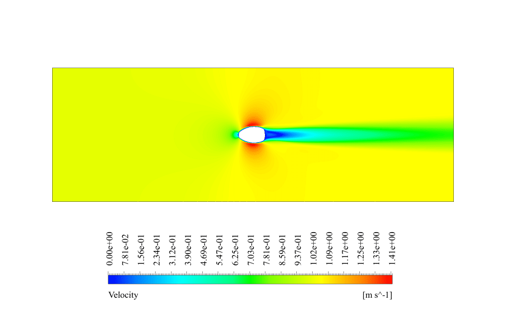
The pressure contour shows that the highest pressure appears in front of the cylinder, as it is directly in the water flow path. The velocity contour also shows a wake behind the cylinder caused by fluid separation.
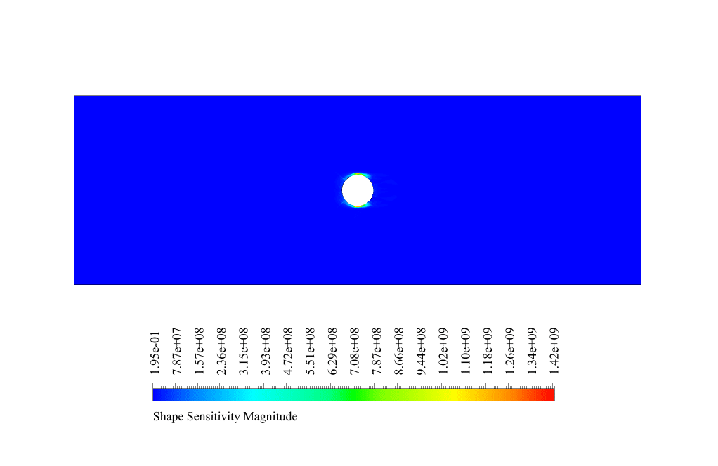
We analyzed the sensitivity in the adjoint solution. We obtained the shape sensitivity contour around the cylinder.
The highest sensitivity is shown in the upper and lower parts of the cylinder. This means that boundary displacement and shape deformation in these areas have the greatest effect on the amount of drag force.
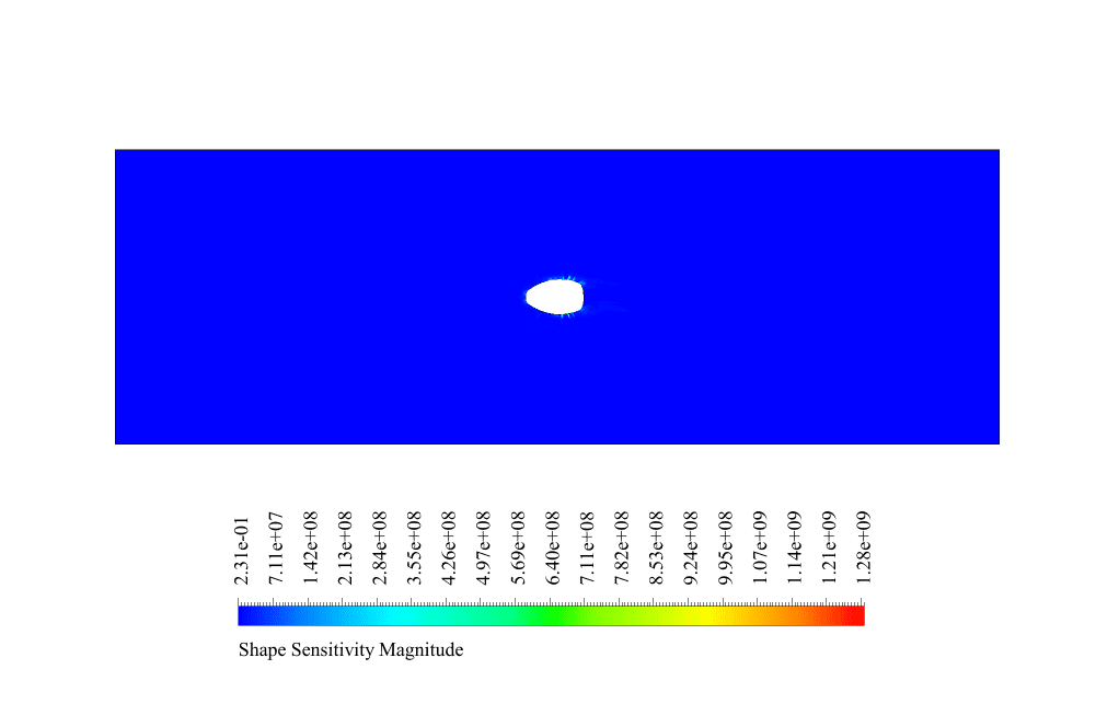
So to reduce the drag force, we need to focus on the upper and lower parts of the geometry. In the final solution by the gradient-based optimizer, the geometry undergoes deformation.
This displacement and deformation lead to the minimization of the drag force. The drag force before optimization was equal to 2.6684692 N. After performing the second and third steps, this force reached the value of 0.78095984 N. So we conclude that the drag force has decreased by 70 %.
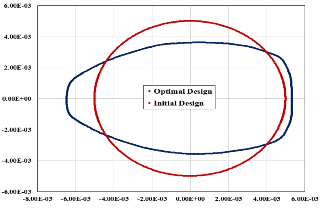
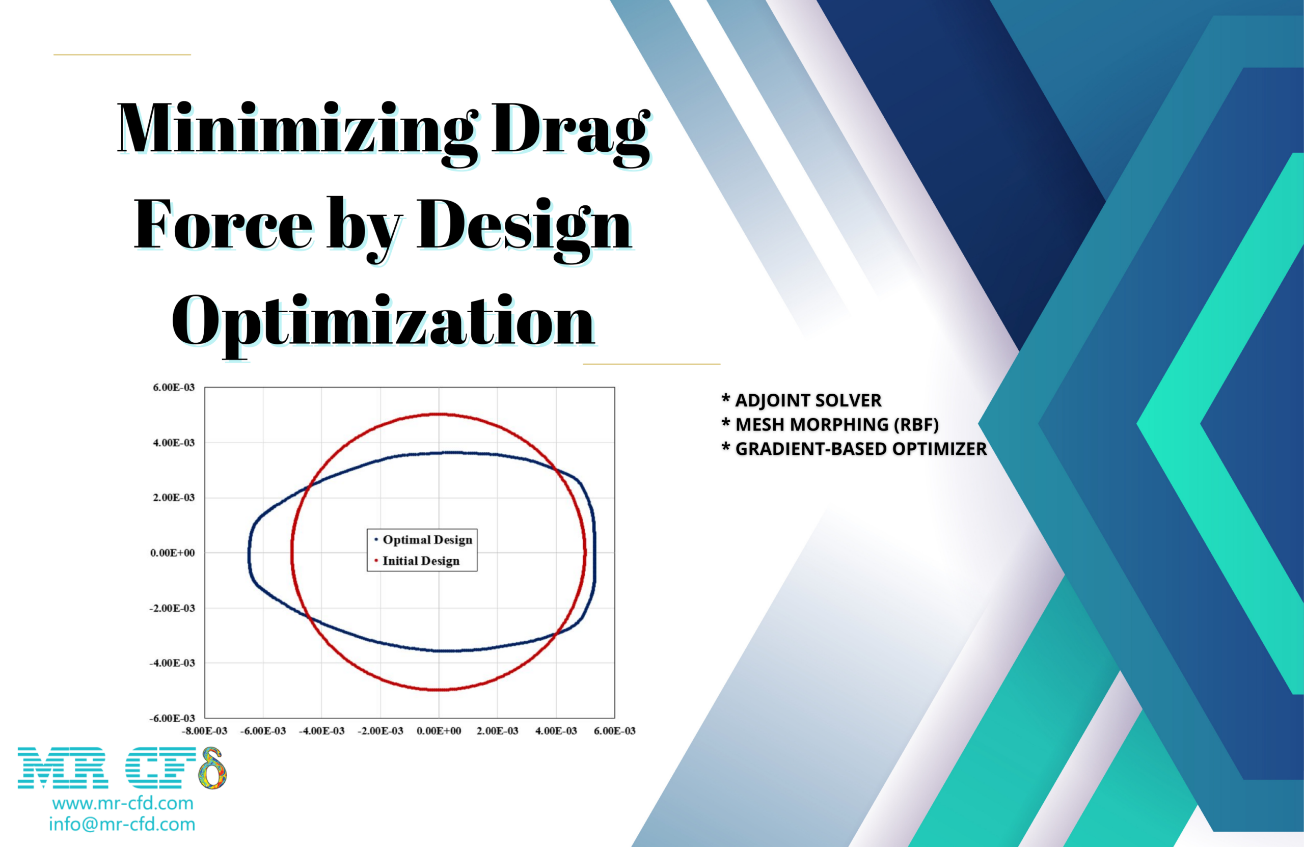
Also, we displayed the graph of the location of different points in two states: initial and optimal design. We can see the shape deformation and boundary displacement. The maximum boundary displacement is equal to 3.65042e-5 m, and the average displacement is equal to 1.75812e-5 m.
The comparison of designs shows that the cross-section perpendicular to the flow should be smaller to reduce the drag. So the model has partial elongation.
Finally, we can say that we achieved our goal. We reduce the drag force with the design optimization method.

Hermann Bins –
I’m thrilled with the results of the CFD Project on minimizing drag force with the RBF Morph technique! It has significantly helped me understand the optimization process. However, I am curious if varying the flow conditions, such as using a different liquid with various properties or changing the flow velocity, would greatly affect the optimal shape found in this simulation or if the shape is universally optimal regardless of these conditions.
MR CFD Support –
Thank you for the compliment! To answer your question, varying the flow conditions, such as fluid properties or flow velocity, can indeed influence the optimal shape for drag reduction. The optimal shape derived using CFD considers the specific scenarios simulated, including the fluid characteristics and flow conditions. If these vary substantially from the scenario tested, it may be necessary to conduct a new optimization process to account for the altered conditions and achieve the best performance. We always recommend reassessing the optimization if the operating environment changes.
Rhoda Weissnat –
After the shape optimization, does the flow reattach more smoothly behind the optimized cylindrical obstacle, in comparison to the original geometry?
MR CFD Support –
Yes, after the optimization process using adjoint solver and morphing techniques, the optimized geometry is designed to minimize the drag force which typically leads to smoother flow reattachment behind the obstacle as compared to the pre-optimization geometry. The flow separation is reduced, and this results in a more streamlined geometry with a smaller wake area, leading to lower drag.
Maryam Yundt Jr. –
The results after using the adjoint solver and the gradient-based optimizer are outstanding! The drag force decreased by 70%, which is impressive. The details on design sensitivity and the focus area for reducing drag have provided significant insights. This training solidly demonstrates the power of optimization in fluid dynamics.
MR CFD Support –
Thank you so much for sharing your positive experience with our CFD Simulation Training. We’re glad to hear that the content was insightful and that the impressive results of the drag force reduction through optimization techniques stood out for you. Your feedback is greatly appreciated and it motivates us to continue providing high-quality educational materials. Thank you for choosing our training course on mesh morphing using RBF Morph (Mesh Morphing) and Adjoint solver methodologies.
Dr. Otilia Weber III –
In the conclusion, the final drag force appears significantly reduced. Could you confirm if this decrease corresponds with the expected target of a 30% reduction, and how consistent were the final outcomes with the ten iterations of the design number set in the objectives?
MR CFD Support –
The decrease in drag force by 70% actually exceeds the expected target of 30%. According to the final outcomes provided, the reduction in drag force is consistent with the design changes made through the ten iterations, showing that the sensitivity analysis and shape optimization were effective in achieving optimal performance beyond the initial target.
Mrs. Burdette Kessler DVM –
What were the specific design modifications made to the cylinder to achieve the 70% reduction in drag force?
MR CFD Support –
The specific design modification implemented was elongating the cross-section perpendicular to the flow, effectively reducing the size of the face that meets the water current. The deformation largely occurred at the upper and lower parts of the cylinder, which were identified as areas of high sensitivity. This reshaping of the cylinder minimized the drag force as dictated by the adjoint solver’s sensitivity analysis.
Stephan Boyer –
What observable parameter is defined in detailed adjudication during the sensitivity analysis with the adjoint solver?
MR CFD Support –
In this project, the defined observable parameter during sensitivity analysis with the adjoint solver is the drag force applied to the cylinder.
Miss Jordane Koch –
After the optimization, is the adjusted model specifically shaped to minimize drag for just this specific flow condition, or can it be generalized for various flow conditions?
MR CFD Support –
The optimized model is shaped to minimize drag for the specific conditions established in this simulation. It is tailored to the defined fluid properties, flow characteristics, and geometry constraints within the simulation parameters. For different flow conditions, such as changes in velocity, density, or flow direction, the model would likely require further optimization to achieve minimal drag.
Stephon Schmidt –
What strategies are employed for mesh morphing in this project, and why was RBF selected?
MR CFD Support –
In the project, three methods for mesh morphing were discussed: polynomial, direct interpolation, and Radial Basis Functions (RBF). RBF was selected due to its ability to efficiently interpolate mesh deformation from control points. This allows for an optimal reshaping of the mesh around the deforming geometry to reduce the drag force effectively as adjustments occur.
Rae Bednar Sr. –
I am impressed with the drag reduction of 70% achieved through the optimization steps. Could you point out which part of the geometry has the most significant change as a result of the optimization?
MR CFD Support –
Thank you for your kind words! The most significant geometry changes typically occur in the areas that the sensitivity analysis indicated as having the highest impact on drag. In this simulation, that would be the upper and lower parts of the cylinder that showed the greatest sensitivity to drag force. The geometry in these areas is fine-tuned to create a profile that minimizes pressure differences and flow separation, leading to considerable drag reduction.
Bethany Jerde II –
The project on drag reduction is quite insightful. It’s clear that the customized use of the adjoint solver backed by gradient-based optimization can effectively decrease the drag force on a cylindrical obstacle. Impressive use of RBF for precise mesh morphing too!
MR CFD Support –
Thank you for your positive review and for acknowledging the strengths of the solver and mesh morphing techniques used in the drag reduction project. It is wonderful to hear that you found the insights useful and the approach effective. If you require further information or assistance with similar simulations, we would be happy to help.
Mrs. Catalina Dooley DDS –
I followed the 3-stage optimization process outlined in the course, but could you clarify how the observable was chosen as drag force? What are the factors considered when selecting an observable for the adjoint solver?
MR CFD Support –
The observable, in this case the drag force, is chosen based on the optimization goal. Factors considered for selecting an observable include understanding the performance metric most crucial to the system’s efficiency, the ease of its measurement or simulation, and its relevance to the desired outcome. Here, reducing drag was the target, hence the choice of drag force as the observable for conducting sensitivity analysis through the adjoint solver.
Prof. Monserrate Wyman DVM –
The results after optimization show a 30% drag force reduction. Why do we not see that the drag force reduced by 70% after the optimization steps?
MR CFD Support –
In the simulation description, it is mentioned that the drag force decreased by 70% after performing the optimization using the gradient-based optimizer. However, you’ve inquired about expecting a 30% reduction. The discrepancy possibly lies in the setting for the target reduction in the optimizer which was set to find a thirty percent reduction. Generally, the setting might constitute a target or an intermediate step—yet according to the text, the final observed reduction is 70%, indicating a more substantial optimization beyond the initial target expectation. If there’s any confusion or additional information required about the settings or the results, it’s always good to refer back to the documentation or guidance associated with the software for clarity.