Multi-Phase Flow in an Injector CFD Simulation
$80.00 Student Discount
- The problem numerically simulates an Injector using ANSYS Fluent software.
- We design the 3-D model by the Design Modeler software.
- We Mesh the model by ANSYS Meshing software, and the element number equals 102752.
- We use the VOF Multi-Phase model to define water and air in an injector.
Click on Add To Cart and obtain the Geometry file, Mesh file, and a Comprehensive ANSYS Fluent Training Video.
To Order Your Project or benefit from a CFD consultation, contact our experts via email ([email protected]), online support tab, or WhatsApp at +44 7443 197273.
There are some Free Products to check our service quality.
If you want the training video in another language instead of English, ask it via [email protected] after you buy the product.
Description
Multi-Phase Flow in an Injector CFD Simulation, ANSYS Fluent Tutorial
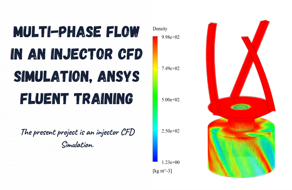
In this project, ANSYS Fluent software simulates Multi-Phase Flow in an Injector. We perform this CFD project and investigate it by CFD analysis.
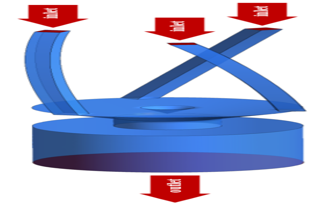
The present model is designed in three dimensions using the Design Modeler. Three ducts have a square cross-section for water flow, a conical-shaped area, and a cylindrical chamber. The meshing of the present project has been done using ANSYS Meshing software. The element number is 102752.
Injector Methodology
The VOF Multi-Phase model, which consists of air and water flows, is used. Water flows through three curved ducts into a reservoir that only has airflow inside its space.
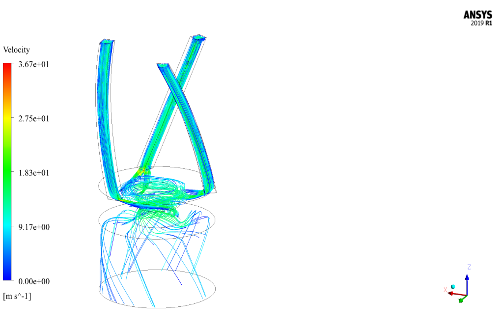
The curved structure of the ducts and the cone-shaped state on the air-filled tank distributes the water flow vortices into the injector, thereby discharging the water out of the surroundings of the cylindrical chamber (near the chamber wall) of the injector.
The water flow enters through the inlet boundary with a mass flow rate of 0.01kg/s. Moreover, the standard k-epsilon model is enabled to solve turbulent fluid equations.
Injector Conclusion
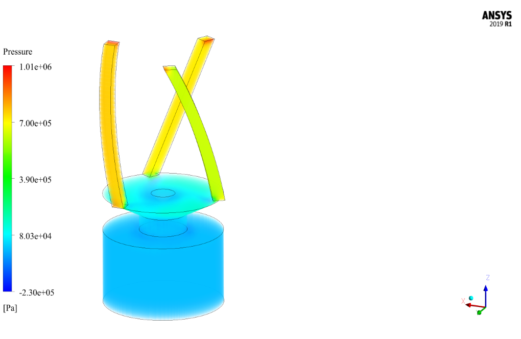
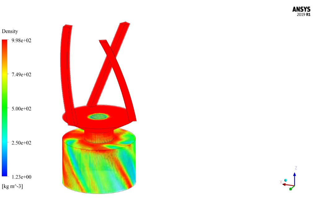
At the end of the solution process, two- and three-dimensional contours inside the injector are obtained related to the temperature, velocity, air and water volume fraction, streamlines, etc..
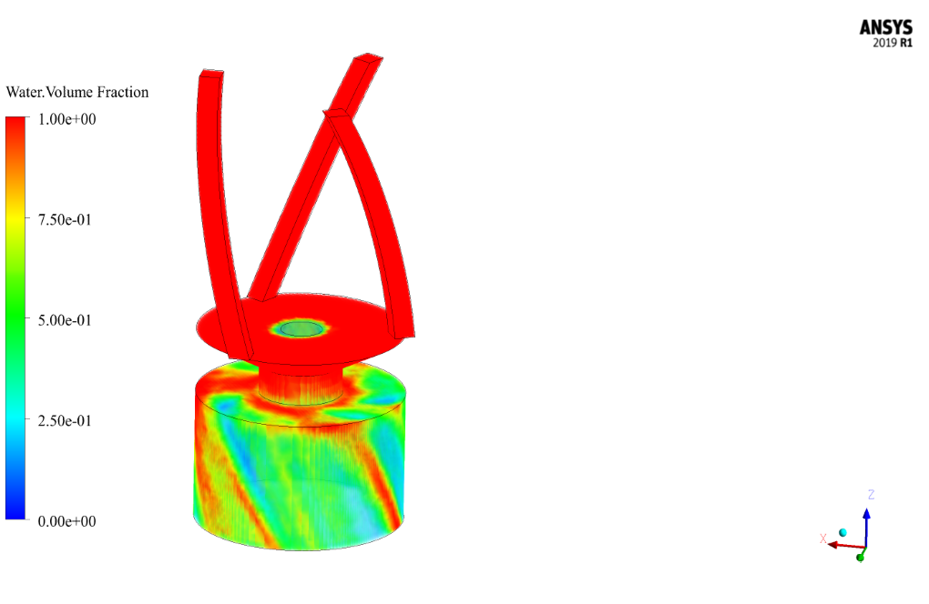
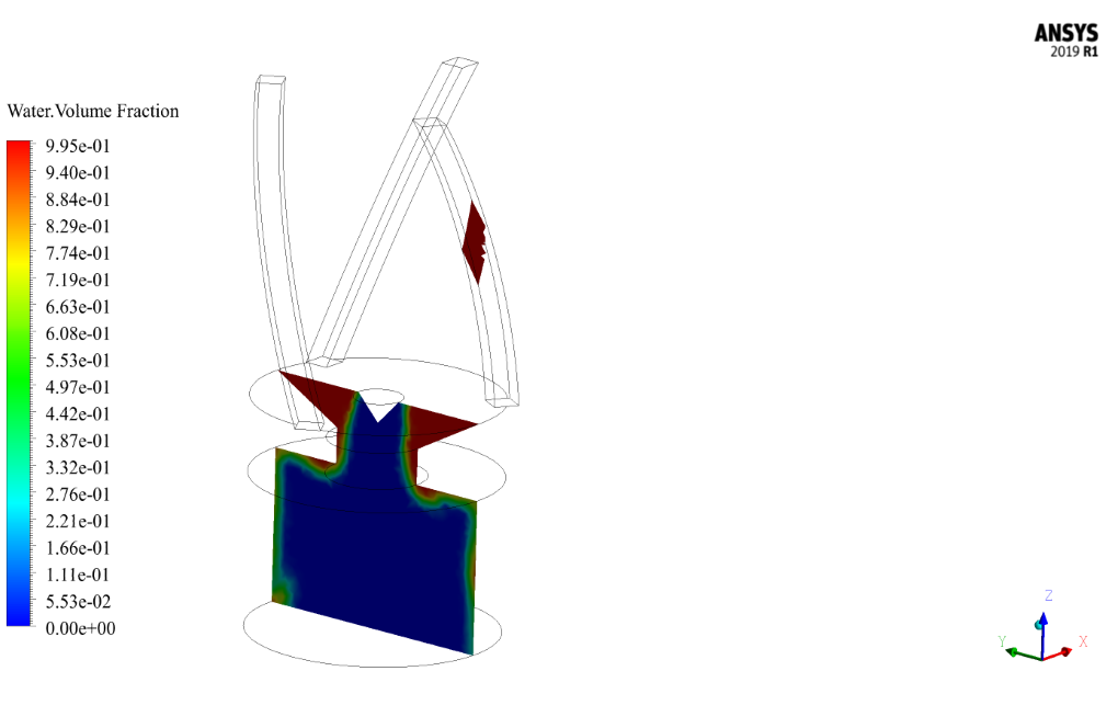
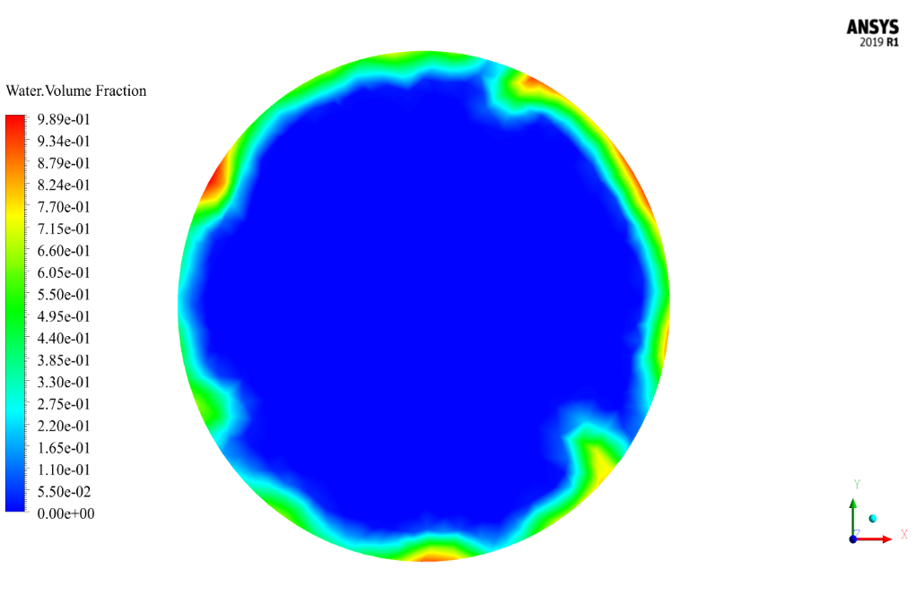
As seen in the water volume fraction contour, the water is injected through the curved channels and then flows through the cylindrical space. The curved channels cause a swirl in water flow, making sure the rotating flow pattern happens inside the cylindrical space.



Dr. Brendon Zulauf DVM –
How are the results of the simulation visualized?
MR CFD Support –
The results are visualized using contour plots of pressure and velocity, as well as pathlines of the flow.
Prof. Bulah Gusikowski V –
How does the simulation model the multi-phase flow in the injector?
MR CFD Support –
The simulation uses the Volume of Fluid (VOF) method to capture the interface between the liquid and gas phases in the injector.
Jaqueline Schamberger –
The tutorial for the multi-phase flow in an injector simulation was fantastic! I followed it step by step and the visualizations in ANSYS Fluent were especially helpful for my understanding of the fluid dynamics involved.
MR CFD Support –
Thank you for your positive feedback! We are thrilled to hear that our tutorial was helpful and that the visualizations enhanced your understanding of the simulation process. Our team works hard to produce clear and comprehensive learning materials, so your satisfaction means a lot to us. If you have any more questions or require further assistance with your CFD learning journey, do not hesitate to reach out.
Friedrich Kuphal –
I was completely satisfied with the tutorial on Multi-Phase Flow in an Injector using ANSYS Fluent. The explanation of the VOF model and how the flows interact within the confined space of the injector were clear and highly informative. Additionally, the demonstration of the ability to simulate complex vortex patterns created by the water’s movement through the injector’s curved channels was insightful. The use of visual aids like the contours related to the temperature and velocity helped in understanding the flow dynamics more precisely.
MR CFD Support –
We appreciate your positive feedback and are thrilled to hear that our tutorial met your expectations. Understanding the complexities of multi-phase flow within an injector is crucial for accurate simulations, and we’re glad that our visual representations and explanations enhanced your comprehension. Thank you for choosing our tutorial. If you have any further inquiries or need assistance with similar projects, please do not hesitate to reach out.
Merl Mueller –
The product description mentions a mass flow rate for water, but I’m wondering how airflow is handled in the simulation? Is it also introduced via a boundary condition?
MR CFD Support –
In the simulation, the airflow is indeed handled via boundary conditions. Air is introduced into the system at atmospheric pressure through the open space in the reservoir, allowing for the natural interaction between the water flow and the surrounding air within the injector chamber as per the VOF Multi-Phase model setup.
Jovany Aufderhar –
Can I contribute to this simulation?
MR CFD Support –
We are open to contributions! Please share your ideas or suggestions.
Brody Heller –
The tutorial was detailed and the provided information about multi-phase flow dynamics in an injector was clear. The CFD simulations and contour outputs generated were instrumental in understanding the complex interactions within the injector’s environment.
MR CFD Support –
Thank you for taking the time to share your feedback! We’re delighted to hear that our Multi-Phase Flow in an Injector CFD Simulation tutorial was helpful and informative. If you have any more questions or need further assistance with similar projects, feel free to reach out. Your success in mastering CFD simulations is what drives us!
Mrs. Nakia Brakus –
I just completed the ‘Multi-Phase Flow in an Injector CFD Simulation’ tutorial, and it was incredibly insightful. The motion of both air and water was clearly demonstrated, and I particularly enjoyed the detailed instructions on setting up the VOF Multi-Phase model in ANSYS Fluent. The step-by-step approach made it easy to follow along and learn how multiphase flows work in complex geometries. It’s great to see the injector’s internal flow dynamics visualized so clearly. Well done on creating such an informative and practical tutorial!
MR CFD Support –
Thank you so much for your positive review! We’re thrilled to hear that the tutorial was helpful and provided you with a clear understanding of multi-phase flows and their simulation in ANSYS Fluent. Your feedback is greatly appreciated, and we look forward to providing more quality learning materials. Keep exploring and happy simulating!
Dr. Richmond Legros –
I’m impressed with the detail in the simulation. Did the VOF model accurately capture the interface between the air and water flow in the injector?
MR CFD Support –
Thank you for the kind words! Yes, the VOF (Volume of Fluid) model is specifically designed for tracking and locating the interface between two immiscible fluids, like air and water in this case. This model effectively captures the interface dynamics and predicts the phase distribution within the injector accurately.
Lue Ledner –
The tutorial was thorough and insightful—I’m impressed by the VOF multi-phase modeling of the air and water flows. The visualization of how the curved channels influence flow patterns was particularly enlightening.
MR CFD Support –
Thank you for your positive feedback! We’re delighted to hear that our tutorial on multi-phase flow in an injector has provided you with clear and valuable insights, and that the visualization aspects greatly contributed to your understanding of the flow dynamics.
Solon O’Conner –
Wonderful tutorial on multi-phase flow in injectors! The details on the methodology and the insights from the conclusions help grasp complex phenomena easily. Your tutorials build a strong foundation for learners.
MR CFD Support –
Thank you so much for your positive feedback! We’re very pleased to hear that our tutorial on multi-phase flow in injectors was helpful to you. If you ever have more questions or need further clarification as you continue learning with our products, don’t hesitate to reach out. We’re here to support your learning journey!
Sabina Kunde –
This tutorial seems thorough! Impressed by the level of detail in the methodology, particularly the use of the VOF Multi-Phase model for air and water flows.
MR CFD Support –
Thank you for the positive feedback! We strive to provide detailed and comprehensive tutorials for a productive CFD learning experience. We’re glad you found the methodology, including the use of the VOF Multi-Phase model, informative and helpful.
Leone Brekke –
I’m impressed with the detail provided in the simulation results for water and air volume fractions. Great job!
MR CFD Support –
Thank you for your kind words! We are thrilled that you appreciate the level of detail in our injector CFD simulation. Our team strives to provide comprehensive analyses and results, so it’s rewarding to hear that our work is well-received. If there’s anything else you need or would like to learn more about, please let us know!
Corbin Prosacco Jr. –
This tutorial was fantastic for understanding multi-phase flow! The visualizations were clear, making the swirl effects in the injector really easy to grasp. I’ve learned so much about how fluid dynamics can apply to real-world scenarios.
MR CFD Support –
Thank you for the wonderful feedback! We’re thrilled to hear that our tutorial on multi-phase flow has been so helpful to you. If you ever have more questions or need further assistance with CFD applications, feel free to reach out!
Mrs. Karina Herzog DVM –
I was fascinated by the detailed analysis and the swirl water flow pattern in the cylindrical space. Great use of multi-phase modeling!
MR CFD Support –
Thank you for your positive feedback! We’re delighted to hear that you appreciated the multi-phase modeling and the details in the swirling flow pattern. Our goal is to provide comprehensive simulations that are both educational and insightful.