Non-Newtonian Fluid Flow Between Two Moving Eccentric Cylinders
$120.00 Student Discount
- The problem numerically simulates the non-newtonian fluid flow inside Two Moving Eccentric Cylinders using ANSYS Fluent software.
- We design the 3-D model with the Gambit software.
- The mesh type is structured, and the element number equals 179,820.
- low-Re correction is activated to capture the flow patterns
- The Eulerian Model is used for simulating multiphase behavior.
- The fluid type is set as Non-Newtonian.
- The inner cylinder will start to rotate by applying the Moving Wall option.
Click on Add To Cart and obtain the Geometry file, Mesh file, and a Comprehensive ANSYS Fluent Training Video.
To Order Your Project or benefit from a CFD consultation, contact our experts via email ([email protected]), online support tab, or WhatsApp at +44 7443 197273.
There are some Free Products to check our service quality.
If you want the training video in another language instead of English, ask it via [email protected] after you buy the product.
Description
Non-Newtonian Fluid Flow Between Two Moving Eccentric Cylinders, ANSYS Fluent CFD Simulation Training
Description
A non-Newtonian fluid is a fluid that does not follow Newton’s law of viscosity, i.e., constant viscosity independent of stress. In non-Newtonian fluids, viscosity can change when under force to either more liquid or more solid. Ketchup, for example, becomes runnier when shaken and is thus a non-Newtonian fluid. Many salt solutions and molten polymers are non-Newtonian fluids, as are many commonly found substances such as custard, honey, toothpaste, starch suspensions, corn starch, paint, blood, melted butter, and shampoo. In this project, ANSYS Fluent software has simulated the two-phase flow of a non-Newtonian fluid consisting of materials of Drilling and CMC between two eccentric cylinders. The geometry of this model consists of two eccentric cylinders and is designed and meshed in Gambit. The mesh type used for this geometry is structured, and the element number is 179,820.
Non-Newtonian Fluid Flow Methodology
The standard k-omega model is used for flow analysis, and low-Re correction is activated to capture the flow patterns better. The Eulerian multiphase model for two phases of Drilling and CMC has been used to investigate the phase interactions of the non-Newtonian fluid. The mixture of these two fluids will enter the space between the eccentric cylinders with a velocity of 0.25m/s, and the inner cylinder will start to rotate by applying the Moving Wall option.
Conclusion
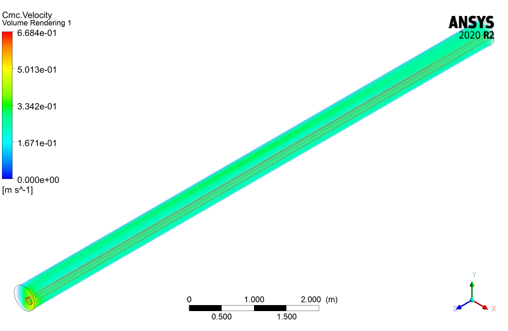
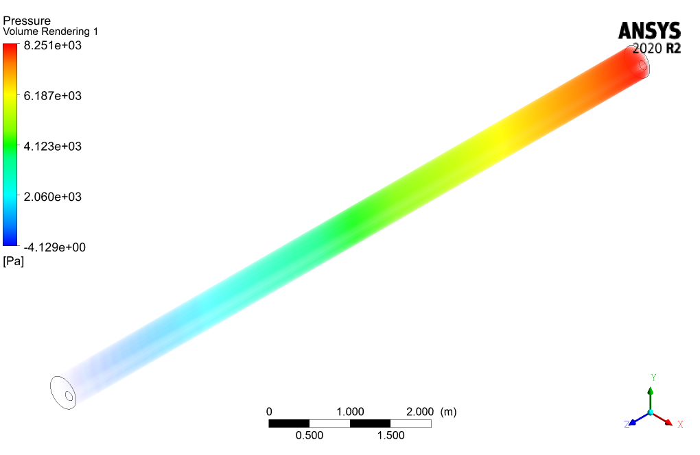
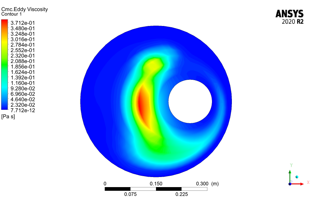
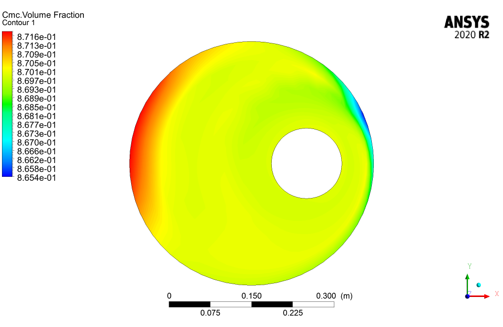
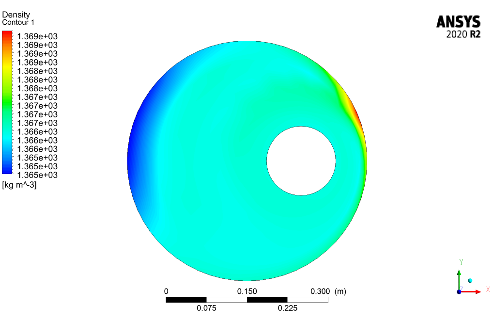
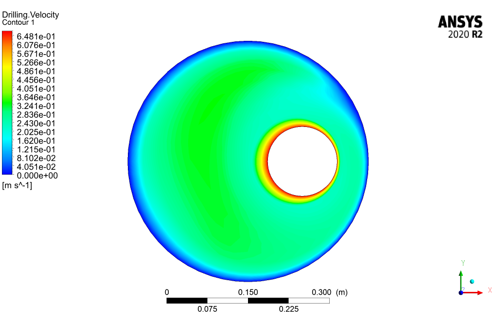
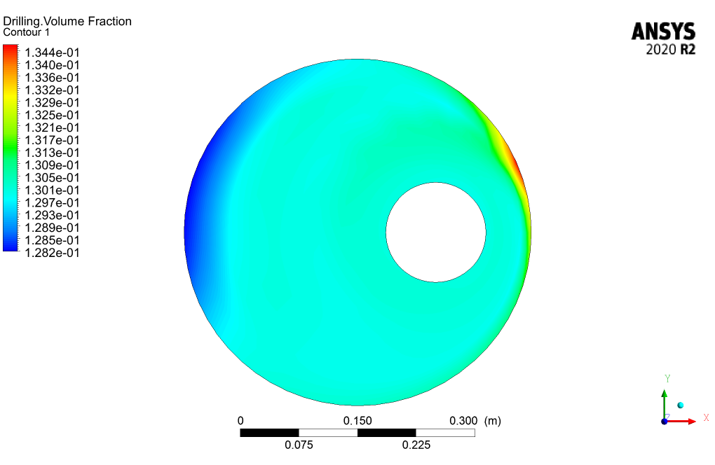
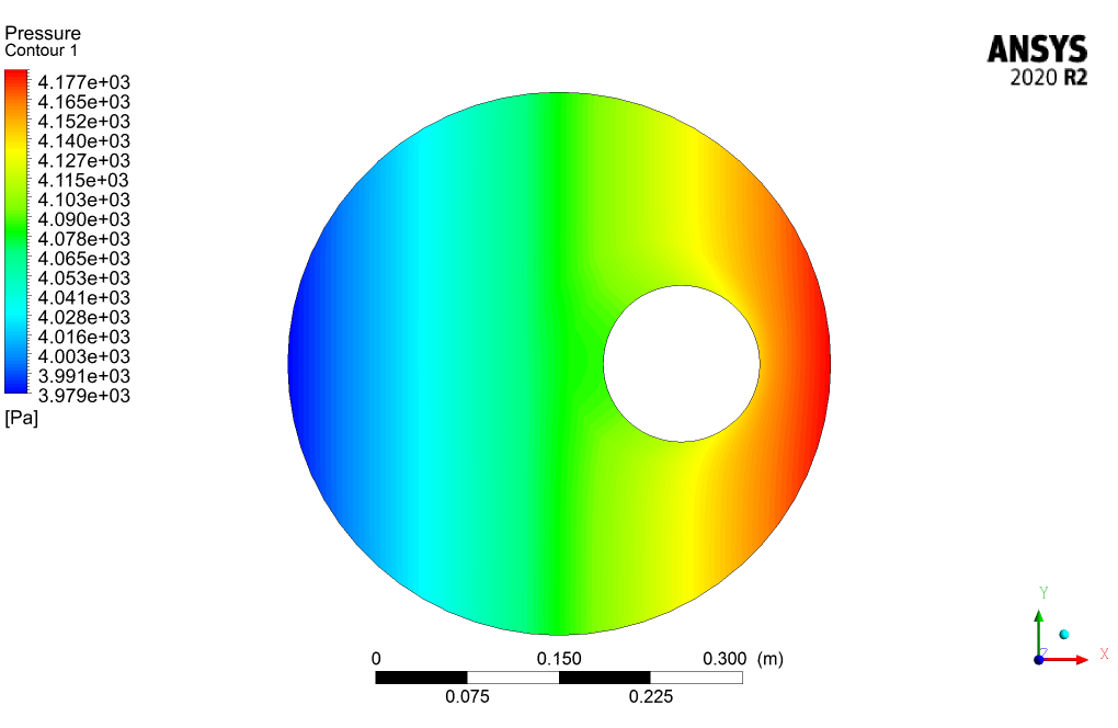
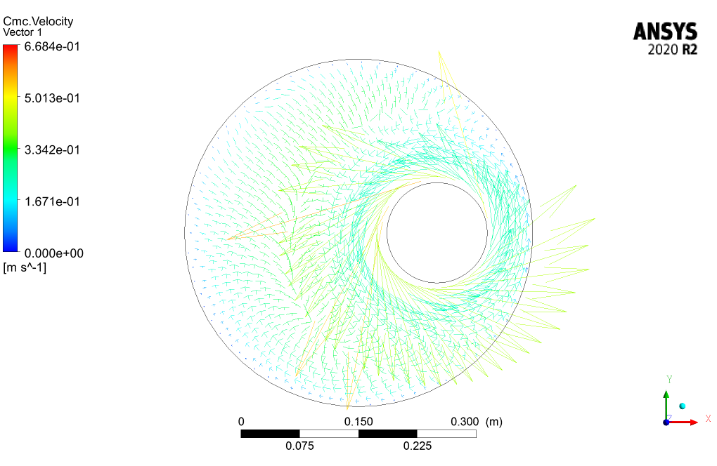
The 3D and 2D contours of pressure, velocity, streamlines, volume fraction, and eddy viscosity are presented. From the results, we can conclude that the drilling volume fraction is maximum in the zones where the CMC volume fraction is the minimum and vice versa.

Mrs. Ada Waters V –
I’ve just finished reviewing the simulation project on non-Newtonian fluid flow between two moving eccentric cylinders and found it fascinating. The methodology to capture the unique properties of the non-Newtonian fluids was well-implemented. Seeing the interaction between the drilling material and CMC presented via both 3D and 2D contours was insightful. It helped me grasp how the drilling phase and the CMC phase occupy the space between the cylinders differently. The flow visualization through streamlines and the detailing of eddy viscosity distribution were highlights for me.
MR CFD Support –
We greatly appreciate your positive feedback and are thrilled to hear that you found the project engaging and the visualization methods helpful in understanding the complex flow of non-Newtonian fluids. Thank you for recognizing our efforts, and if you need further assistance or more information on our simulations and training, feel free to reach out.
Genevieve Smith –
I had fun experimenting with the non-Newtonian fluid project in ANSYS Fluent! The behavior of the fluids between the eccentric cylinders was fascinating.
MR CFD Support –
Thank you for your positive feedback! We’re thrilled to hear you enjoyed working on the non-Newtonian fluid flow project and found the simulation results fascinating. It’s great when our customers can see the dynamic behaviors of such complex fluids through simulations. If you have any other experiences you’d like to share or need assistance with future projects, feel free to reach out to us!
Clemmie Hamill –
The training product perfectly explained the behavior of non-Newtonian fluids in the presence of eccentric cylinders. I’m impressed with how the different viscosities of the fluids were handled and the detailed explanation of the results. Furthermore, the use of structured mesh and the incorporation of the standard k-omega model with low-Re corrections provided deep insights into the flow characteristics. Well done!
MR CFD Support –
Thank you for your positive feedback! We’re delighted to hear that you found the explanation of non-Newtonian fluid behavior comprehensive and the simulation details to be thorough and insightful. Our goal is always to provide clear and detailed training materials, and it’s gratifying to know that we’ve succeeded. We look forward to delivering more high-quality CFD simulations and educational content in the future!
Franco Halvorson –
I just finished my project using your training material on ‘Non-Newtonian Fluid Flow Between Two Moving Eccentric Cylinders,’ and the results were extremely helpful. The contours of pressure and velocity helped me understand how the non-Newtonian fluids behave in these conditions. I didn’t think I would get such accurate results! Amazing work on creating such a detailed simulation.
MR CFD Support –
Thank you so much for your positive feedback! We’re thrilled to hear that our simulation training materials were helpful for your project and that the results exceeded your expectations. Understanding non-Newtonian fluid behavior can be challenging, and we’re glad our detailed simulation could provide the insights you needed. If you have any more questions or need further assistance with future projects, don’t hesitate to reach out. Good luck with your research!
Trisha Morar –
The simulation project seems fascinating and thorough. Could you please provide more insight into how the interaction between the two non-Newtonian fluids is modeled in ANSYS Fluent?
MR CFD Support –
The interaction between the two non-Newtonian fluids is modeled using the Eulerian multiphase model in ANSYS Fluent. This approach allows for the simulation of multiple interacting continuous fluid phases, capturing the phase interactions of the non-Newtonian fluid mixture of Drilling and CMC within the space between the moving eccentric cylinders.
Dr. Chad Glover Jr. –
I just wanted to drop a note saying how fascinated I was with the simulation of non-Newtonian fluid dynamics in this concept. The visual results were incredibly intriguing, showing the interactions between the phases and how they’re affected by the movement of the cylinders. Stellar work on such a complex topic!
MR CFD Support –
Thank you for your kind words! We’re thrilled to hear that you found the non-Newtonian fluid simulation informative and visually compelling. It’s a complex subject, and we strive to deliver clear and detailed insights with our simulations. Your feedback is greatly appreciated and motivates us to keep providing high-quality CFD training materials.
Mrs. Ayla Wyman –
What kind of results does the simulation provide about the behavior of the non-Newtonian fluid in the presence of the moving eccentric cylinders and why is this useful?
MR CFD Support –
The results include 3D and 2D contours of pressure, velocity, streamlines, volume fraction, and eddy viscosity, which demonstrate how the non-Newtonian fluid behaves with the moving eccentric cylinders. Understanding this helps us design better industrial machinery and tools that deal with such fluids, ensuring efficiency and safety in processes such as drilling where non-Newtonian fluids like drilling mud are common.
Haylie Altenwerth –
The training mentions the use of low-Re correction in the k-omega model. Can you explain the benefits of this correction for simulating non-Newtonian flows between cylinders?
MR CFD Support –
Certainly, the low Reynolds number (low-Re) corrections enhance the performance of the k-omega turbulence model by enabling it to more accurately capture the flow characteristics near the wall regions where the flow behavior can be significantly affected by viscosity. In the case of non-Newtonian fluids, whose viscosity varies with shear rate, it is critical to resolve these near-wall flow features due to their sensitivity to changes in viscosity. The low-Re corrections help in predicting the flow separation and reattachment points more precisely, which is essential when dealing with complex, shear-dependent flows like those of non-Newtonian fluids between moving, eccentric cylinders.
Prof. Walter Ward IV –
This simulation seems quite complex. How accurately can ANSYS Fluent capture the behavior of non-Newtonian fluids in such applications?
MR CFD Support –
ANSYS Fluent is equipped with advanced models that allow for accurate simulations of non-Newtonian fluid dynamics. By utilizing the correct constitutive equations and turbulence models, along with proper meshing and time-stepping, ANSYS Fluent can effectively capture the behavior of non-Newtonian fluids, even in complex scenarios like the flow between moving eccentric cylinders.
Roberto Bernhard –
I’m captivated by the project’s findings! Could you explain if the rotational velocity of the internal cylinder affects the volume fraction distribution of Drilling and CMC?
MR CFD Support –
The rotational velocity of the internal cylinder indeed influences the distribution of volume fractions in the flow domain due to the induced shear forces. As the inner cylinder moves, it alters the flow structures, creating zones of different shear rates which affect the viscosity and therefore the dispersion and mixing of the non-Newtonian fluid components.
Dr. Noelia Rau III –
The review is very complimentary and informative, thank you!
MR CFD Support –
Thank you for your positive feedback! We’re glad you found the project on non-Newtonian fluid flow between two moving eccentric cylinders informative. It’s always great to hear that our simulation trainings are appreciated and valuable to our customers. If you have any more insights or questions about our products or need further assistance, don’t hesitate to reach out!
Erika Bashirian –
What kind of mesh refinement was used in this simulation near the walls of the cylinders to capture the flow characteristics of the non-Newtonian fluid accurately?
MR CFD Support –
The simulation utilized structured meshing with low-Re correction to capture the flow near the walls accurately. This approach helps provide more precise results for the complex behaviors of non-Newtonian fluids interacting between the moving eccentric cylinders.
Carole Considine –
I’m really intrigued by how non-Newtonian fluids behave differently from Newtonian fluids you described. Could the methodology and conclusion sections provide additional insights into how the viscosity of the drilling and CMC solution changes during the simulation and its impact on the flow patterns between the cylinders?
MR CFD Support –
Certainly! In this simulation, the viscosity of the non-Newtonian drilling and CMC fluids changes depending on the shear rate they experience between the eccentric cylinders. This varying viscosity affects the flow patterns and induces unique fluid behaviors that differ, particularly, from Newtonian fluids. Utilizing the standard k-omega turbulence model with low-Re correction allows the simulation to accurately capture these effects on flow. Hence, the variations in viscosity are critical to understanding the resultant pressure and velocity fields, as well as the interface between the drilling and CMC fluids as visualized through volume fraction and eddy viscosity contours. All these impact factors are meticulously explored during the CFD analysis to assess the complex interactions within the non-Newtonian fluid flow.
Reanna Becker PhD –
Are there any considerations for the initial conditions in the simulation of the eccentric cylinder problem, since we’re dealing with a non-Newtonian fluid?
MR CFD Support –
In the simulation, initial conditions must be carefully chosen to ensure a stable and accurate solution due to the complex behavior of non-Newtonian fluids. The initial conditions usually include specifying initial values for velocity, pressure, volume fractions of the phases, and possibly other relevant non-Newtonian properties based on the fluid’s rheology model.
Melody Reilly PhD –
I was particularly impressed by the application of non-Newtonian fluid dynamics within the eccentric cylinders model. It’s remarkable to see how the simulation captures the unique behavior of the fluid’s viscosity changes.
MR CFD Support –
Thank you for your positive feedback! We’re delighted to know that you found the simulation of non-Newtonian fluid flow fascinating and insightful. It’s our goal to provide high-quality learning materials that help in understanding complex fluid behaviors accurately. If you ever have more questions or need further information about our simulations or training materials, feel free to reach out.
Yadira Cole –
The simulations are highly enlightening. Could I also customize the materials to simulate different non-Newtonian fluids apart from Drilling and CMC?
MR CFD Support –
Thank you for your positive feedback! Yes, you can customize the materials in ANSYS Fluent to simulate a wide range of non-Newtonian fluids. The software allows you to define your own fluid properties, including viscosity models that accommodate thixotropic, dilatant, or viscoelastic behaviors tailored to your specific fluid’s characteristics.
Lukas Hamill –
The explanation about the non-Newtonian fluid behavior was insightful! I could visualize exactly how the viscosity changes when the substance is under stress, much like ketchup or honey. The information about simulating the flow between two moving eccentric cylinders using ANSYS Fluent piqued my interest, especially the usage of the low-Re correction in the k-omega model to improve accuracy. In educational materials like these, it’s essential to understand both the theoretical concepts and the practical simulation methods – and it seems like this training content has nailed it!
MR CFD Support –
We’re pleased to hear that you found the simulation of non-Newtonian fluid flow between moving eccentric cylinders insightful and that the provided details helped in your understanding of both the theory and application in ANSYS Fluent. Thank you for sharing your positive experience with our learning material!
Prof. Reyes Rodriguez I –
The training clearly explained the simulation process for the non-Newtonian fluid, but could you clarify which properties of the drilling and CMC solutions were considered in setting up the simulation? Were specific viscosities or any rheological properties predefined?
MR CFD Support –
In the setup of the simulation for non-Newtonian fluids, specific viscosities and rheological properties pertinent to the drilling and CMC solutions were indeed predefined. These properties would include viscosity curves showing how the viscosity changes under differing shear rates. The model would then use these curves to accurately simulate the behavior of the fluids under force within the boundary conditions established.
Sofia Welch –
The tutorial really gave me a solid understanding of non-Newtonian fluids and the dynamics involved in a complex flow system like the one with eccentric cylinders. The visualizations and detailed analysis helped me grasp some intricate concepts!
MR CFD Support –
Thank you so much for your positive feedback! We’re thrilled to hear that our tutorial was helpful and that the complex concepts were made clear through our visualizations and explanations. If there’s anything else we can assist with or if you are interested in exploring more topics, please let us know!
Mr. Talon Medhurst –
I’m really intrigued by how the software handles the differing viscosities in the drill and CMC non-Newtonian fluids. Can you explain how ANSYS Fluent manages this during the simulation?
MR CFD Support –
In ANSYS Fluent for the simulation of non-Newtonian fluids, the software allows for defining the viscosity models that best approximate the fluid behavior. Depending on the characteristics of the non-Newtonian fluid, users can choose from several viscosity models like Power-law, Herschel-Bulkley, or Casson. These models take into account the variations in viscosity under different shear rates. The software then incorporates these viscosity models into the flow equations and iteratively solves them, allowing the viscosity to adjust in response to the flow conditions and applied forces.
Norma Pollich –
I’m quite fascinated by the project’s approach to the flow of non-Newtonian fluids between concentric cylinders. I noticed that the Eulerian multiphase model is mentioned. Could you please elaborate on how this specific flow was set up within ANSYS Fluent for this model?
MR CFD Support –
In this simulation, the Eulerian multiphase model accommodates the interactions of two distinctly different phases of non-Newtonian fluids. The model allows for each phase to possess its own material properties and flow patterns. The fluids enter the spacing between the two eccentric cylinders with defined initial velocity. As one cylinder rotates, the impact on the fluid dynamics and the phase distribution is accurately captured due to the low Re correction and the k-omega turbulence model, resulting in detailed profiles of various relevant quantities like pressure, velocity, and volume fraction distributions.
Dr. Dagmar Kessler IV –
The review is impressive! It sounds thorough and the simulation comprehensive, explaining the dynamic relationship between non-Newtonian fluid properties and moving parts. Does the simulation also analyze the effects of varying the rotation speeds of the inner cylinder on the fluid flow patterns, or was it kept constant throughout the study?
MR CFD Support –
Thank you for your interest in our non-Newtonian fluid flow simulation between two eccentric cylinders. In this particular project, we set a constant rotation velocity for the inner cylinder to establish a consistent basis for analyzing fluid flow behavior. Nonetheless, the effect of different rotation speeds on the flow patterns represents an interesting variable. While out of scope for this simulation, this is certainly an additional study that could be carried out through subsequent simulations if there’s a need for exploring those effects in more detail.
Theron Johnston –
I was wondering if there is a recommended range of rotation speeds for the inner cylinder to fully observe the non-Newtonian behavior in the simulation?
MR CFD Support –
In the simulation of non-Newtonian fluid flow between two moving eccentric cylinders, the rotation speed of the inner cylinder can significantly impact the results. It is generally recommended to vary the rotation speed within a range that is representative of real-world applications where such fluid dynamics are encountered. A starting point would be to research typical operation conditions of relevant machinery or processes. An initial speed can be set based on the natural frequency of the fluid and the cylinder, and then several simulations can be run incrementally increasing the speed to observe changes in the fluid’s behavior. The actual speed range may depend on various factors, including the type of non-Newtonian fluid being simulated and the specific objectives of the simulation. However, it is best to consult with fluid dynamics experts or refer to industry standards to determine the most appropriate range for your simulation.
Paige Weimann –
The training helped me understand non-Newtonian fluids much better! I was delighted to see how the eccentric cylinders influence the flow patterns. Great CFD simulation!
MR CFD Support –
Thank you for your positive feedback! We’re glad to hear that our CFD simulation training on Non-Newtonian Fluid Flow Between Two Moving Eccentric Cylinders helped enhance your understanding of the subject. If you have further interest in exploring similar simulations or have any questions, feel free to reach out to us. We always strive to assist our learners in expanding their knowledge.
Bethany Ankunding –
I found the work done on the non-Newtonian fluid dynamics between moving eccentric cylinders absolutely fascinating! Could you share with me what the specific applications for this type of simulation might be in real-world scenarios?
MR CFD Support –
Thank you for your kind words! Such simulations are crucial in industries where handling non-Newtonian fluids is common, including the food, cosmetical, pharmaceutical, and oil industries for applications involving mixing, transport, and processing of materials with complex flow behaviors. Simulating these interactions helps in designing efficient equipment and processes.
Ms. Ruby Boyle –
I’m truly fascinated by the simulation of non-Newtonian fluids! Can the model handle sudden changes in viscosity or is it more suited for gradual transitions?
MR CFD Support –
The model in ANSYS Fluent is capable of handling both sudden and gradual changes in viscosity since it uses a non-Newtonian fluid model. The software can adjust viscosity based on the applied stress or strain rate, ensuring accurate simulation of non-Newtonian fluid behavior under various conditions.
Prof. Aaliyah Goldner –
Can you explain how the moving wall condition on the inner cylinder affects the non-Newtonian fluid flow in the simulation?
MR CFD Support –
In the simulation, when we apply a moving wall condition to the inner cylinder, it causes the fluid in contact with the cylinder to be dragged along due to the no-slip condition at the boundary. This results in a rotational flow pattern around the inner cylinder. Given that the fluid is non-Newtonian, this movement can alter its viscosity depending on the shear rate induced by the rotating cylinder. The change in viscosity will influence the flow behavior, resulting in complex and varying flowing conditions between the two eccentric cylinders.
Dariana Aufderhar –
I am impressed by the detailed simulation of non-Newtonian fluid flow between eccentric cylinders. How accurately does the simulation represent real-life fluid behaviors in industrial applications?
MR CFD Support –
Thank you for your positive feedback! The simulation is designed to closely represent real-life non-Newtonian fluid behaviors by incorporating the non-Newtonian fluid properties and the interaction dynamics between the moving cylinders. Advanced numerical methods and models, such as the Eulerian multiphase model and the k-omega turbulence model with low-Re corrections, enhance the accuracy. This enables the simulation to account for complex fluid behaviors often encountered in industrial applications like drilling, making sure that outcomes like pressure distribution, velocity profiles, volume fraction, and turbulence are depicted realistically.
Rebeka Spinka –
I’m thoroughly impressed with the level of detail presented in the Non-Newtonian Fluid Flow CFD Simulation Training. The dynamic interactions captured between the two phases of Drilling and CMC in the eccentric cylinders were particularly intriguing. Is this type of analysis applicable to other non-Newtonian fluids in different industrial applications?
MR CFD Support –
Absolutely! This type of CFD analysis can indeed be applied to various non-Newtonian fluids across different industries. The methodology for handling the fluid dynamics will be analogous, allowing for insights into the behavior of such fluids under different conditions in real-world applications. The flexibility in adjusting simulation parameters makes it highly beneficial for industries that deal with non-Newtonian fluids.
Pascale Harber –
I found the way that the mixture of Drilling and CMC was handled fascinating. Could you provide more details on how the flow of the non-Newtonian fluid was specifically modeled and calculated in this project?
MR CFD Support –
Horizon-area modeling was used for the detailed simulation of the non-Newtonian fluid characteristics based on viscosity being a function of shear rate. The software dynamically adjusts the viscosity during the simulation in response to the changing stress states due to the rotating inner cylinder and the velocity of the non-Newtonian mixture.