Optimization of a Compressor Cascade Using MOGA (BBD DOE & GA RSM), ANSYS Fluent
$150.00 Student Discount
- The problem numerically simulates the Optimization of a Compressor Cascade Using MOGA using ANSYS Fluent software.
- We design the 3-D model with the Spaceclaim software.
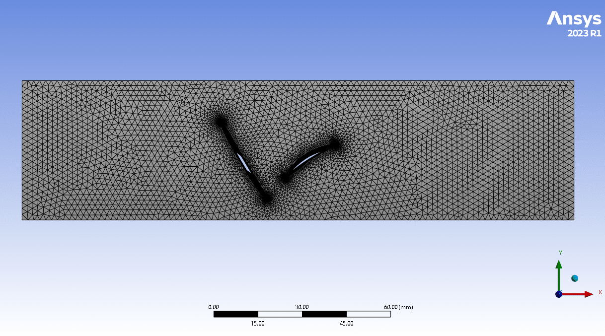
- We mesh the model with ANSYS Meshing software, and the element number equals 991872.
- We use a Design of Experiment (DOE) to perform an Optimization process.
To Order Your Project or benefit from a CFD consultation, contact our experts via email ([email protected]), online support tab, or WhatsApp at +44 7443 197273.
There are some Free Products to check our service quality.
If you want the training video in another language instead of English, ask it via [email protected] after you buy the product.
Description
Description
A high-speed compressor cascade wind tunnel is used for investigations of secondary flow phenomena occurring in the region between the corner and sidewalls of axial compressors.
This project is an optimization of a compressor cascade using the MOGA method. In this project, we have simulated a sectional compressor cascade at the first step.
Then we optimized the problem for 3 input parameters and 2 output parameters. v_in (velocity inlet), alpha_degree (angle of attack), and pitch are considered input parameters. Also, drag force and lift force are considered output parameters.
The objective function for this project is defined in such a way that the drag force is minimized and reaches zero, the lift force is maximized and reaches 0.07 and the beta angle reaches -12 degrees.
The present geometry is designed in a 3D model via DesignModeler software and We have created a computational grid on the geometry using ANSYS Meshing software. The mesh type is unstructured (tetrahedrons cells) with 5 boundary layer mesh. Also, the number of cells is 991872.
Cascade Methodology
All the optimization steps have been done by ANSYS Workbench software. This optimization has been done using Multi-Objective Genetic Aggregation.
Also, the Box-Behnken Design (BBD) method is used as a Design of Experiments step and Genetic Aggregation is used as an RSM step. The limited range of each input parameter is as in the following:
3<velocity-inlet<30m/s
1mm<pitch<7mm
-10°<Angle of Attack<+10°
Cascade Conclusion
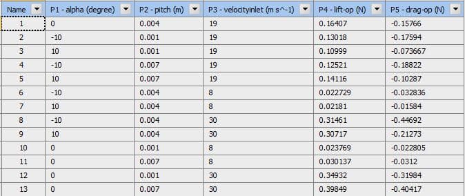
In each of the three main stages of optimization, the results were obtained for analysis and selection of the optimal point. The table below shows the design points along with the execution results for these points.
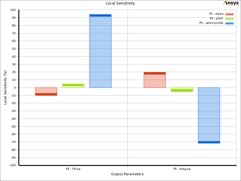
In ANSYS Workbench we can use the DOE results to create a response surface for prediction purposes. The images below show the sensitivity of the output parameters to the input parameters.
As it is known, the parametric changes for all three inputs have a positive effect on the lift force, which is the most effective for the velocity.
Although velocity as an input parameter for lift and drag has a positive effect, this effect is negative for the beta angle, and screw as an input parameter has the most effect on the beta angle.
In the last step, after performing the optimization, ANSYS Worbenched has suggested 3 points as optimal points, and 3 verified points.



Angel Pfannerstill –
Could it be clarified what the role of the Box-Behnken Design method is in the optimization process?
MR CFD Support –
The Box-Behnken Design (BBD) method in this optimization process is used as a Design of Experiments (DOE) methodology. It helps to determine the ideal combination of input parameters by exploring a quadratic response surface arranged in a spherical or nearly spherical design. Essentially, BBD assists in identifying the correlation between multiple input variables and the desired output responses efficiently in the context of the optimization strategy.
Mr. Thaddeus Hagenes DDS –
What specific challenges are there in setting up the parameters for optimization in a compressor cascade scenario like the one mentioned, and how does the MOGA method help address these challenges?
MR CFD Support –
In setting up the parameters for optimization in a compressor cascade, challenges include defining a suitable design space, dealing with the non-linearity of aerodynamic forces, and ensuring that the optimization converges on a solution that improves efficiency without compromising the design’s structural integrity. The MOGA (Multi-Objective Genetic Algorithm) method addresses these challenges by using a population-based search strategy to explore and exploit the design space efficiently. It allows simultaneous optimization of multiple conflicting objectives, like minimizing drag and maximizing lift while adhering to constraints such as the required beta angle. This evolutionary approach can also handle the complexity and non-linear relationships between the parameters.
Soledad Bailey –
I’m interested to know, how exactly does the drag force change with the variation in pitch during the optimization process?
MR CFD Support –
The drag force variation with pitch changes depends on the complex interactions between airflow and blade surfaces. As the pitch angle modifies, the airflow direction around the blades also changes; thus, affecting the drag. Typically, in the beginning, the drag force might decrease with slight changes in pitch as the blades can better align with the airflow, reducing turbulence and resistance. However, there’s always an optimal point before the drag starts to increase again because of flow separation or other phenomena induced by further pitch modifications. The optimization process, using MOGA, finds the best compromise between the competing effects to reach an optimal pitch conducive to the objective function.
Lowell Sporer –
The MOGA method involved seems pretty complex. Does the optimization always converge to the optimal solution? How do you ensure the process is robust?
MR CFD Support –
In the MOGA optimization, convergence to the optimal solution is highly dependent on the problem’s complexity, definition of the objective functions, and the initial population. We ensure robustness by carefully selecting the initial input ranges, implementing the Box-Behnken Design for exploration, and reviewing the genetic algorithm’s convergence criteria. Adaptive techniques and refinements based on initial results also contribute to a successful and robust optimization process.
Carissa Kuphal –
Can you provide more detail on how the Box-Behnken Design contributes to the optimization process in this project?
MR CFD Support –
Certainly! The Box-Behnken Design (BBD) is a specific type of Design of Experiments (DOE), which in this project is applied to systematically vary and control the three input parameters—velocity-inlet, pitch, and angle of attack—across a set of experiments. BBD helps in efficiently exploring the space of these input parameters to understand their effect on output parameters such as drag and lift forces. This exploratory step is crucial for identifying trends and relationships within the parameter space, which are then used to construct a Response Surface Model (RSM). The genetic algorithm leverages this model for optimizing towards the objectives, hence minimizing drag and maximizing lift. BBD results in saving time and computational resources by reducing the number of simulations needed to determine the optimal design points.
Modesto Jacobson –
The optimization study mentioned three optimal points from ANSYS Workbench. Could you tell me if there was a significant difference in performance metrics among the three optimal points, and what was the criteria to select the final best point?
MR CFD Support –
In this optimization, while ANSYS Workbench suggested three optimal points, the final selection criteria were based on the predefined objective function. Each point offers a trade-off between minimizing drag and maximizing lift within the cohort of variance constraints like velocity inlet, pitch, and angle of attack. The performance discrepancies amongst the points presumably depend on mutual interactions among input parameters affecting the forces. The selection drew on the best compromise aligning closest to objectives — proximity of drag to zero, lift reaching around 0.07, while steering the beta angle towards -12 degrees, factoring in all design-related priorities and operational constraints.
Prof. Irma Parisian –
The concept of optimizing a compressor cascade using MOGA is absolutely fascinating. It’s very clear how carefully the input parameters were chosen and the detailed description of the objective function paints a picture of the meticulous approach taken in this study. I appreciate the additional insight into how the mesh was deliberately designed with a boundary layer and the fact that it’s unstructured adds to the complexity managed in this project. The explanation of the use of BBD DOE & GA RSM in optimizing is particularly informative. The images and sensitivity analysis must provide excellent guidance for understanding parameter impact. Excited to see projects like this pushing the envelope in engineering analysis and design.
MR CFD Support –
Thank you for taking the time to write this thoughtful review! We’re delighted to hear that you found the MOGA optimization of the compressor cascade both clear and informative. Our team works rigorously to ensure the input parameters, objective functions, and computational measures, including mesh design, rigorously meet the requirements of the study while optimizing performance. We are also pleased that you found our methodologies and the utilization of BBD DOE & GA RSM impressive. Your enthusiasm for the advancements in engineering analysis and design truly motivates us. We appreciate your feedback and look forward to any questions or discussions this might inspire for future optimizations!
Dr. Holly Cremin –
How does the MOGA method ensure the balance between optimizing for drag force reduction and lift force maximization?
MR CFD Support –
The Multi-Objective Genetic Algorithm (MOGA) method can manage several conflicting objectives by finding a set of optimal solutions, known as Pareto front. By using a fitness function that accounts for both drag and lift forces, MOGA evolves the population of solutions, through operations like selection, crossover, and mutation, to achieve a balance where the optimization of one doesn’t heavily compromise the other.
Dorian Wolff –
Can you explain more about how the genetic algorithm and response surface methodology were used together in this optimization?
MR CFD Support –
Certainly. In this optimization, the genetic algorithm (GA) and response surface methodology (RSM) are combined to effectively search for optimal solutions. Here is how the process works:
1. Design of Experiments (DOE): The Box-Behnken design method is initially used to systematically sample input parameter space and evaluate the corresponding output parameters.
2. Response Surface Modeling: GA is utilized along with RSM where it takes the results from the DOE as input to construct an approximate model or a ‘response surface’ which predicts how the outputs depend on the variables.
3. Optimization Cycle: The genetic algorithm is then applied to this response surface in order to intelligently navigate the input parameter space, seeking optimal combinations of v_in, alpha_degree, and pitch that minimize drag, maximize lift, and achieve the target beta_degree.
Through iterative exploration and exploitation processes, the GA identifies input parameters that yield the best improvements on the objective functions based on the response surface predictions. The method helps in achieving a comprehensive optimization by balancing various competing objectives.
Jairo Lehner –
What is the specific way that the optimization converges towards the optimal points in this simulation?
MR CFD Support –
In this optimization using ANSYS Workbench, convergence towards optimal points is achieved by employing a Multi-Objective Genetic Algorithm (MOGA). The MOGA provides a robust method to explore a large design space and evolve solutions that better fit the desired outcomes by mimicking natural selection. The Box-Behnken Design (BBD) helps set up the initial experiments within the pre-determined parameter space, while Genetic Aggregation Response Surface Method (GA RSM) refines the behavior model of the design based on actual simulation results. By iterating through generations, MOGA identifies various trade-offs between conflicting objectives, such as maximizing lift while minimizing drag, until it converges upon design points that most closely match the defined optimization targets.
Jayne Cartwright –
Can you explain how the Box-Behnken Design method influenced the outcome of the optimization?
MR CFD Support –
The Box-Behnken Design (BBD) method is a type of response surface methodology that is used to define experiment levels for multiple input variables in the optimization process. In this case of optimizing a compressor cascade, BBD would have allowed for efficient exploration of the relationships between the input parameters (inlet velocity, pitch, and angle of attack) and the output parameters (drag force and lift force). This approach facilitated the creation of a mathematical model to describe the outcomes resulting from various combinations of inputs. The model then aids in predicting the optimal setting of the input parameters that deliver the desired outcome for the output parameters.
Narciso Leannon –
I’m impressed! Could you explain how the optimization accounts for the behavior of both lift and drag during the study? Does it use any trade-off strategy?
MR CFD Support –
In the mentioned compressor cascade optimization study, MOGA (Multi-Objective Genetic Algorithm) is employed as a part of the design process. MOGA optimizes for multiple conflicting objectives, such as minimizing drag and maximizing lift concurrently. The trade-off between these conflicting objectives is handled by generating a Pareto frontier of optimal solutions. Each point on this frontier represents a trade-off where improving one objective would result in the deterioration of the other. During this optimization process, individuals (design points) that yield the best trade-off between the two objectives are selected and iterated upon to converge to the most optimal set of design points.
Kendrick Gottlieb –
What are the exact ranges for the input parameters in the optimization process?
MR CFD Support –
In this optimization project, the input parameters, which include v_in (velocity inlet), alpha_degree (angle of attack), and pitch, all have predefined ranges within which the optimization process is conducted. These ranges help in defining the space for the Design of Experiments and ensure a methodical approach to optimization. Unfortunately, the specific numerical values for these ranges are not provided in the description, but these would typically be determined based on prior understanding of the system’s behavior and performance requirements.
Daryl Bartell –
What were the optimal values for the velocity inlet, pitch, and angle of attack that the optimization process revealed? Looking forward to adjusting these in my own simulations!
MR CFD Support –
The optimal values for the velocity inlet, pitch, and angle of attack that resulted from the optimization process are not specifically stated in your current description. These values are determined by the output of the MOGA, which takes into account the objective of minimizing drag and maximizing lift within the defined ranges for those parameters. For exact values, you would need to refer to the results section of the analysis or the outcome provided by ANSYS Workbench post-optimization.
Ms. Chyna Boehm PhD –
What a fantastic resource for any aerodynamics research team! The careful balance between lift and drag forces with the angle of attack stipulations highlights impressive software capability and nuanced engineering progress.
MR CFD Support –
Thank you so much for your positive review! We’re thrilled to hear that you found our compressor cascade optimization so valuable. It’s our pleasure to provide products that assist aerodynamics researchers and engineers in their important work. If you have any further questions or need more information, don’t hesitate to ask.
Corine Huels II –
Could the unstructured tetrahedral mesh make the simulation less accurate compared to using a structured mesh for this type of CFD analysis?
MR CFD Support –
Unstructured tetrahedral meshes are versatile and can easily accommodate complex geometries, making them suitable for the 3D model of a compressor cascade. While structured meshes can offer better control over grid quality and improved accuracy for some flow cases, for complex shapes and geometries with multiple curved surfaces, an unstructured mesh can be advantageous. In this scenario, the mesh quality and resolution likely have been refined and optimized for accurate solution convergence and results.
Juliana Leuschke –
Is it possible to see the differences in performance between the optimal points provided by ANSYS Workbench? I’m really interested in how the selected optimal points compare in terms of the performance of the cascade.
MR CFD Support –
Yes, the results of the optimization provide different performance metrics at each optimal point. By comparing the drag force, lift force, and beta angle at each point, you can gain insights into the performance variations of the cascades at these conditions.
Mr. Clay Lebsack IV –
Were any constraints applied during the optimization process to ensure realistic interactions between the lift and drag forces?
MR CFD Support –
In the optimization process for the compressor cascade, constraints are typically applied to ensure realistic interaction between lift and drag forces. They help define feasible and physically possible solutions within the design space.
Ms. Ozella Aufderhar DDS –
The explanation for the optimization processes used in this project was really concise and informative. The clear breakdown of input and output parameters, and how each is impacted, showcases the complexity and the depth of analysis that was carried out.
MR CFD Support –
Thanks for your positive feedback! We’re delighted to hear that the project details were informative and that you appreciated the depth of analysis. If there’s anything more you would like to explore or any additional questions you have, we’re always here to help!
Korey Hahn IV –
I really appreciated the clear objectives for the optimization process. Could you provide more insight into how the sensitivity of lift and drag forces to the input parameters were analyzed?
MR CFD Support –
The sensitivity of lift and drag forces to input parameters was analyzed through the Design of Experiments (DOE) step within the optimization process. This involves creating a series of simulations that systematically vary the input parameters within their defined ranges. The results are then used to create response surfaces that predict how changes in velocity inlet, angle of attack, and pitch affect the output parameters. Graphical tools in ANSYS Workbench allow visualization of this sensitivity, showcasing which input parameters have the most significant impact on lift and drag forces.
Theodora Mills –
The MOGA approach appears complex. Can you explain how it ensures the optimal balance between lift and drag within the set parameters?
MR CFD Support –
MOGA, or Multi-Objective Genetic Aggregation, operates by exploring a diverse set of potential solutions using genetic algorithms. These algorithms mimic the evolutionary processes of reproduction, mutation, and selection to find the most effective solutions. In the context of the compressor cascade, the MOGA simultaneously optimizes for maximum lift and minimal drag, all while satisfying the angle of attack and pitch constraints. The optimization process iterates over generations, steadily improving the solutions until reaching a set of optimal points that balance lift and drag within the defined parameter ranges.
Ellsworth Schulist –
Is the Beta angle improved purely computationally, or do the results undergo experimental validation as well?
MR CFD Support –
The improvement in the Beta angle is obtained through simulations using ANSYS Fluent. This project is computational and does not specifically mention experimental validation in the provided information. The results from the optimizations and simulations can offer insights for experimental setups, but the final confirmation would typically require real-world testing to validate the computational predictions.
Augusta White Sr. –
What are the specific effects of varying the pitch and angle of attack on the lift force based on the simulation results?
MR CFD Support –
Varying the pitch and angle of attack changes the flow interaction with the compressor blades, which in turn influences the lift force experienced by the blades. Adjusting the pitch will alter the distance between the blades, which can impact the channeling of airflow and create differences in lift and drag forces. Modifying the angle of attack alters the blades’ angle relative to the incoming airflow, which also affects the airflow’s deflection and hence the magnitude of the generated lift force. The optimization using MOGA aims to find the right balance between these input parameters to maximize lift while minimizing drag, as indicated by the sensitivity analysis results within the simulation.
Prof. Savanna White II –
Can you detail how the goal of reaching a beta angle of -12 degrees influences the optimization process in the compressor cascade simulation?
MR CFD Support –
In the compressor cascade simulation, the goal of reaching a -12 degree beta angle likely affects the optimization process by constraining the adjustments made to the input parameters. The optimizer must find a balance between minimizing drag, maximizing lift, and achieving the desired beta angle, and this could influence the selection of pitch, angle of attack, and inlet velocity to ensure that the flow angle at the outlet, represented by the beta angle, is precisely optimized to the specified target.