Waterfall CFD Simulation Using Two-Phase Flow, ANSYS Fluent Tutorial
$80.00 Student Discount
- The problem numerically simulates the natural Waterfall using ANSYS Fluent software.
- We design and mesh the 3-D model with the Gambit software.
- The mesh type is Structured, and the element number equals 626400.
- We use the VOF Multi-Phase model to define two-phase, including water and air.
To Order Your Project or benefit from a CFD consultation, contact our experts via email ([email protected]), online support tab, or WhatsApp at +44 7443 197273.
There are some Free Products to check our service quality.
If you want the training video in another language instead of English, ask it via [email protected] after you buy the product.
Description
Description
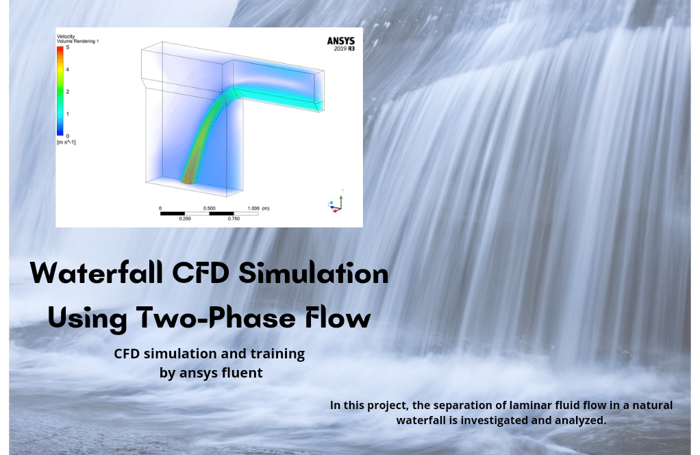
In this project, the separation of laminar fluid flow from a surface easily seen in a natural Waterfall is investigated and analyzed using ANSYS Fluent software. We perform this CFD project and investigate it by CFD analysis.
The geometry and the mesh for this project are created inside Gambit. The geometry includes a mass-flow inlet, 3 pressure outlets, several symmetries and wall boundary conditions and 9 different partitions.
The mesh type used for this geometry is structured, and the element number is 626400.
Waterfall Methodology
Flow separation from a surface or separation of two-phase flows (natural waterfall) is one of the most important issues in fluid mechanics. Flow separation due to the specific shape of the geometry or flow can have positive or negative effects on its surroundings.
Therefore, it has always been tried to control this phenomenon as much as possible and investigate its possible effects and consequences. The VOF multiphase model has been enabled to simulate the two phases of water and air in this project.
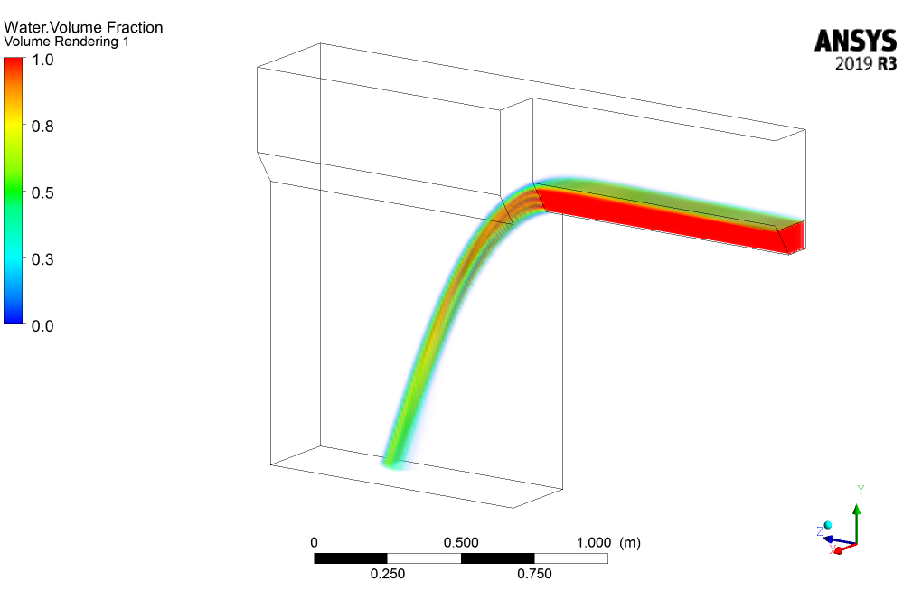
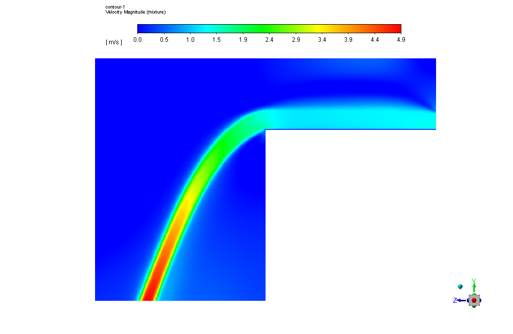
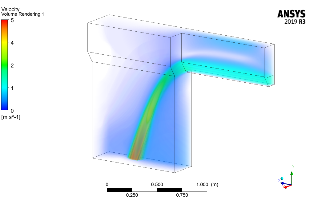
Water enters the domain with a mass flow rate of 20Kg/s and falls due to the model’s geometric shape and gravity’s effect. Also, the RNG k-epsilon model is used to solve turbulent fluid equations.
Waterfall Conclusion
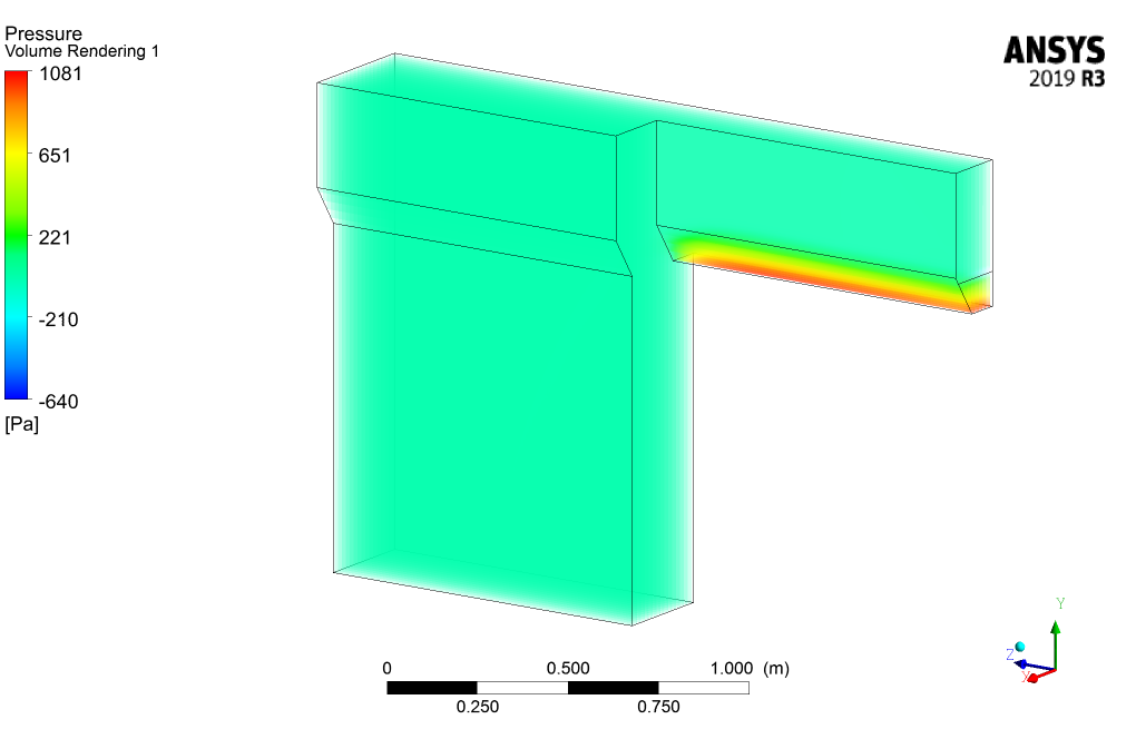
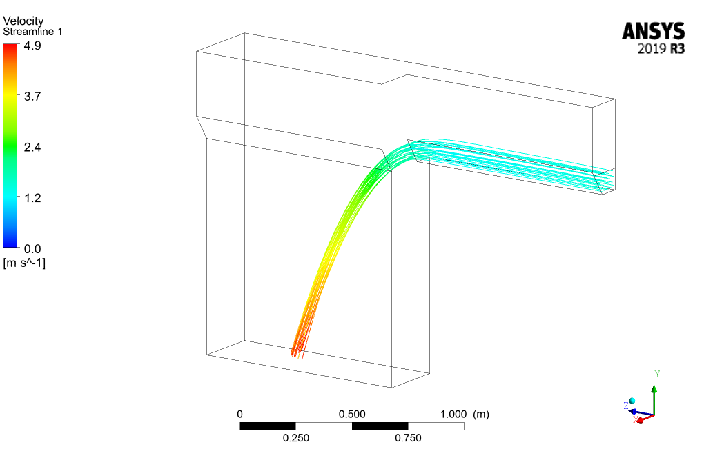
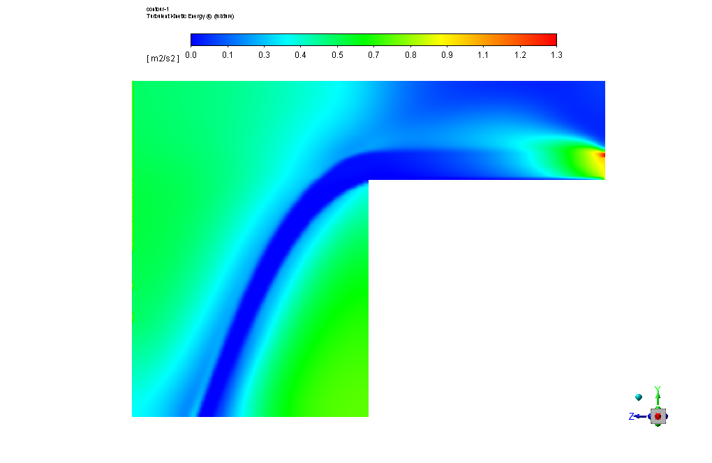
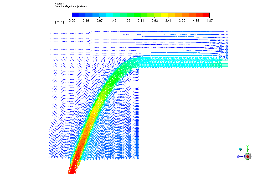
At the end of the solution process, two and three-dimensional contours related to the velocity, pressure, streamlines, and volume fractions inside the domain are obtained. The water volume fraction contour clearly shows how the water flow will behave due to the effect of gravity as it reaches a ledge.
Moreover, if velocity vectors are viewed with care, it can be seen that due to the surface tension that exists between water and air, the water jet produced by the waterfall will cause the airflow to form a subtle flow near the free surface of the water, which its effect can also be seen in the turbulent viscosity contour.

Mr. Gussie Okuneva II –
This tutorial seems incredibly informative! The focus on flow separation in a waterfall scenario reveals key fluid dynamics lessons. The structured mesh’s refinement surely contributes to the accuracy of your simulations, which must be spectacular to witness. Do you provide the final files after completing the tutorial, allowing users to explore the results further?
MR CFD Support –
Thank you very much for your kind words! We’re delighted to hear you recognized the tutorial’s depth. Yes, users who complete the tutorial will indeed have access to the final files. This allows for an immersive learning experience, as you can dive into the results, tweak parameters, and fundamentally understand the simulation process.
Toni Wiegand –
Excellent tutorial! The detailed descriptions and images are very instructive. Following your steps, the very complex phenomenon of a natural waterfall could be captured impressively within the simulated environment. This detailed CFD approach is a must-have for students and researchers interested in environmental and water resources engineering!
MR CFD Support –
Thank you for your flattering feedback on the Waterfall CFD Simulation tutorial using ANSYS Fluent. We’re delighted to hear you found the tutorial details and visual aids instructive and valuable for capturing complex natural phenomena. We are proud to assist students and researchers in their engineering pursuits!
Prof. Giovanny Bosco DDS –
I am very impressed by the results this tutorial provided for such a complex two-phase flow. It allowed for a detailed observation of the water behavior and how airflow is affected due to the spray from the waterfall. Top-quality content indeed!
MR CFD Support –
Thank you for the positive feedback! We are delighted to hear that you found the Waterfall CFD Simulation tutorial helpful and informative. It’s great to know that you were able to gain a detailed understanding of the complex fluid behaviors involved in the waterfall phenomenon. Your appreciation means a lot to us, and we look forward to providing more quality content for your learning needs!
Dr. Anastacio McDermott Sr. –
I’m thrilled to see how you’ve modeled the complex physics of a natural waterfall. I’m curious, what challenges did you encounter while using the VOF model to simulate the interaction between the water and air, and how did these affect the simulation results?
MR CFD Support –
Thank you for your kind feedback! The primary challenges in simulating the waterfall using the VOF model include accurately capturing the interface between the water and air, which requires fine mesh resolution and careful setup of boundary conditions. To achieve realistic results, it is crucial to ensure that the VOF model can reliably track the surface tension and prevent numerical mixing. These challenges were addressed by creating a structured mesh that ensured proper resolution of the free surface and implementing the RNG k-epsilon turbulence model to appropriately capture the turbulent nature of the flow, as well as the subtle flow of air near the water’s free surface. Overcoming these challenges allowed the simulation to produce the detailed and realistic behavior of the waterfall as observed in the resulting contours.
Daron Ward –
Just wanted to compliment the detailed explanation provided for the Waterfall CFD Simulation Using Two-Phase Flow, ANSYS Fluent Tutorial. It really helped me understand the impact of gravity on the water flow and the subsequent air flow caused by the surface tension. The level of detail was particularly useful in appreciating how flow separation is handled in fluid dynamics.
MR CFD Support –
Thank you so much for your kind words! We are thrilled to hear that our Waterfall CFD Simulation tutorial was able to provide you with valuable insights into fluid dynamics and flow separation. If you have any more questions or need further assistance, feel free to reach out. Your satisfaction with our learning products is our top priority.
Mr. Kiel Upton V –
What are the key indicators to watch in the results, that tell me if my waterfall simulation is accurate?
MR CFD Support –
In your waterfall simulation, the key indicators of accuracy would involve closely observing the water volume fraction contour to see if it depicts a realistic waterfall behavior, velocity vectors for the presence of surface tension effects between water and air, and ensuring that the streamlines and turbulent viscosity contours are consistent with expected flow patterns. Verification against experimental data, when available, would also serve as an important accuracy check.