
Particle Transport in Bent Pipe by ANSYS CFX
$100.00 Internship
- In this project, copper Particle Transport in Bent Pipe is investigated using ANSYS CFX software.
- The geometry is designed in a 3D model with the SpaceClaim software.
- We performed the mesh of the model with ANSYS Meshing software, and the element number equals 139,461.
- Particle Transport Fluid Morphology is used to model the motion of copper particles.
To Order Your Project or benefit from a CFD consultation, contact our experts via email (info@mr-cfd.com), online support tab, or WhatsApp at +44 7443 197273.
There are some Free Products to check our service quality.
If you want the training video in another language instead of English, ask it via info@mr-cfd.com after you buy the product.
Description
Particle Transport in Bent Pipe CFD Simulation, ANSYS CFX Tutorial
Description
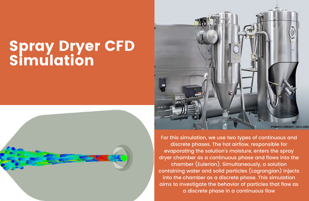
In this project, copper Particle Transport Bent Pipe is investigated using ANSYS CFX software. It is typical practice in many fields to encounter solid particles in pipes and bent pipes. The presence of these particles may lead to several issues, including decreased flow rates and even damage to machinery.
Depending on the substance being delivered, the age and condition of the pipes, and the operational settings, the existence of these particles is possible.
Solid particles, such as sand, scale, and corrosion products, are common in the oil and gas business. Pipelines are vulnerable to erosion and corrosion from these particles, which may lead to leaks and eventual collapse. They can also build up in the pipeline’s bends and other areas, decreasing flow and raising pressure drop.
Water flow is entered into the domain with a mass flow rate of 0.05kg/s, while the copper particles with a diameter of 1 micron enter the domain with a mass flow rate of 0.001kg/s.
The 3D model of this project has been created by SpaceClaim software. The diameter of the pipe is equal to 10 mm. The bent blend radius is 10mm, while the length of the pipe in the Z direction is 100mm.
We have meshed this geometry using ANSYS Meshing software. The mesh type is unstructured, and its cell number equals 139,461.
Particle Transport Bent Pipe Methodology
The Fully Coupled Particle Transport Fluid Morphology is used to model the motion of copper particles.
The flow regime in this simulation is the Scalable k-Epsilon model.
The Advection Scheme and Turbulence Numeric are set to High Resolution.
Conclusion
At the end of the solution process, two-dimensional contours, vectors, and streamlines related to velocity, pressure, Turbulence Kinetic Energy, and particle volume fraction are obtained.
The contour of the particle volume fraction shows the exact value of the distribution of the particles all over the domain.
Also, the pressure contour and streamlines indicate how the static pressure level decreases as the flow approaches the outlet until it reaches 0.
The vortex behind the bends is also an important phenomenon that may transport the particles and cause them to accumulate.
Reviews
You must be logged in to post a review.

Mack Johnson –
The summary of particle transport in the bent pipe was informative. The detailing of the flow rates, pipe dimensions, and how you’ve addressed both fluid dynamics and particle behavior is comprehensive. Good job!
MR CFD Support –
Thank you for your positive feedback. We’re delighted to know that you found the project summary informative and helpful. It’s great to hear that the comprehensive details added value. If you need further details or clarification, please don’t hesitate to reach out.
Makayla Bashirian –
The tutorial was very detailed and easy to understand. I especially appreciated the step-by-step procedure, which made replicate the simulation in ANSYS easier. Great job!
MR CFD Support –
Thank you for your kind words about our Particle Transport in Bent Pipe CFD Simulation tutorial! We’re thrilled to hear that you found the instructions clear and helpful. Our goal is to provide comprehensive tutorials that enable users to effectively learn and apply simulation concepts. Your feedback is greatly appreciated, and we look forward to providing you with more quality learning materials in the future. If you have any more questions or need further assistance, feel free to reach out.
Ignacio Fadel V –
This tutorial seems quite comprehensive! However, I’m curious about how the model handles different particle sizes or if it can simulate varying particle sizes, which would be crucial for my own work.
MR CFD Support –
The current tutorial focuses on particles with a specified size of 1 micron. However, ANSYS CFX is capable of simulating a range of particle sizes. This is typically handled by defining additional injection points with different particle diameters or by adjusting the particle size distribution settings within the model. Should you wish to simulate differing particle sizes, you would need to set up the appropriate boundary conditions and injections for each particle size range you’re interested in.
Mrs. Leanna Welch IV –
The tutorial was so thorough – I followed it and got my simulation done on the first try!
MR CFD Support –
Thank you for the positive feedback! We’re thrilled to hear that our tutorial was clear and effective, and we’re delighted it helped you achieve a successful simulation on your first attempt. If you have any more questions or need further assistance in the future, don’t hesitate to reach out!
Jeanie Mohr –
I was really impressed by how detailed the Particle Transport Bent Pipe simulation in ANSYS CFX tutorial was. The explanation on how particles can affect the pipe system was quite informative. It’s interesting to learn about how these simulations can predict the distribution of particles within a bent pipe system. The vortex behind the bends and its effect on particle accumulation is an insightful observation and very useful for practical applications.
MR CFD Support –
Thank you for your positive review! We’re delighted to know that you found the Particle Transport Bent Pipe CFX simulation informative. Our goal is to provide detailed and practical insights into how fluid dynamics work in real-world scenarios. Understanding the particle accumulation due to vortex formation is indeed critical in several industries, and we’re glad that this was highlighted in the tutorial. We appreciate your feedback and look forward to offering more enriching learning experiences.
Mrs. Maegan Bartell –
Is it possible to simulate different particle sizes and materials to see how they would affect the flow and pipe erosion in this setup?
MR CFD Support –
Yes, it is possible to simulate different particle sizes and materials in ANSYS CFX to investigate their effects on the flow characteristics and the amount and pattern of erosion in the pipe. Adjustments would be needed in the setup to account for the properties of various particles, such as diameter, density, and hardness.
Dr. Sammie Hoeger –
How can this ANSYS CFX tutorial help predict and mitigate the buildup of particles in the bends of pipes in the oil and gas industry?
MR CFD Support –
This ANSYS CFX tutorial helps by providing insights into the behavior of particle transport in bent pipes. It showcases the particle concentration and flow patterns within the bends. This understanding can allow engineers to design pipes to reduce the likelihood of buildup and anticipate areas of potential erosion or pressure drops, leading to more effective maintenance strategies and design improvements.
Elinor Medhurst –
I truly appreciated the thoroughness of the copper particle transport simulation tutorial. The inclusion of details such as mesh type, cell number, and contour results provided a comprehensive understanding of the topic. I now feel more confident in setting up and interpreting CFD simulations for particle transport in bent pipes. Great job on this tutorial!
MR CFD Support –
Thank you for your kind feedback! We’re delighted to hear that our tutorial on ‘Particle Transport in Bent Pipe by ANSYS CFX’ was helpful to you and enhanced your confidence in performing CFD simulations. If you have any more questions or need further assistance, feel free to reach out.
Hipolito Upton –
The Pipe Simulator tutorial was really helpful. It greatly improved my understanding of particle transport dynamics in bent pipes. Thanks for such a detailed and practical example!
MR CFD Support –
Thank you for your positive feedback! We’re thrilled to know that our tutorial on Particle Transport in a Bent Pipe using ANSYS CFX helped enhance your understanding of the subject. If you have any more questions or need further assistance with CFD simulations, feel free to reach out. We’re always here to help with your learning journey!
Golden Bergstrom –
I am truly fascinated by the details in the ‘Particle Transport in Bent Pipe CFD Simulation’ tutorial. How precisely can the simulation predict the particle accumulations in the bent part of the pipe?
MR CFD Support –
The simulation is capable of predicting particle accumulations in the pipe’s bend with high precision. Using advanced numerical techniques and high-fidelity turbulence modeling, the interaction between the flowing fluid and solid particles is accurately captured. This allows for predicting areas of particle build-up and the resulting effects on flow dynamics.
Maya Schmidt DDS –
I found the tutorial really informative, especially the explanation of the Fully Coupled Particle Transport Fluid Morphology. The graphical representations were great to understand the particle distribution. Great work!
MR CFD Support –
Thank you for your kind words! We are thrilled to hear you found the tutorial and the graphical representations helpful. Understanding particle distribution is crucial, and we’re glad we could make the concept clear for you. If you have any more questions or need further assistance, feel free to reach out!
Jaylin Prosacco V –
I’m impressed with the detail in the contour of the particle volume fraction. Could you tell me if the copper particle’s size or properties can be altered for different simulations in ANSYS CFX?
MR CFD Support –
Yes, in ANSYS CFX, you have the flexibility to adjust the size, material properties, and other relevant parameters of the particles used in simulations. You can study how various particle characteristics affect the flow dynamics and their transport within the pipe system.
Virgie Bins DDS –
The explanation on how particles behave in the bent pipe was insightful. Great work on the tutorial!
MR CFD Support –
Thank you for your kind words! We’re thrilled to hear that our tutorial on Particle Transport in Bent Pipe using ANSYS CFX was insightful and helpful to you. If you have any further questions or need assistance with another project, feel free to reach out to us.
Ernestine Crona III –
I’m totally impressed with the results shown from the bent pipe CFD simulation! The contouring of particle distribution really helped me understand potential issues in similar piping systems.
MR CFD Support –
Thank you for your kind words! We’re thrilled to hear that our simulation results were insightful and useful for understanding particle transport phenomena in piping systems. If you ever have any more questions or need further assistance, feel free to reach out.
Cordelia Stamm –
What kind of scenarios does this bent pipe simulation represent, and how could it be applied in industrial cases? Can it reflect various flow rates and particle sizes?
MR CFD Support –
The bent pipe simulation mimics scenarios where there is a mixture of fluid and solid particles traveling through pipes with bends, which is a common occurrence in industries like the oil and gas, mining, and wastewater treatment sectors. Yes, the simulation can be adapted to various flow rates and particle diameters, providing engineers with valuable data to predict wear, efficiency loss, or blockage and design mitigation strategies.
Leonie Heaney –
I am astounded by the clarity in the visualization of particle transport! Could you explain a bit more about how changes in flow velocity could impact particle transport and accumulation in such a bent pipe configuration?
MR CFD Support –
We are glad to hear that our product met your expectations! Absolutely, the changes in flow velocity have a significant impact on particle transport and accumulation. Higher flow velocities can cause increased erosion, especially at the bends due to the inertial effects on the particles, and this can lead to more rapid wear and potential damage. On the other hand, lower velocities may cause settling and accumulation of particles, particularly where the flow turbulence is lower. In the case of a bent pipe, changes in flow velocity can lead to uneven distribution of particles, influencing the deposition rate along the inner side of the bend due to centrifugal forces. Detailed simulations such as the one we provided can help in predicting these behaviors to optimize pipeline designs and maintenance schedules. Thank you for your insightful review!
Hope Feil –
The tutorial was fantastic! The visuals and step-by-step guidance made particle transport concepts crystal clear. I was particularly impressed with the level of detail regarding pressure changes and particle accumulation. I’m adding these techniques to my own simulations now. Thanks!
MR CFD Support –
Thank you so much for your kind review! We’re elated to hear that the tutorial not only explained the concepts clearly but also had a practical impact on your work. If there’s anything else we can assist with in your simulation journey, don’t hesitate to reach out.
Prof. Mariane Wintheiser –
The description mentions that the contour of particle volume fraction shows the exact value of the distribution of particles all over the domain. Could you explain how the particle concentration changes throughout the pipe? Does it remain uniform or are there areas of higher concentration, especially around the bends?
MR CFD Support –
In the simulation, the particle concentration does not remain uniform throughout the pipe. Typically, due to the centrifugal force, there is a tendency for particles to migrate towards the outer wall of the bend, which results in areas of higher concentration around the bends. The vortex formation behind the bends can trap particles, leading to local accumulation and potential hotspots for erosion or blockage in these areas. This non-uniform distribution of particle concentration is captured in detail with the particle volume fraction contour in the simulation, reflecting the realistic behavior of particle-laden flows in bent pipes.
Reed Kertzmann –
I’m impressed with how the Particle Transport in Bent Pipe simulation manages the movement and distribution of particles. Can you explain how the turbulence model was selected and how it affects the accuracy of the results in different flow regimes?
MR CFD Support –
We’re glad to hear that you are impressed with the simulation! The turbulence model, in this case, the Scalable k-Epsilon, is chosen as it provides a good compromise between accuracy and computational cost for modeling moderately complex flow regimes. It’s effective in simulating high Reynolds number flows common in industrial applications and is known for reasonable accuracy over a wide range of turbulent flows. When simulating particle transport phenomena, the choice of the turbulence model significantly impacts the prediction of the dispersion and interaction of particles with the turbulent eddies, influencing the overall accuracy of capturing the flow patterns and particle distribution.
Florencio Leffler –
I truly enjoyed this complex simulation on particle transport within a bent pipe. The tutorial is unexpectedly comprehensive, greatly aiding my understanding of how copper particles maneuver through the piping system, including the nuances of flow rates and potential accumulations, especially within bends.
MR CFD Support –
Thank you very much for your kind words and your appreciation for our Particle Transport in Bent Pipe CFD Simulation tutorial. We’re delighted to hear that it has greatly enhanced your understanding. If you have any more questions or need further assistance, feel free to reach out.
Hayley Feil –
I’d love to know how the particles are tracked in this simulation. Is there a specific method or setting within ANSYS CFX that’s used to monitor the copper particles throughout the domain?
MR CFD Support –
In this simulation, the particle tracking is done using the Lagrangian approach. ANSYS CFX includes a discrete phase model where you can track the trajectory of particles throughout the flow field. The software calculates particle paths by solving a force balance, which accounts for forces due to pressure gradients, drag, and gravity. Settings can be adjusted, such as the injection location, rates, and sizes of the particles to precisely monitor their behavior in the simulation domain.
Wilfredo Kautzer –
I’m impressed with the detailed analysis of particle transport in bent pipes. Can you share what applications this simulation has in other industries beyond oil and gas?
MR CFD Support –
Thank you for your positive feedback! This type of simulation is not only vital in the oil and gas sector but is also valuable across various industries such as wastewater treatment, chemical processing, pneumatic conveying systems, and powder handling in pharmaceuticals. Any industry that deals with the transport of fluids and solid particles through pipes can benefit from understanding particle behavior to optimize flow, reduce wear and tear, and prevent blockages.
Dr. Golden Herman –
The product clarification for the ANSYS CFX tutorial is very informative. I learned a great deal on particle transport issues in bent pipes and how CFX simulates these situations
MR CFD Support –
Thank you for your kind feedback on the ANSYS CFX tutorial for Particle Transport in Bent Pipe! We are thrilled to hear that you found the material both educational and informative. If you ever have any questions or need further assistance with your simulations, please don’t hesitate to contact us. We’re always here to help you expand your learning journey!
Jazmyn Zboncak –
The tutorial was immensely helpful! And all the visuals provided a great understanding of the process. However, could you explain why we see particle accumulation behind the bends? Is it due to the flow dynamics in those regions?
MR CFD Support –
We’re glad you found the tutorial helpful! Yes, the particle accumulation behind the bends is attributed to flow dynamics. Particularly, it happens due to the creation of vortices or recirculation areas in those regions. The change in flow direction at the bends causes a reduction in velocity along the outer wall, resulting in a localized area where particles can gather.
Rene Rempel PhD –
Does the tutorial include information on how to set up the Fully Coupled Particle Transport Fluid Morphology in ANSYS CFX?
MR CFD Support –
Yes, the tutorial provides detailed steps on setting up the Fully Coupled Particle Transport Fluid Morphology within the ANSYS CFX environment, facilitating particle tracking through fluid flow.
Stephan Deckow –
The tutorial was clear on particle transport dynamics, but what safety measures should be considered when actual copper particles are expected to accumulate in bent pipes?
MR CFD Support –
Safety measures in the actual system where copper particles accumulate include regular inspection and maintenance to check for buildup, erosion, and corrosion. Implementing filtration systems to capture particles before they cause issues, and designing the pipeline system with erosive wear in mind to ensure materials and layouts minimize particle accumulation risks are also important.
Anissa Conn –
I’m fascinated by the findings you encountered with vortex formation behind the bends in this particle transport study. Did you observe any challenges in predicting the particle accumulation spots in the pipeline, or was the simulation able to capture that accurately?
MR CFD Support –
In ANSYS CFX simulations such as this, the particle model is typically very capable of predicting particle trajectories and accumulation spots. Using the available detailed modeling techniques, we generally can capture event complex behaviors such as vortex formation and resultant particle accumulation with a high level of accuracy.
Cecelia Shanahan –
I just finished the tutorial on Particle Transport in Bent Pipe using ANSYS CFX and it was awesome! The explanation on how copper particles affect flow dynamics was particularly enlightening. the visualizations really helped solidify my understanding. Would definitely recommend!
MR CFD Support –
Thank you for your kind words! We’re thrilled to hear that the tutorial met your expectations and provided a clear understanding of particle transport dynamics in a bent pipe. Visualizations can indeed make complex concepts more tangible. We appreciate your recommendation and look forward to serving you with more quality learning materials!
Patrick Bednar –
I was really impressed with the Particle Transport in Bent Pipe CFD Simulation. The outcome was very insightful, particularly the contour of the particle volume fraction that illustrated the particle distribution throughout the domain. Also, seeing the pressure change and how the dynamic of the fluid alters behind the bends gave me a much better understanding of the flow characteristics in bent pipes.
MR CFD Support –
Thank you for your kind words! We’re delighted to hear that you found the Particle Transport in Bent Pipe CFD Simulation helpful and insightful. Understanding the distribution and movement of particles is crucial in many industries, and we’re glad that our tutorial could assist you in gaining a better understanding of these dynamics. We appreciate you taking the time to leave such positive feedback.
Clinton Green IV –
I enjoyed learning about particle transport in your ANSYS CFX tutorial. It’s fascinating to observe the effects of particles in bent pipes. I just want to understand if this model accounts for particle collisions against the pipe walls and if it can simulate particle wear on the pipe material over time.
MR CFD Support –
In our particle transport simulation, we consider the interaction of particles with the pipe walls by modeling particle collisions realistically. The simulation uses erosion models within ANSYS CFX to estimate the impact of abrasion and wear on the pipe material over time. These models help in understanding the pipeline’s longevity and maintenance requirements.