Plasma Gasification Reactor CFD Simulation, ANSYS Fluent Training
$100.00 Student Discount
- The problem numerically simulates the Plasma Gasification Reactor using ANSYS Fluent software.
- The plasma gasification process is ignored.
- We design the 3-D model with the Design Modeler software.
- We mesh the model with ANSYS Meshing software.
- The mesh type is Structured, and the element number equals 8711.
Click on Add To Cart and obtain the Geometry file, Mesh file, and a Comprehensive ANSYS Fluent Training Video.
To Order Your Project or benefit from a CFD consultation, contact our experts via email ([email protected]), online support tab, or WhatsApp at +44 7443 197273.
There are some Free Products to check our service quality.
If you want the training video in another language instead of English, ask it via [email protected] after you buy the product.
Description
Description
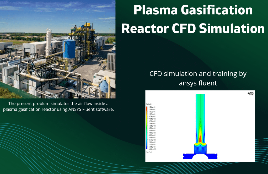
The present problem simulates the airflow inside a plasma gasification reactor using ANSYS Fluent software.
In general, plasma gasification is a process in which organic materials are converted to synthetic gas with the help of plasma. Arc-ignited plasma is used to ionize and catalyze organic matter into synthetic gas and solid waste.
These operations are commonly used for waste remediation and the evaporation of biomass and hydrocarbons such as coal and petroleum sands.
The present model is designed in two dimensions using Design Modeler software. The model consists of a symmetrical compartment that has two edges as inputs on both sides and one edge at the top as an outlet.
The meshing has been done using ANSYS Meshing software, and the mesh type is structured. The element number is 8711.
Plasma Methodology
Fluid flow enters the chamber from two inlets on either side of the reactor at a velocity of 0.1 m/s and a temperature of 2000 K and exits at the top of the reactor at a pressure equal to atmospheric pressure. Also, the side walls of the reactor have a constant temperature equal to 600 K.
Plasma Conclusion
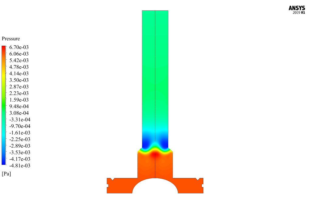
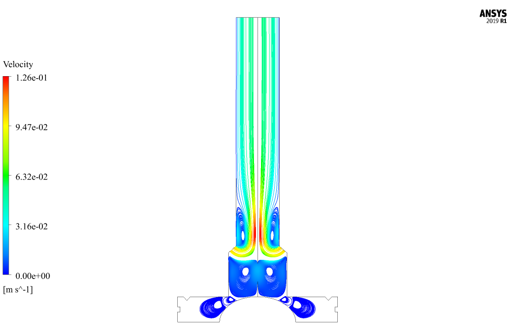
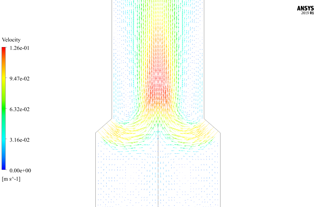
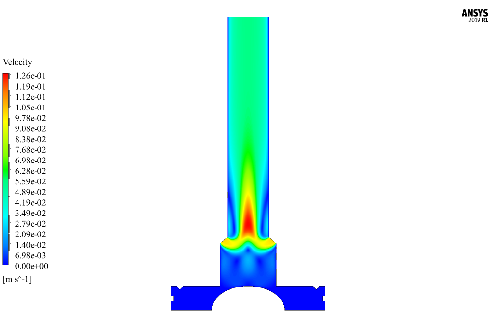
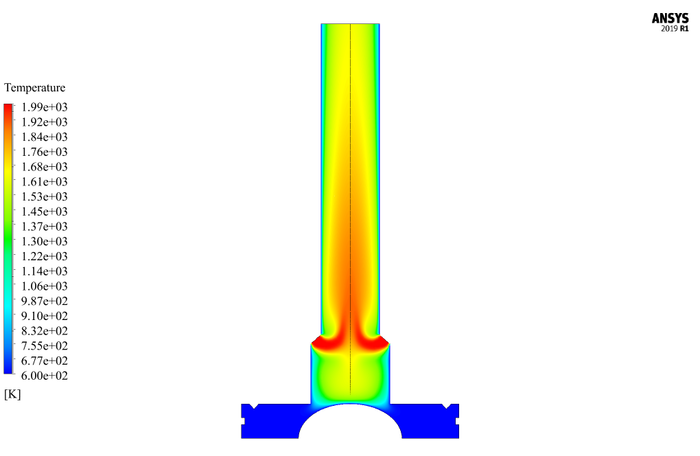
At the end of the solution process, two-dimensional contours related to pressure, velocity, and temperature, as well as path lines and velocity vectors, are obtained. The pressure decrease when the flow gets close to the outlet.
The maximum velocity occurs in the middle of the device, where the fluid flows from two separated inlets collide. Also, based on the project description, the maximum temperature is located at inlets.

Jerrold Hoeger DVM –
I’m impressed by the intricate detail in the plasma gasification reactor simulation. The temperature profiles seem absolutely crucial for understanding the process efficiency. Kudos to MR CFD for creating such a comprehensive learning product!
MR CFD Support –
Thank you for your positive feedback! We are delighted to hear that our Plasma Gasification Reactor CFD Simulation in ANSYS Fluent has met your expectations for learning and detail. We strive to provide the most comprehensive and practical educational materials for our customers. Should you have any further questions or need assistance with another project, please feel free to reach out.
Letitia Brekke –
The Science Behind It! – The training provided a great hands-on experience with simulating a plasma gasification reactor. It was illuminating to see how the workflow in ANSYS Fluent is arranged for such complex processes. Especially interesting was observing the effects of different inlet velocities and their impact on temperature and pressure within the reactor. Kudos to the team for such an insightful module!
MR CFD Support –
We’re thrilled to hear that you found value in our Plasma Gasification Reactor CFD Simulation training! It’s wonderful to know that the hands-on experience and comprehensive nature of the content made for an enlightening learning experience. Thank you for your thoughtful feedback, and we appreciate your positive comments about our team’s efforts to facilitate a deep understanding of these processes. If you have any further questions or need assistance in the future, please don’t hesitate to reach out.
Dr. Lolita Feil PhD –
I found the simulation fascinating and particularly the detailed outcome with pressure, velocity, and temperature contours. I’m curious if other chemical reactions specific to gasification were also simulated along with the flow and thermal simulation, or were they beyond the scope of this project?
MR CFD Support –
In this simulation project, the focus is on airflow dynamics and temperature distribution within the plasma gasification reactor. The chemical reactions specific to gasification, such as the breakdown of organic material and synthesis gas production, are complex and are often simulated using additional simulation modules or software designed for reacting flows. In this particular simplified two-dimensional model, such reaction kinetics may not be fully captured, and they indeed might be considered beyond the scope of this specific simulation demonstration using ANSYS Fluent.
Talia Mosciski –
Incredbly insightful training on Plasma gasification! I really enjoyed the clear explanations of the process and the detailed modeling aspect of it.
MR CFD Support –
Thank you for your kind review! We are delighted to know our training on Plasma Gasification was able to provide clear and detailed insights. We always strive to offer informative and practical instructions to help our customers. Your satisfaction is our top priority!
Hermann Padberg –
Wow, I’m impressed by the thoroughness of the plasma gasification simulation tutorial by MR CFD! This training has been an invaluable resource for understanding the complex interactions in plasma reactors. The detailed explanations paired with visuals like contours and vector paths make it very engaging. Impressive work!
MR CFD Support –
Thank you! We are thrilled that our Plasma Gasification Reactor CFD Simulation training was so helpful to you. It’s great to hear that the materials provided an in-depth understanding and made a complex subject more accessible. We appreciate your feedback!
Nora Hoeger –
What are the applications of plasma gasification based on this simulation?
MR CFD Support –
The plasma gasification simulation is intended for applications in waste remediation to turn organic material into synthetic gas. It’s used to break down biomass, municipal solid waste, and even hydrocarbons like coal and petroleum sands, creating cleaner synthetic gas and reducing solid waste volume.
Dr. Alfredo Altenwerth –
I found the temperature profiles fascinating. Was it possible to see clearly how the plasma affected temperature gradients within the reactor in the simulation results?
MR CFD Support –
In the results of the simulation, clear temperature gradients can be observed, indicating how the plasma enhances the temperature within the reactor. These gradients are especially noticeable around the areas where the plasma interacts with the inflowing gas, showing the regions of highest thermal activity.
Miss Carli Stark MD –
The course was excellent! The plasma gasification reactor simulation walkthrough was straightforward and informative.
MR CFD Support –
Thank you for your positive feedback! We’re thrilled to hear that you found the plasma gasification reactor simulation course both informative and easy to follow. We strive to provide clear and practical training for our users, and it’s great to know that we’ve succeeded. If you have any more questions or need further assistance, please don’t hesitate to reach out.
Polly Kling IV –
The detailed visualization of the gasification process is really impressive. The contours really helped in understanding the temperature and velocity changes within the reactor.
MR CFD Support –
We appreciate your positive feedback! It’s wonderful to hear that our simulation and visualization tools were helpful in enhancing your understanding of the plasma gasification process. If you have any questions or need further information about our products and simulations, feel free to ask. Thank you for choosing MR CFD for your learning journey.
Marisol Leannon –
I’m incredibly impressed with the clarity and detail of the plasma gasification reactor CFD simulation. The visual representation of velocity and temperature contours were really helpful in understanding the process.
MR CFD Support –
Thank you so much for your kind words! We’re thrilled that our simulation was able to provide the clarity and detail you needed. Your compliment encourages us to continue delivering high-quality products that help our customers. If you need any more information or assistance, don’t hesitate to contact us.
Dr. Lynn Skiles –
I’m intrigued by the outcome of the plasma gasification reactor simulation. Could you provide more detail on the effect of the refractories lining the reactor walls on the process?
MR CFD Support –
In the plasma gasification reactor simulation, the refractory lining material has been taken into consideration by setting constant temperature boundary conditions on the reactor walls at 600 K. The refractory material helps contain the high temperatures within the reactor chamber and ensures the durability of the structure under harsh processing environments. Additionally, the impact of the reflected heat from the refractory walls enhances overall temperature uniformity, aiding in the efficient gasification of the organic materials.
Jamarcus Cole –
The instruction and detail provided in this CFD course have shed light on plasma gasification more than any resource I have previously encountered. The hands-on approach really helped solidify my understanding of plasma behavior in gasification reactors.
MR CFD Support –
Thank you so much for your kind words! We’re delighted to hear that our Plasma Gasification Reactor CFD Simulation course has provided you with valuable hands-on experience and a deeper understanding of plasma processes. At MR CFD, we strive to deliver comprehensive and practical knowledge to our learners. Your feedback motivates us to keep improving our educational materials. If you have further inquiries or need assistance in your learning journey, do not hesitate to reach out.
Edmond Batz –
I was thoroughly impressed with the
MR CFD Support –
We’re thrilled to hear you were impressed with our Plasma Gasification Reactor CFD Simulation training! Thank you for your positive feedback, and we’re glad the product met your expectations.
Ansel Williamson –
I was so impressed with the results of the plasma gasification CFD simulation! The visual representations and detailed analysis clearly demonstrate the efficiency of the reactor design. Understanding how plasma technology can convert waste to energy is fascinating, and seeing it in action through these simulations was incredible!
MR CFD Support –
Thank you for your kind words! We are thrilled to hear that you found the plasma gasification reactor simulation helpful and insightful. We are proud to provide products that not only demonstrate complex processes but also aid in the understanding of environmentally impactful technologies. If there’s anything more you wish to explore or learn about plasma gasification, we’re always here to assist!
Lysanne Stanton I –
The training for the Plasma Gasification Reactor CFD Simulation was detailed and thorough. The visualization of airflow patterns within the reactor was fascinating, and the clear display of temperature variations helped grasp complex interactions within the system. The balance between theory and practical application and the structured approach to modelling were particularly beneficial for my understanding of plasma gasification processes. Excellent course!
MR CFD Support –
Thank you for taking the time to provide your feedback. We’re thrilled to hear that our training on the Plasma Gasification Reactor CFD Simulation was able to effectively convey the critical aspects and intricacies of the simulation process. It’s gratifying to know that the course enhanced your understanding and we appreciate your compliments on the training’s approach and content clarity!
Dr. Elissa Durgan –
Wow, the detailed simulation of airflow inside a plasma gasification reactor seems like quite advanced training! I appreciate how the results were clearly explained regarding pressure, velocity, and temperature changes within the reactor. It’s also fantastic to hear that there’s a visual component with the path lines and velocity vectors being obtainable. This must provide a robust understanding of the process.
MR CFD Support –
Thank you for your positive review! We’re delighted to hear that you found the simulation detailed and insightful. It’s our pleasure to provide training materials that offer a clear explanation of concepts and visual aids to enhance the learning experience. If you have any questions or need further resources, feel free to reach out!
Raquel Purdy Jr. –
The detail about the airflow entering at 2000 K – was the simulation able to accurately model the plasma arc-ignited gasification process and handle such extreme temperatures well?
MR CFD Support –
In the simulation of the plasma gasification reactor, high-temperature gas flow, such as that achieved with plasma (2000 K), is indeed incorporated in the model. The software utilizes sophisticated numerical methods capable of handling the complexities of high-temperature physics, ensuring the process is accurately simulated, including the effects of high temperatures on gas ionization and the gasification process.
Dennis Heidenreich –
The detail in the description for temperature points at different locations is great. Do you offer visual aids like animations or transient state simulations that show the process over time?
MR CFD Support –
Thank you for your kind words! Yes, MR CFD Company does provide visual aids such as animations and transient state simulations. These simulations illustrate how the variables change over time, giving a more dynamic view of the process which can be incredibly helpful in understanding the plasma gasification phenomena within the reactor.