 In A Finned Tube, Ansys Fluent Cfd Simulation Training 1")
Phase Change Material (PCM) in a Finned Tube, ANSYS Fluent CFD Simulation Training
$100.00 Internship
- The problem numerically simulates the Phase Change Material (PCM) in a Finned Tube using ANSYS Fluent software.
- We design the 3-D model by the Design Modeler software.
- We Mesh the model by ANSYS Meshing software, and the element number equals 107718.
- We perform this simulation as unsteady (Transient).
- We use the Solidification and Melting model to define phase change materials.
To Order Your Project or benefit from a CFD consultation, contact our experts via email (info@mr-cfd.com), online support tab, or WhatsApp at +44 7443 197273.
There are some Free Products to check our service quality.
If you want the training video in another language instead of English, ask it via info@mr-cfd.com after you buy the product.
Description
Description
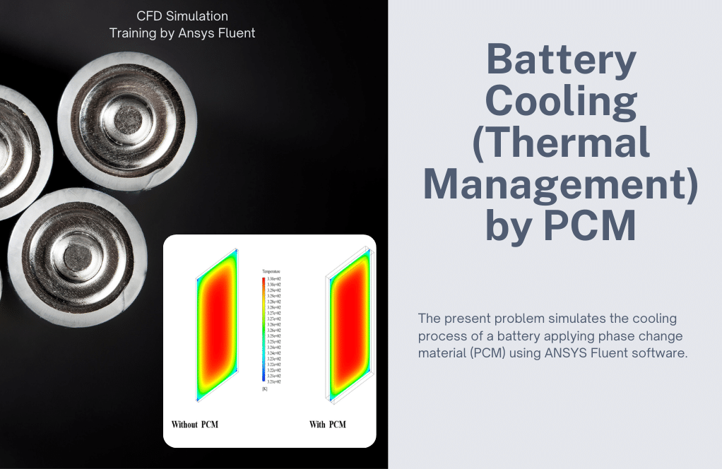
The present issue deals with the simulation of PCM using ANSYS Fluent software. We perform this CFD project and investigate it by CFD analysis.
Thermal energy storage in PCM is obtained during the phase change process, so that during the phase change from solid to liquid, it absorbs heat from the environment and during the liquid-to-solid phase change, returns heat to the environment.
PCMs have a variety of melting (Liquidus) or freezing (solidus) temperatures and are therefore used in cooling and heating systems; These materials receive solar energy in the form of latent heat and melt on warm days, and then return the heat to the environment again in the cool night, by changing the phase and solidification and melting process.
PCMs are embedded in a three-layer tube heat exchanger as a latent heat storage tank; The inner tube body and its fins are made of copper which has good Thermal Conductivity and the fluid in the inner tube is liquid silicone type and also the PCM is Erythritol.
Since the nature of the PCMs of the present model is based on the phase change between the two solid and liquid phases, a Solidification and Melting module is used for CFD simulation. The simulation process is performed over 12,000 seconds.
The purpose of the present study is to investigate the fluid and thermal behavior of the phase change materials and the fluid mass fraction in the solid-liquid mixture, based on the dimensions and physical conditions of the tube fins as well as the properties of the internal fluid.
Incoming fluid flow has a velocity of 1 m/s and a temperature equal to 343.15 kelvin. Outer walls are considered with a heat flux of 0 and inner walls are considered as coupled walls automatically by the software.
The 3-D geometry of the model was designed by Design Modeler software. To mesh the present model, we have used ANSYS Meshing software and Hybrid (structured and unstructured) mesh. The element number is 107718.
Phase Change Material Methodology
After the activation of the solidification and melting module, new thermal properties for the fluids defined in the problem will be activated, as mentioned in the table above.
Since the melting and solidification process takes place within the Erythritol material as PCM, it has a point of melting and solidification temperature as well as the latent heat rate of melting, which is a major factor in the melting and solidification process.
But while the silicon liquid does not play a role in the phase change model process, it’s melting and solidification points are equal to zero with a latent heat rate.
Phase Change Material Conclusion
At the end of the solution process, two-dimensional contours related to the temperature and mass fraction of the liquid are obtained. These contours are obtained at the time of the last second of the simulation process, the 1200s.
The contours show well that with the passage of time and the melting of the PCM material, the heat transfer has taken place well and the temperature in the center of the tubes has risen.
Reviews
You must be logged in to post a review.
Kirsten Keebler –
What is the principle behind the simulation of Phase Change Material (PCM) in a finned tube?
MR CFD Support –
The simulation is based on the principle of latent heat storage. The PCM absorbs or releases heat during phase change, which is effectively captured in the simulation.
Allison Hoeger –
Can i ask how the heat transfer is modeled in the simulation?
MR CFD Support –
The heat transfer is modeled using the energy equation in ANSYS Fluent, which takes into account conduction, convection, and phase change heat transfer.
Mr. Weldon Herman –
I’m impressed by the in-depth understanding this simulation seems to provide about the behavior of PCM. Were there any challenges regarding mesh generation due to the complexity of the finned tube geometry?
MR CFD Support –
We applied a hybrid mesh approach to ensure accurate results while managing the computational cost, but indeed, finned tube geometries can present challenges for meshing. Our effective strategy involved a combination of structured and unstructured mesh to accurately resolve the complex geometry and correctly predict the thermal and fluid behaviors of the PCM.
Ethel Schaefer II –
Can you explain how the solidification and melting module is set up in the PCM simulation using ANSYS Fluent?
MR CFD Support –
In the PCM simulation using ANSYS Fluent, the solidification and melting module is set up to account for the phase change between solid and liquid states of the PCM. This is done by defining the material properties such as the melting point, solidification temperature, latent heat of fusion, and thermal-physical properties both for the PCM and the fluid used. The solidification and melting temperatures, along with latent heat rates unique to the Erythritol PCM, enable Fluent to model the heat transfer and phase change accurately during the simulation period.
Prof. Serena Bahringer PhD –
Great
Mossie Altenwerth –
The explanation of the simulation was quite clear, but I’m curious if gravity was considered in the simulation? What impact does it typically have on melting and solidification in this context?
MR CFD Support –
In the PCM simulation within a finned tube as described, gravity can indeed have an impact on the melting and solidification process, as natural convection can occur due to density differences at various temperatures. Whether gravity is included in this specific simulation would depend on the aims of the study and the relevant physical conditions being modeled. Typically, including gravity can result in a more accurate depiction of how the material behaves in a real-world, gravity-affected environment.
Miss Hallie Osinski –
I learned a lot about phase change materials from this simulation! It’s fascinating to see how PCM can be effectively used in thermal systems. The detailed explanation of the methodology and the conclusion was especially helpful for understanding the process of heat transfer.
MR CFD Support –
We’re truly pleased to hear that the simulation on Phase Change Material in a Finned Tube provided you with valuable insight and understanding. Thank you for highlighting the aspects of the methodology and conclusions you found helpful! Your appreciation motivates us to continue delivering high-quality learning products. If you have any more questions or need further assistance, feel free to reach out.
Prof. Darrell Leffler –
The training you’ve provided on the PCM in a finned tube using ANSYS Fluent is outstanding! The description clearly demonstrates the complexity of the thermal energy storage process using phase change materials, and I especially appreciate the in-depth methodology and final analysis shown in the conclusion.
MR CFD Support –
Thank you so much for your kind words! We’re glad to hear that the training material on phase change materials in a finned tube was informative and helpful. Our aim is to provide comprehensive and understandable CFD simulation training. If you have any further queries or need additional learning resources, please don’t hesitate to reach out.
Mr. Maximo Von –
What are the key parameters considered in the simulation?
MR CFD Support –
Key parameters in the simulation include the properties of the PCM, the geometry of the finned tube, and the boundary conditions such as the heat transfer rate.
Fern Schinner II –
The review I learned a lot about simulation using PCM materials using your training module. It was insightful regarding the application for cooling and heating systems. Thank you for putting together such an informative simulation training.
MR CFD Support –
We are delighted to hear that the training on PCM in a Finned Tube offered by MR CFD Company has been educational and informative to you. We sincerely appreciate your kind words and are thrilled that it has enlightened you about the practical applications of PCM materials in thermal systems. Thank you for choosing our training module, and we look forward to supporting your ongoing learning journey.
Prof. Erica Stoltenberg Jr. –
Amazing learning experience! The CFD simulation of PCM in a finned tube shows the complex dynamics of heat transfer during phase changes. Being able to see the melting and solidification process with such detail bridges the gap between theoretical knowledge and practical understanding. Well-crafted simulation and comprehensive analysis.
MR CFD Support –
Thank you very much for your positive feedback! We’re delighted to hear that you appreciated the level of detail and found the simulation educational. It’s our goal to provide valuable insights through our CFD simulations. If you ever have more questions or need further information, we’re here to help. Thanks again for choosing our learning products!
Prof. Kenneth Powlowski II –
The assistance I’ve received from your customer service has been outstanding. Responses have always been timely and beneficial.
MR CFD Support –
We’re delighted to hear that you’ve had such a positive experience with our customer service. We strive to provide timely and helpful responses to all inquiries, and your feedback is greatly appreciated
Rubie Champlin –
MR-CFD, could you please send me the geometrical file?
MR CFD Support –
contact our experts via email (info@mr-cfd.com), online support tab, or WhatsApp at +1 (903) 231-3943.
Austin Bailey –
I’m very pleased with the PCM in a Finned Tube CFD Simulation training provided by your company. The in-depth content on how these materials absorb and release heat is not only engaging but also extremely informative. Being able to see thermal behavior and the phase changes of PCMs in such visual detail has greatly enhanced my understanding. Brilliant work on meshing and simulation setup as well!
MR CFD Support –
Thank you so much for your positive feedback! We’re thrilled to hear that our training has enriched your understanding of PCM behavior and the phase change process. Your comments on the meshing and simulation setup are greatly appreciated. It’s rewarding to know that our efforts to provide comprehensive and engaging content have been successful. If you ever have more questions or need further assistance, don’t hesitate to reach out.
Rickie Lebsack –
What is the reason behind using Erythritol as the PCM material for this CFD simulation?
MR CFD Support –
Erythritol is selected as the PCM (Phase Change Material) due to its favorable thermophysical properties, including a suitable phase change temperature and a high latent heat of fusion, which make it effective for thermal energy storage in applications like the one studied in this simulation.
Alena Barton –
Is there a way to visualize the phase transition of PCM in the simulation, and if so, what does it show?
MR CFD Support –
Yes, the phase transition of PCM can be visualized in the simulation through two-dimensional temperature and mass fraction contours. These visualizations show the progression of the melting process over time and how the heat transfer occurs, particularly highlighting that as the PCM material melts, the temperature increases towards the center of the tubes.
Kory Trantow –
I’m impressed by the detailed simulation of PCM and the use of ANSYS Fluent software for this purpose. The ability to track the heat storage during phase changes and the precision of the hybrid mesh used in the CFD project are commendable. This kind of simulation is crucial for the advancement of energy storage methods, and the hands-on approach in learning to conduct such processes is invaluable for gaining practical skills. Great job on successfully simulating this complex thermal process!
MR CFD Support –
Thank you so much for your kind words! We’re thrilled to hear that you found the simulation detailed and enlightening. Our goal is to provide comprehensive training that equips our users with valuable practical skills. It’s wonderful to know that our efforts in simulating energy storage methods have been appreciated and that you had a positive experience with our CFD project. If you have any further queries or need more assistance, feel free to reach out to us!
Ms. Gabrielle Sanford DVM –
I found the use of PCMs in thermal storage fascinating. The training helped me understand the mechanisms behind the heat absorption and release during the phase change processes. Great use of a finned tube setup in the simulation to maximize thermal transfer efficiency.
MR CFD Support –
Thank you for your positive review! We’re delighted to hear that our training on PCM’s heat absorption and release mechanisms within a finned tube setup provided you with valuable insights and a deeper understanding of thermal storage. It’s rewarding to know that the simulation was effective in illustrating these concepts. We appreciate your feedback!