
Pelton Wheel Turbine, Numerical Study, Industrial Application
Original price was: $600.00.$300.00Current price is: $300.00. Internship
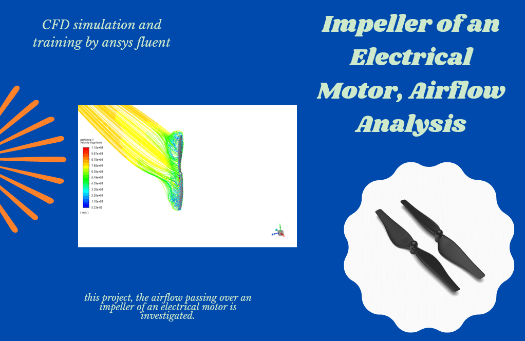
In this project, an industrial Pelton wheel turbine has been simulated and the results of this simulation have been investigated.
Click on Add To Cart and obtain the Geometry file, Mesh file, and a Comprehensive ANSYS Fluent Training Video.To Order Your Project or benefit from a CFD consultation, contact our experts via email (info@mr-cfd.com), online support tab, or WhatsApp at +44 7443 197273.
There are some Free Products to check our service quality.
If you want the training video in another language instead of English, ask it via info@mr-cfd.com after you buy the product.
Description
Pelton Wheel Turbine, Numerical Study, Industrial Application

Abstract Pelton wheel turbine
This article is about a popular impact turbine. The Pelton turbine is the only impact hydraulic turbine currently in use. According to Newton’s second law, this turbine uses a fluid jet to generate energy. This turbine is hit by a pressurized water nozzle tangentially to the bucket connected to the runner and rotates the runner.
The buckets are pairs so that in addition to the balance of force that is applied, the momentum is transferred smoothly and efficiently. The pellets are in different sizes. Large sizes are used in dams because these turbines are specifically designed for large heads, and small sizes are used to generate electricity in remote areas.

Purpose Pelton wheel turbine
In this project, a small Pelton turbine with a diameter of 300 mm and 15 buckets is simulated in ANSYS Fluent software. Also, this project aims to get the amount of torque produced in this turbine.


Pelton wheel turbine Introduction
Lester Allen Pelton, an American inventor, traveled to the American West in 1860 at the age of 30 in search of treasure and worked in a mine in northern California. At that time, most works were done with the help of steam engine power. But these engines consumed large amounts of wood as fuel.
The water cycles used in large rivers with very low efficiencies were useless in small rivers near the mine. Hence, Pelton began to design a wheel that could operate at low water flow rates.
In the mid-1870s, he built his first laboratory turbine from wood, and the first sample of real iron was installed in 1878 in a mine near Nevada. The Pelton wheel’s positive advantages and high efficiency made his invention soon reach mass production.
Pelton’s initiative was to design a separator to divide the input jet into two equal streams. The same idea increased the water cycle efficiency from about 35% to 90%. There are several types of impact turbines. But the model that Pelton invented is still the most efficient.
Pelton wheel turbine
The rotor of this turbine consists of a disk with several blades installed around it. These blades are also called plates. One or more nozzles are positioned so that the jet of water coming out of each nozzle can be thrown directly and tangentially to the disk toward the center of each plate.
A separator or splitter divides the input jet into each plate into two equal streams. These two equal streams leave the plate after passing through a curved path on the inner surface of the plate in the opposite direction to the direction of the inlet jet.
Simulation
The geometry of the simulation is drawn in ANSYS SpaceClaim software. The mesh of the present model was created by ANSYS Meshing software, which produced about 10,000,000 triangular cells. In addition, to reduce the computational cost in Fluent software, triangular meshes were converted to Polyhedral (2923341 Polyhedral meshes).
Pelton simulations are performed steady with the k-ε model is Realizable as the turbulence model; we also used the VOF model for the two-phase equation. The fluid used in this simulation is air and water for the continuous phase. Pelton rotation is performed using the mesh motion command(3000 red/s). Coupling of velocity and pressure equations is also performed using the Coupled algorithm.


Pelton wheel turbine result
This project aims to obtain the produced momentum of this Pelton and the produced lateral force to select the appropriate axis.

Looking at the chart above, we conclude that after 0.078 seconds, Pelton’s momentum reaches a constant oscillation.
| Direction | Force |
| x | -0.37569732 |
| y | -1.4908452 |
| Z | 31.86981 |
Reviews
You must be logged in to post a review.
Catherine Hessel –
I’m impressed with the detail of the Pelton Wheel Turbine CFD simulation! Were any specific challenges encountered when defining the interaction between the water jet and the Pelton buckets, particularly regarding simulating the splash and spread of water after impact?
MR CFD Support –
Dear customer, we appreciate your interest! Simulating the water jet’s interaction with the Pelton buckets indeed poses a complex challenge. Accurately capturing the splash and spread of the water involves carefully defining the boundary conditions and interface treatment within the VOF model to track the interface between water and air correctly. Additionally, maintaining stability during the mesh motion for the bucket’s rotation requires precise synchronization with the flow dynamics to ensure realism and accuracy in the splash patterns.
Braeden Braun –
I am super impressed by the detail and thoroughness of the Pelton Wheel Turbine study! The approach to transform triangular meshes to Polyhedral for efficiency is particularly clever. Great work on harnessing computational power smartly.
MR CFD Support –
Thank you for your positive feedback! We’re delighted to hear that you appreciate the effort put into optimizing the mesh for our Pelton Wheel Turbine simulation. At MR CFD, we strive to provide detailed and efficient solutions to complex problems. We’re glad our work has impressed you.
River Quitzon V –
The simulation clarity and detail are impressive! However, I’m particularly curious: What kind of improvements can be made in this simulation to more closely mimic real-world scenarios for different applications of Pelton wheels?
MR CFD Support –
Our sincere gratitude for your positive feedback. To enhance the simulation’s realism, we consider incorporating variable operational conditions, such as fluctuating water pressures or flow rates as might be found in natural environments. Additionally, implementing transient simulations could provide more accurate dynamics of the Pelton wheel responding to changing loads, aiding in blueprint optimization for diverse deployment conditions.
Mr. Chelsey Runolfsdottir PhD –
Great results on the Pelton turbine simulation! It can be quite fascinating to see the direct impact of design on function, especially with historical innovations like Pelton’s design, which still hold their ground today. The detail provided really helps to appreciate the intricacies involved in modeling such complex systems.
MR CFD Support –
Thank you for your positive feedback on our Pelton turbine simulation study. We strive to provide detailed and accurate simulations to help demonstrate the principles behind the function of these turbines. We are pleased to know that the historical context and the complexity of the modeling were appreciated. If you have further questions or need assistance with similar projects, feel free to reach out to us.
Bennett Connelly –
I’m fascinated by how Pelton wheel simulations can replicate real-world outcomes. Could you detail the specific steps involved in achieving accurate torque calculation for this Pelton turbine?
MR CFD Support –
To accurately calculate the torque produced by the Pelton wheel turbine in this simulation, several key steps are followed. These include setting up boundary conditions accurately, using an appropriate mesh (in this case, polyhedral meshes), selecting the right models like the k-
ε model for turbulence and the VOF model for the two-phase flow, and employing mesh motion for the rotating part of the Pelton turbine. Additionally, there is the coupling of velocity and pressure equations using the algorithm provided in ANSYS Fluent, ensuring that predicted momentum and forces are accurate. These precise steps taken in ANSYS Fluent lead to a reliable estimation of torque in the turbine.
Tracey Conroy III –
I’m impressed with how precise the simulation was for the Pelton Wheel Turbine, particularly in the application of the forces and the momentum observed. It’s incredibly detailed and seems accurate in relating the physics of Newton’s laws to the real behavior of the turbine. Nicely done!
MR CFD Support –
Thank you for your kind words! We put a lot of effort into ensuring our simulations are as close to real-life behavior as possible, taking into account various physical laws and phenomena. Your feedback is much appreciated, and we’re glad to know the meticulous details of the Pelton Wheel Turbine simulation met your expectations.
Charity Gottlieb –
Thanks for the in-depth learning material! The step-by-step guide through the CFD simulation of the Pelton Wheel Turbine in ANSYS Fluent was incredibly helpful. Understanding how Pelton optimized the efficiency of his turbine design through the use of a fluid jet impacting the runner really solidified my grasp of fluid dynamics applied in an industrial context.
MR CFD Support –
We are thrilled to hear that you found our guide on the simulation of the Pelton Wheel Turbine informative and valuable. It’s always great to know that our products are enhancing understanding and contributing positively to the learning experience of our customers. Thank you for your feedback!
Ashton Kuhlman –
This product truly captures the intricacies of simulating a Pelton wheel turbine. The details of the Pelton wheel model, the simulation setup, and the comprehensive use of various programs in ANSYS to boost efficiency speak volumes of the depth of the study. It is gratifying to see how the legacy of Lester Allen Pelton has been honored through meticulous numerical analysis, ensuring both historical reverence and cutting-edge application.
MR CFD Support –
Thank you for your positive feedback on our Pelton Wheel Turbine Numerical Study. We are pleased to hear that you appreciate the depth and thoroughness of the analysis presented. Our goal is to provide a profound understanding of such engineering marvels through high-quality simulations. Your acknowledgement of the historical context and satisfaction with the product encourages us to continue delivering high-caliber learning materials. Thank you for choosing our services.
Miss Nannie Toy –
I’ve learned a great deal from this study! The setup sounds complex and the results are impressive. Could you tell me the advantage of converting triangular meshes to Polyhedral in the context of CFD simulations?
MR CFD Support –
Converting triangular meshes to Polyhedral meshes in CFD simulations can offer several advantages. Polyhedral meshes tend to provide higher accuracy with a lower number of cells compared to triangular meshes, resulting in more efficient computations. This is because polyhedral cells have more faces, allowing for better approximation of gradients and a reduction in numerical diffusion. As a result, simulations often converge faster, saving both time and computational resources while maintaining or even improving result precision.
Fannie Block MD –
I found the detailed simulation approach and the innovative historical background very insightful. The concatenation of prehistoric innovations with advanced simulation techniques provided me with a rich understanding of the Pelton wheel technology. The numerical results of the generated forces and moments provide clear insights into the practical application of the Pelton turbine in industrial settings. I believe this can form a strong foundation for future explorations in turbine optimizations.
MR CFD Support –
Thank you for your appreciation. We’re glad to hear the combination of historical context and detailed simulation methodology provided you with valuable insights. It’s always rewarding to know our content is fostering a deeper understanding and potentially paving the way for future advancements in Pelton turbine applications. If you ever have further feedback or interest in our other learning products, we’re here to support you!
Shannon Cartwright –
I greatly admire the complex simulation of the Pelton Wheel Turbine in ANSYS Fluent. The use of the k-ε Realizable model and the VOF method for the two-phase equation clearly demonstrates a deep understanding of CFD analysis required for industrial applications. The move to polyhedral meshes for efficiency is particularly impressive. Your success in determining the torque created by the turbine is commendable, showing MR CFD’s capacity to tackle intricate real-world engineering problems.
MR CFD Support –
Thank you for taking the time to review our Pelton Wheel Turbine product! We’re thrilled to know that our sophisticated simulation techniques and attention to computational efficiency have met your expectations. Your insight on CFD analysis is much appreciated, and we’re glad the results of our study provided you with the useful data needed for your applications. If you have any more questions or need further assistance, please don’t hesitate to reach out.
Jada Barton –
I just completed a simulation with the Pelton wheel model and it’s incredible to see the forces come to life on the model! Can we also track the efficiency of the turbine throughout the simulation?
MR CFD Support –
Thank you for your kind words! Absolutely, the simulation model allows us to track the efficiency of the Pelton wheel turbine by comparing the mechanical power output with the water power input throughout the simulation period. Efficiency can be calculated and analyzed to ensure that the simulation mimics the real-world operating conditions of the Pelton wheel as closely as possible.