
Heat Sink Cooling with a Porous Medium, ANSYS Fluent CFD Tutorial
$120.00 Internship
- The present problem simulates the fluid flow inside a porous medium for heat sink cooling using ANSYS Fluent.
- We design the 3-D model by the Design Modeler software.
- We Mesh the model by ANSYS Meshing software.
- The mesh type is Structured, and the element number equals 7680.
- We use the Porous Medium to study the porous effect on heat transfer.
To Order Your Project or benefit from a CFD consultation, contact our experts via email (info@mr-cfd.com), online support tab, or WhatsApp at +44 7443 197273.
There are some Free Products to check our service quality.
If you want the training video in another language instead of English, ask it via info@mr-cfd.com after you buy the product.
Description
Description
The present problem simulates the fluid flow inside a porous medium for heat sink cooling using ANSYS Fluent software. We perform this CFD project and investigate it by CFD analysis.
Studying fluid flow in porous media is one of science’s most widely used fields. A porous medium comprises mostly perforated materials and contains pores and void spaces within itself.
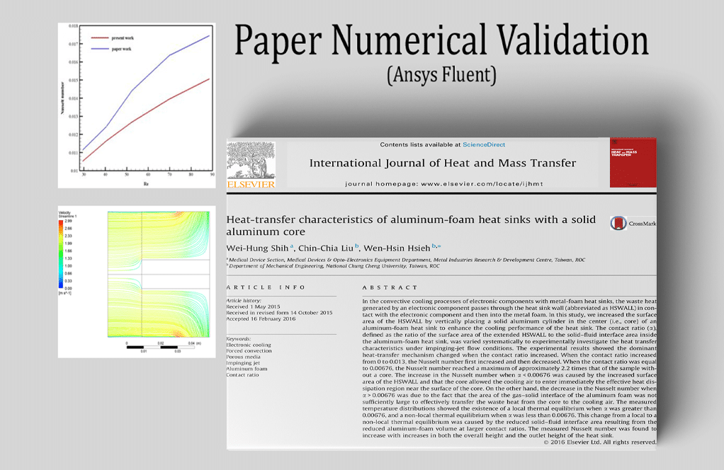
The present model is designed in three dimensions using Design Modeler software. The modeled geometry for this simulation consists of a hollow section acting as an inlet, followed by a porous aluminum foam, which is in contact with a heat source.
The meshing of this present model has been generated by Ansys Meshing software. The meshes used for this geometry are structured, and the total number of mesh cells is 7680.
Heat Sink Cooling Methodology
In this project, the fluid flow and heat transfer inside a porous medium is simulated by ANSYS Fluent software. This porous medium is in contact with a heat source, and the whole setup acts as a heat sink.
The flow enters through the inlet boundary with a velocity o 1.99 m/s and a temperature of 300K. It flows inside the porous medium to receive heat from it.
Moreover, the energy model is activated, and the RNG k-epsilon model with standard wall function is exploited for fluid flow analysis.
Heat Sink Cooling Conclusion
At the end of the solution process, we obtain the temperature, velocity, pressure, streamlines, and velocity vectors.
As seen in the pressure contour, the flow pressure behind the porous medium significantly differs from that of the outlet boundary due to the resistance that the porous medium imposes on the system.
Reviews
You must be logged in to post a review.
Dr. Claudie Prohaska –
Can this simulation be used to optimize the design of a heat sink?
MR CFD Support –
Yes, the detailed results provided by the simulation can be used to optimize the design of a heat sink to improve its cooling performance.
Dr. Juana Hackett III –
Can this simulation handle different sizes or shapes of heat sinks?
MR CFD Support –
The simulation is highly customizable and can be adapted to various sizes and shapes of heat sinks.
Chadd Schmitt –
Can the simulation model the effect of forced convection on the heat sink performance?
MR CFD Support –
Yes, the simulation can be adjusted to model the effect of forced convection, which can significantly improve the cooling performance of the heat sink.
Clair Hamill DDS –
Can the simulation handle different types of porous materials?
MR CFD Support –
Yes, the simulation can be adjusted to model different types of porous materials by changing the properties of the medium.
Dr. Rachelle Kunde DDS –
The presentation of results in thermal analysis is crucial. How are the results displayed in training for this heat sink cooling simulation?
MR CFD Support –
In the training for the heat sink cooling simulation, the results are displayed through various contours and plots. This includes temperature distributions, velocity fields, pressure contours, streamlines, and velocity vectors. These visualizations are designed to help understand how the fluid flow and heat transfer interact within the porous medium and how they impact the overall cooling performance. Moreover, the training likely discusses interpreting these contours in the context of the heat sink’s efficiency and effectiveness.
Heath Thompson –
I was impressed by how well the heat distribution was illustrated in the results. Great learning material for understanding the cooling process through porous mediums.
MR CFD Support –
Thank you for your positive feedback! We’re glad to hear that our simulation helped clarify the heat distribution in porous mediums for cooling applications. If you need further assistance in your learning journey or have any more questions, don’t hesitate to reach out.
Miss Mellie Cole MD –
I am thoroughly impressed with the clarity and detailing of the streamlines and velocity vectors in the heat sink model! The simulation results made it super easy to understand the heat transfer within the porous medium.
MR CFD Support –
Thank you for your kind words! We are thrilled to hear that our simulation results proved helpful and clear in demonstrating the heat transfer process in the porous medium heat sink. Your positive feedback motivates us to continue delivering high-quality CFD learning material.
Arvel Labadie –
I found your tutorial quite detailed, especially the explanation about the setup and methodology. I honestly compliment the clarity and practical relevance of the Heat Sink Cooling simulation tutorial provided by MR CFD Company.
MR CFD Support –
We’re grateful for your positive feedback! It’s excellent to hear that our Heat Sink Cooling tutorial was clear and beneficial to you. We always strive to provide practical and comprehensive learning materials. Thanks for choosing MR CFD for your learning journey!
Rosina Muller –
The tutorial on heat sink cooling using porous medium was instructive! The methods used to track the change in temperature and pressure throughout the system were particularly impressive.
MR CFD Support –
Thank you so much for your positive feedback! We’re thrilled to know that you found our tutorial on heat sink cooling in a porous medium to be helpful and effective in demonstrating the changes in temperature and pressure. Our goal is always to provide clear and practical instructional content, so it’s great to hear we met that for you!
Colten Heidenreich –
This CFD tutorial was well-structured and informative. I particularly appreciated the clear description of the porous medium setup and the comprehensive explanation of the energy model application.
MR CFD Support –
Thank you for your positive feedback! We’re glad to hear that the tutorial on heat sink cooling with a porous medium met your expectations and proved helpful. If you need any further assistance or information on such simulations, don’t hesitate to reach out.
Emmie Stoltenberg IV –
The tutorial was incredibly well-crafted. I was amazed to see how accurately the simulation modeled heat dispersion in the porous medium and how the tutorial walked through each step thoroughly!
MR CFD Support –
Thank you for your positive feedback! We are thrilled to hear that the tutorial was able to guide you effectively through the simulation process and that you were satisfied with the accuracy of our heat sink cooling model. If you have any more questions or need further assistance, feel free to reach out. Happy simulating!
Prof. Elenora Hill Jr. –
I’m impressed by the detail in the simulation and interested to know if the heat transfer coefficients for the porous material were fixed or estimated during the process?
MR CFD Support –
In the simulation performed by MR CFD, the heat transfer coefficients within the porous medium, such as the effective conductivity, are usually predefined based on the material’s properties (in this case, aluminum foam). They can also be estimated or adapted based on experimental data or empirical correlations during the CFD project setup. The specific approach in this scenario is not detailed, but generally, CFD analyses allow for precise control over these parameters, whether they are fixed or require estimation.
Beth Jast III –
I was amazed by how clear the tutorial made the concept of porous media simulation! It’s enlightening to understand the fluid dynamics and heat transfer interplay within a heatsink. Great work!
MR CFD Support –
Thank you so much for your kind review. We’re thrilled to hear that you found our tutorial on heat sink cooling with a porous medium so clear and helpful. It’s our goal to make complex CFD concepts accessible and understandable for everyone. We appreciate your feedback!
Johnpaul Cruickshank –
I found the Heat Sink Cooling with a Porous Medium simulation to be extremely insightful in understanding the heat transfer process in porous materials! The visualizations provided by the streamlines and velocity vectors made it much easier to conceptualize how the heat dissipates. Great job to the MR CFD team for setting up such an intuitive learning tool.
MR CFD Support –
Thank you for your kind words! We’re delighted to hear that our Heat Sink Cooling with a Porous Medium simulation has provided you with a clear understanding of heat transfer in porous materials. Our team always strives for clarity and insight in our simulations, and it’s great to know that the visualization tools helped in your learning process. Your appreciation motivates us to continue producing high-quality learning products. If you have more feedback or need further assistance, don’t hesitate to reach out!
Cullen Medhurst –
This CFD simulation of the heat sink with a porous medium sounds fascinating! The use of ANSYS Fluent seems to have provided detailed insights into the behavior of the fluid flow within the heat sink.
MR CFD Support –
Thank you for your review! We’re delighted to know that you find the heat sink CFD simulation with a porous medium fascinating and appreciate the capability of ANSYS Fluent in providing detailed insights. It is our goal to deliver comprehensive analysis tools for thermal management solutions. Your positive feedback motivates us to continue creating high-quality simulations.
Dr. Anika Hintz MD –
I’m blown away by how comprehensive this tutorial is! It provided me with a clear understanding of simulating heat transfer and fluid flow inside a porous medium. The structured mesh and the detail in visualizing temperature, velocity and pressure was particularly useful for getting a grasp on the process.
MR CFD Support –
Thank you for your positive feedback! We’re delighted to hear that our tutorial on Heat Sink Cooling with a Porous Medium has greatly helped enhance your understanding of the CFD simulation process. It is wonderful to acknowledge that the mesh detail and result visualizations were valuable in your learning journey with ANSYS Fluent.
Mrs. Elouise Fahey DVM –
I am incredibly pleased with the training on heat sink cooling with a porous medium. Kudos to your team for such a clear and detailed tutorial!
MR CFD Support –
Thank you so much for your positive review! We’re thrilled to hear that our tutorial on Heat Sink Cooling using a Porous Medium met your expectations. Don’t hesitate to reach out for further assistance with your CFD projects!
Jovani Upton –
This CFD tutorial was incredible! The clear explanation of the simulation methodology really helped in overseeing how fluid flow operates within a porous heat sink.
MR CFD Support –
We are thrilled to hear that your experience with our heat sink cooling tutorial was so positive! Accurate simulation and a thorough explanation are key for understanding complex fluid dynamics. Thank you for sharing your feedback!
Adolphus Hand –
I was very impressed with the clarity of the simulation results, especially how well you could see the effects of the porous medium on the flow and temperature distribution. The images of the pressure contours and streamlines were particularly helpful in understanding the flow behaviour within the heat sink.
MR CFD Support –
Thank you for your positive feedback! We’re glad to hear that the simulation results from ‘Heat Sink Cooling with a Porous Medium’ were clear and helpful to you. Our team puts a lot of effort into ensuring that our simulations are not only accurate, but also visually intuitive, to aid in understanding complex concepts. We appreciate your compliments on the images and they play an important role in illustrating the flow dynamics. If you have any more questions or need further clarifications on our products, please feel free to reach out.
Dr. Ashlynn Grimes –
I am impressed with the clarity of the heat sink cooling simulation tutorial involving a porous medium. The step-by-step guidance made it easy for me to set up the simulation, understand the flow characteristics within the porous material, and analyze the heat transfer process. Thank you for such a meticulously prepared simulation guide!
MR CFD Support –
Thank you for the wonderful feedback! We’re delighted to hear that the heat sink cooling simulation tutorial met your expectations and provided you with a clear understanding of the process. If you have any more questions or need further assistance in the future, please don’t hesitate to reach out. Your success is our priority!
Esther Huel –
I’m truly fascinated by the heat sink cooling simulation with the porous medium! The applied methodology seems comprehensive, and the results must provide insightful data for practical applications.
MR CFD Support –
Thank you for your kind words on our Heat Sink Cooling with a Porous Medium, ANSYS Fluent CFD Tutorial. We are glad you found the methodology comprehensive and the results insightful. We appreciate your feedback and interest in our products – it motivates us to continue delivering high-quality learning materials.
Sydnie Toy –
The tutorial for the Heat Sink Cooling with a Porous Medium looks very interesting. Does it include specific guidelines on how to set up material properties for the porous medium in ANSYS Fluent?
MR CFD Support –
Yes, our tutorial provides detailed instruction on how to define the material properties, such as porosity and permeability, specific to the porous medium in the ANSYS Fluent environment to accurately simulate its behavior when in contact with the heat source.
Harry Crooks –
I just finished the Heat Sink Cooling with a Porous Medium tutorial, and the step-by-step guidance was amazing! Thanks to MR CFD, I now understand how to map thermal profiles in complex systems.
MR CFD Support –
We’re thrilled to hear that you found our tutorial helpful and that it has enhanced your understanding of thermal mapping in porous media systems! Thank you for choosing MR CFD Company’s learning products, and we appreciate the positive feedback. If you have any more questions or need further assistance, feel free to reach out.
Mr. Jasen Marks –
This tutorial was an eye-opener for solid and fluid interactions within porous materials! The detailed steps and clear explanations made the intricate process of heat sink cooling easy to understand even for someone with basic knowledge of CFD. What a great learning tool – it enhanced my practical knowledge on dealing with porous media in simulations.
MR CFD Support –
Thank you so much for your positive feedback! We’re over the moon to hear that our tutorial on Heat Sink Cooling with a Porous Medium was helpful and easy to understand. It is very rewarding to know that it improved your knowledge of CFD analysis, specifically about fluid flow and heat transfer in porous media. If there’s anything else you’re curious about or any topic you want to delve deeper into, we’ve got plenty of resources. Don’t hesitate to continue your learning journey with MR CFD. Happy simulating!
Davon Cassin –
This heat sink cooling tutorial was a well-paced and informative guide.
MR CFD Support –
Thank you for your positive feedback! We’re glad our ANSYS Fluent CFD Tutorial on Heat Sink Cooling with a Porous Medium was helpful to you. If you have any further questions or need more tutorials, feel free to reach out to us.
Cristopher Beahan IV –
I’m absolutely thrilled with the heat sink tutorial! The explanation of fluid flow in a porous medium was enlightening, and I’m especially impressed by how effectively the simulation captures the temperature changes and streamlines within the system. Well done MR CFD!
MR CFD Support –
We’re delighted to hear that you found the tutorial enlightening and effective. It’s fantastic to know that the temperature changes and simulation results met your expectations. Thank you for taking the time to provide such positive feedback!
Dr. Jamie Kertzmann –
I recently used your Heat Sink Cooling with a Porous Medium, ANSYS Fluent tutorial, and I found the step by step approach incredibly helpful! It guided me through every detail of the simulation process. Thanks for the outstanding resource!
MR CFD Support –
Thank you for your kind words! We’re thrilled to hear that you found our tutorial helpful and that it provided you with clear guidance for your simulation. If you ever need more assistance or additional tutorials, feel free to reach out. Your success is our priority!
Prof. Marta Effertz –
Absolutely impressed with the clarity of the tutorial! The visuals for the pressure contour really helped me understand the impact of the porous medium! Thanks!
MR CFD Support –
We’re thrilled to hear that our tutorial on Heat Sink Cooling with a Porous Medium was clear and helpful. Knowing that our visuals made a significant difference is very rewarding. Thank you for your positive feedback!
Rebecca Feeney –
The demonstration of heat transfer in porous mediums was graspable and the simulation seems to cover critical aspects. Fantastic to see CFD tools handling such intricate analysis!
MR CFD Support –
Thank you for your review and the kind words! We’re thrilled to know that our tutorial on heat sink cooling using a porous medium provided you with a clear understanding of the subject. We are always here to assist with in-depth CFD analysis and simulation insights!
Cordell Farrell –
The tutorial on Heat Sink Cooling with a Porous Medium was incredibly helpful. The way you described the process and detailed the setup using ANSYS Fluid was spot on. Walking through the simulation step by step made the complicated concepts much easier to grasp. Using structured mesh to accurately represent the porous media and derive meaningful insights was quite impressive. It greatly aided in my understanding of porous media flow and heat transfer.
MR CFD Support –
We’re delighted to hear that you found our tutorial both helpful and informative! Thank you for taking the time to provide this positive feedback. If you have any further questions or need assistance with similar simulations, please don’t hesitate to reach out!
Misty Dickinson –
This tutorial really helped me understand the concepts of heat transfer in porous media. The methodology was clear, and the visuals in the results section made the data easy to interpret!
MR CFD Support –
Thank you for your kind words! We’re thrilled to hear that our Heat Sink Cooling with a Porous Medium tutorial was helpful to you in grasping heat transfer concepts, and you found the presentation of the results effective. Your feedback is appreciated!
Serenity Thompson –
I was impressed by the clear results the simulation provided! The pressure and temperature contours seem to represent the heat dissipation effect very well.
MR CFD Support –
Thank you for your review! We’re glad to hear that you found the simulation results to be clear and representative of the heat dissipation effects. The detailed contours are indeed pivotal to understanding the cooling performance of the heat sink with porous media in practical applications.
Vivien Kautzer –
The program has taught me so much about simulating heat transfer in porous materials. Thank you!
MR CFD Support –
Thank you for your feedback! We’re thrilled to hear that our tutorial on Heat Sink Cooling with a Porous Medium has been informative and helpful for you. If you have any further questions or need assistance with your CFD projects, feel free to reach out!
Mr. Shaun Mayert DVM –
I recently used the Heat Sink Cooling with a Porous Medium tutorial from MR CFD and was impressed with the level of detail in the simulation. The modeled geometry matching real-world applications and the structured meshes helped me understand how fluid flow behaves in such scenarios. The contours provided valuable insight into pressure and temperature variations. I appreciate the comprehensive investigation into heat transfer within porous media. Well done on creating a highly instructive CFD tutorial!
MR CFD Support –
We’re delighted to hear that you found our Heat Sink Cooling with a Porous Medium tutorial exceptionally informative and helpful. It’s great to know that the detail in the simulation aided your understanding and provided clear insights. Thank you for taking the time to share your positive feedback, and we look forward to providing you with more quality learning materials.