
Plate Heat Exchanger CFD Simulation, ANSYS Fluent
Free
In this project, a 3D CFD simulation of a 4-layer planar heat exchanger is investigated.
Click on Add To Cart and obtain the Geometry file, Mesh file, and a Comprehensive ANSYS Fluent Training Video.To Order Your Project or benefit from a CFD consultation, contact our experts via email (info@mr-cfd.com), online support tab, or WhatsApp at +44 7443 197273.
There are some Free Products to check our service quality.
If you want the training video in another language instead of English, ask it via info@mr-cfd.com after you buy the product.
Description
Plate Heat Exchanger CFD Simulation by ANSYS Fluent Training
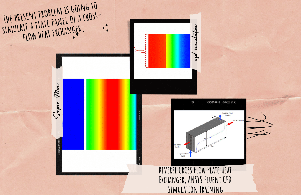
In this project, a 3D CFD simulation of a 4-layer plate heat exchanger is investigated by ANSYS Fluent software. Steady hot (T=286.2K) and cold (T=276.5K) water flows enter the planar domain and move through the heat-exchanging region. These flows exchange heat which leads to temperature difference reduction. Both flows exit the heat-exchanging domain with approximately equal temperatures (T=282K).
Plate Heat Exchanger Geometry & Mesh
The geometry of the heat exchanger is designed in Design Modeler, and grid generation is done in Ansys meshing. Inlet and outlet boundary conditions of both hot and cold flow are shown below. The mesh type is unstructured, and the element number is 2273000.


Plate Heat Exchanger CFD Simulation Settings
Critical assumptions:
- The solver type is assumed Pressure Based.
- Time formulation is assumed to be Steady.
- Gravity effects is neglected.
The following table represents a summary of the defining steps of the problem and its solution:
| Models | ||
| Energy | On | |
| Viscous | Standard K-epsilon
(Standard wall functions) |
|
| Materials | ||
| Fluid | Definition method | Fluent Database |
| Boundary conditions | ||
| Hot-Inlet | Type | Mass flow inlet |
| Mass flow rate | 0.0045 kg/s | |
| Turbulent intensity | 2% | |
| Hydraulic diameter | 0.003 m | |
| Temperature | 286.2 K | |
| Cold inlet | Type | Mass flow inlet |
| Mass flow rate | 0.00361 kg/s | |
| Turbulent intensity | 2% | |
| Hydraulic diameter | 0.003 m | |
| Temperature | 276.5 K | |
| Solver configurations | ||
| Pressure-velocity coupling | Scheme | SIMPLE |
| Spatial discretization | Gradient | Least square cell-based |
| Pressure | Standard | |
| Momentum | Second order Upwind | |
| Turbulent kinetic energy | First order Upwind | |
| Turbulent dissipation rate | First order Upwind | |
| Energy | Second order Upwind | |
| Initialization | Gauge pressure | 0 Pa |
| X velocity | 0 m/s | |
| Y velocity | 0 m/s | |
| Z velocity | -0.6451117 m/s | |
| Turbulent kinetic energy | 0.0002497015 m2/s2 | |
| Turbulent dissipation rate | 0.00308741 m2/s3 | |
| Temperature | 286.2 K | |
Results
Results, including temperature, velocity, and streamlined contours, are obtained for each of the 4 layers. Layers are planes parallel to XY Plane, which are assigned 1 to 4 as the increase of their Z. Layers 1 and 3 are regions where cold flow is heated up, and layers 2 and 4 are regions where hot flow is cooled down. The hot flow’s temperature at the inlet and outlet is 286.2 K and 281.213 K, respectively. Cold flow’s temperature at the inlet and outlet is 276.5 K and 282.725 K, respectively. It can be obtained that the heat transfer rate from the hot flow is equal to 93.8503W, and the heat transfer rate from the cold flow is equal to -93.9754W, which can be taken as equal with reasonable approximation.
You must be logged in to post a review.

Reviews
There are no reviews yet.