Plate Heat Exchanger CFD Simulation, ANSYS CFX
$100.00 Student Discount
- This problem simulates the Plate Heat Exchanger by ANSYS CFX software.
- The geometry of the present model is drawn by Design Modeler in 2.5D and then is meshed by ANSYS Meshing software.
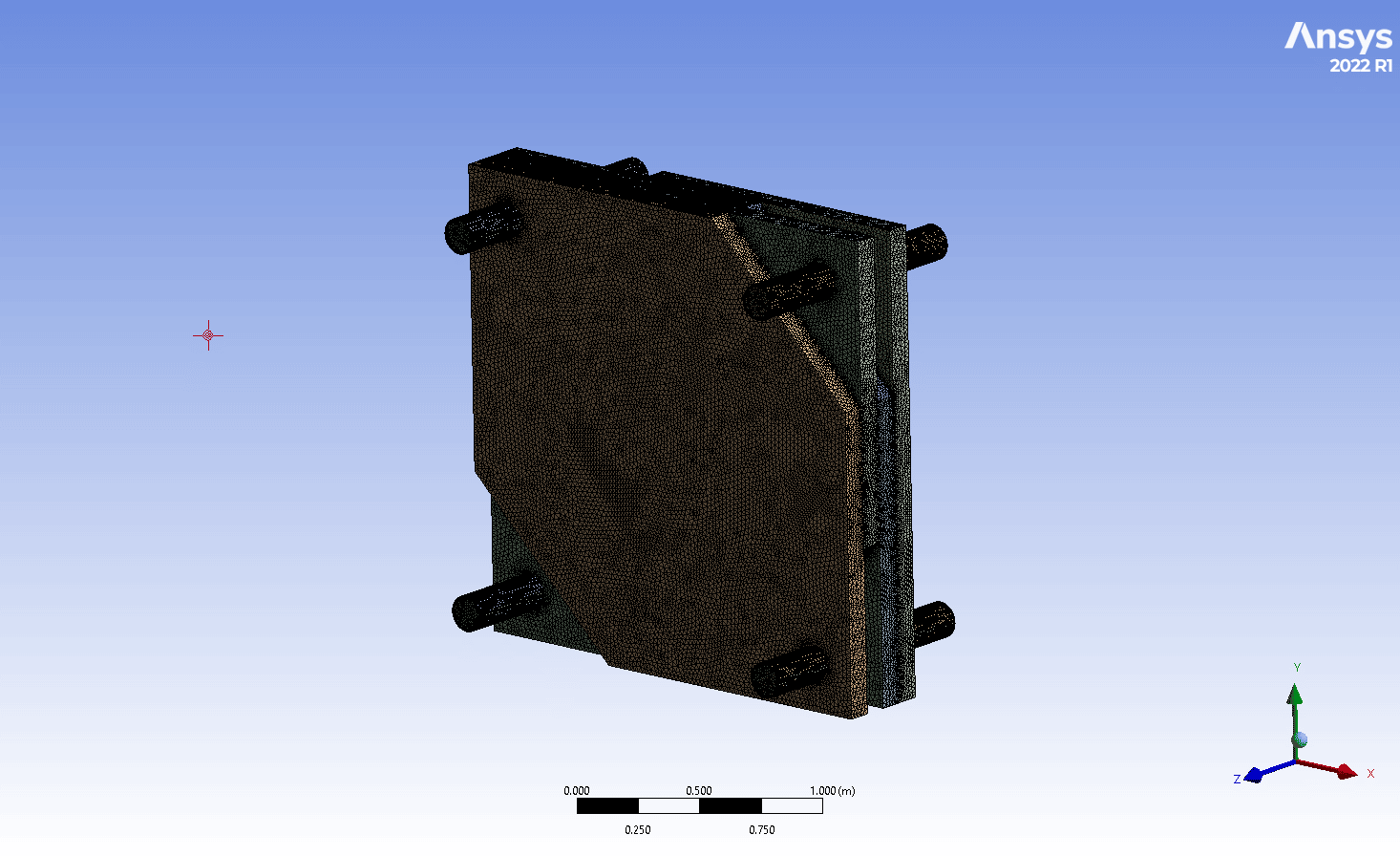
- The cell number equals 5,096,686.
- Thermal Energy is enabled to capture the temperature.
- Both Conduction and Convection happen in the domain (Conjugated Heat Transfer (CHT)).
To Order Your Project or benefit from a CFD consultation, contact our experts via email ([email protected]), online support tab, or WhatsApp at +44 7443 197273.
There are some Free Products to check our service quality.
If you want the training video in another language instead of English, ask it via [email protected] after you buy the product.
Description
Description
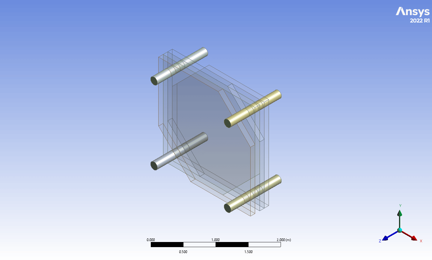
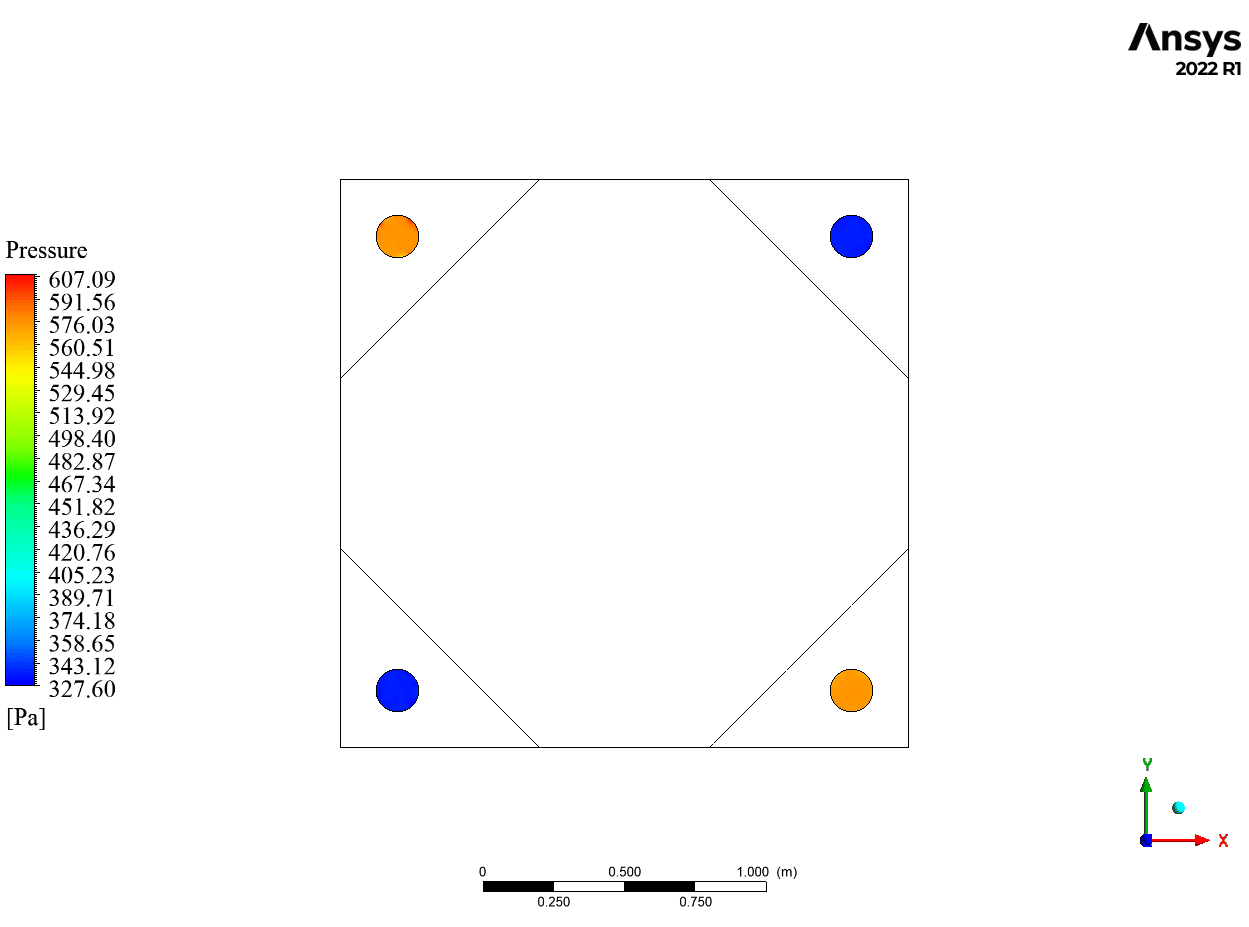
In this project, four solid plates are modeled while four pipes are placed at the corner of the plates. The fluid (water) flows through the pipes at the same velocity and at different temperatures (20 & 40 Celsius) in reverse directions.
The 2.5D geometry of the solution is modeled in Design Modeler software while all the solids and fluids are from one single part.
The solids are 2*2m, and their thickness is 0.1m; the pipe’s diameter and length are 0.15m and 1.1m, respectively.
The meshing process is done in ANSYS Meshing software. The elements are unstructured, while 5 layers of inflation is defined inside the pipes so that their total number is 5,096,686.
This CFD project is the 2nd episode of the ANSYS CFX Training Course.
Methodology: Plate Heat Exchanger CFD Simulation, ANSYS CFX
The simulation is independent of Time, so it has performed in steady state form. Moreover, the gravitational effects are ignored. There is convection between water and pipes and conduction phenomenon in the solids, transferring heat all over the domain. So, Conjugated Heat Transfer (CHT) was studied.
Heat Transfer is captured by Thermal Energy option and the turbulence model is k-Epsilon with Scalable Wall Function.
The Advection Scheme and Turbulence Numerics is set to High Resolution.
Results
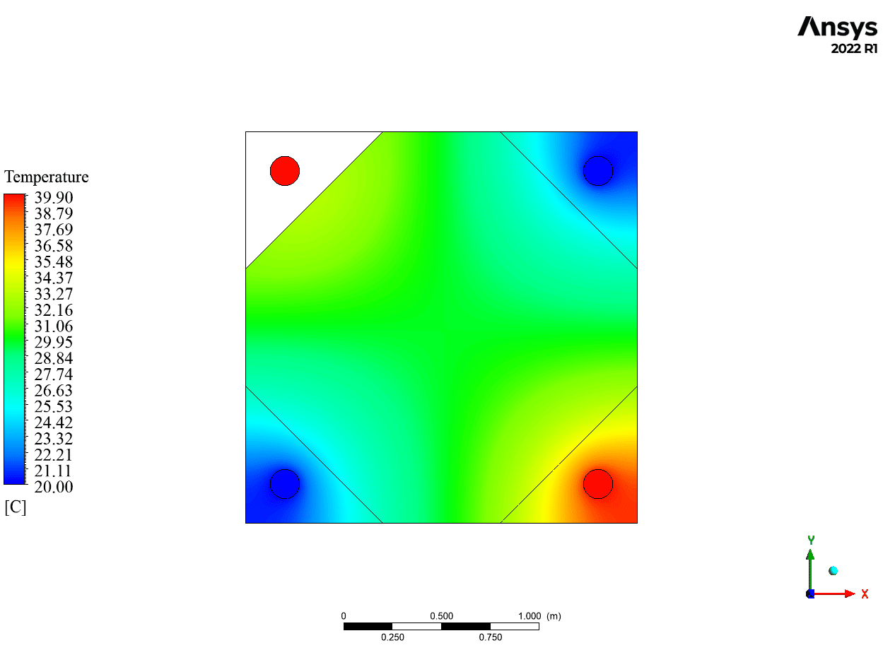
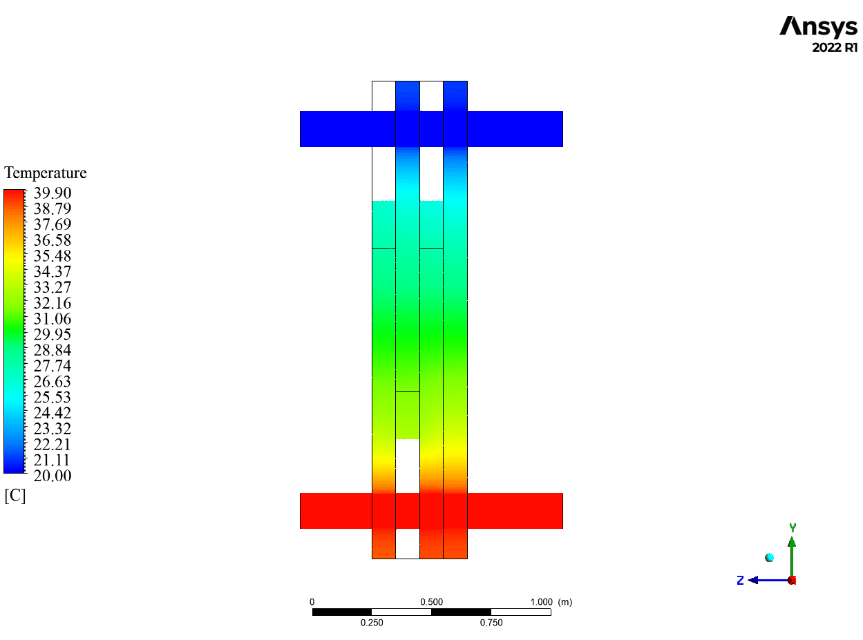
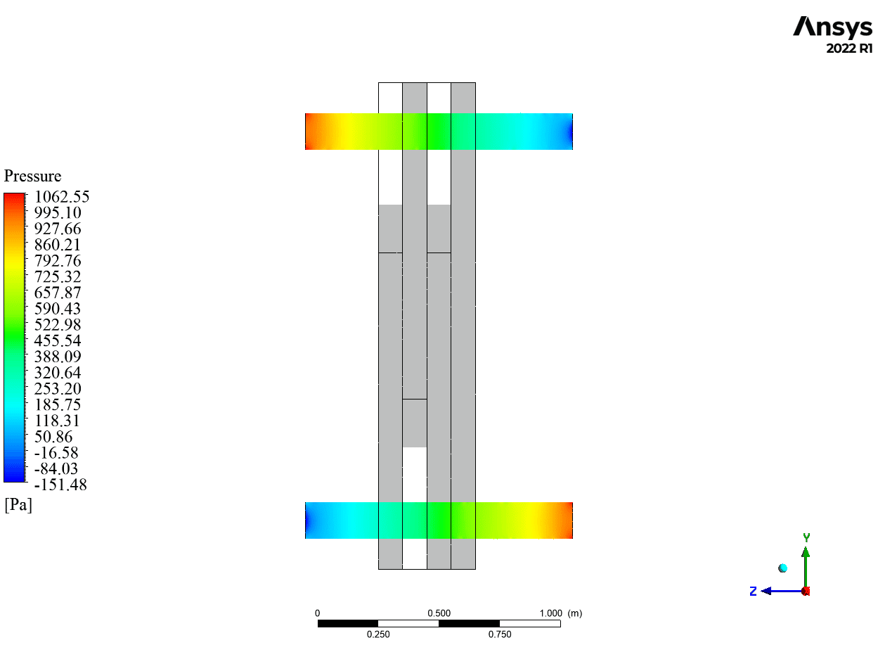
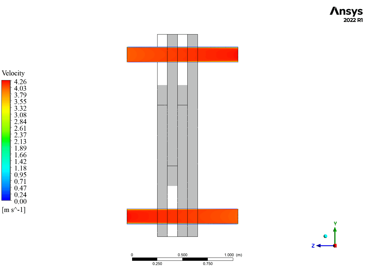
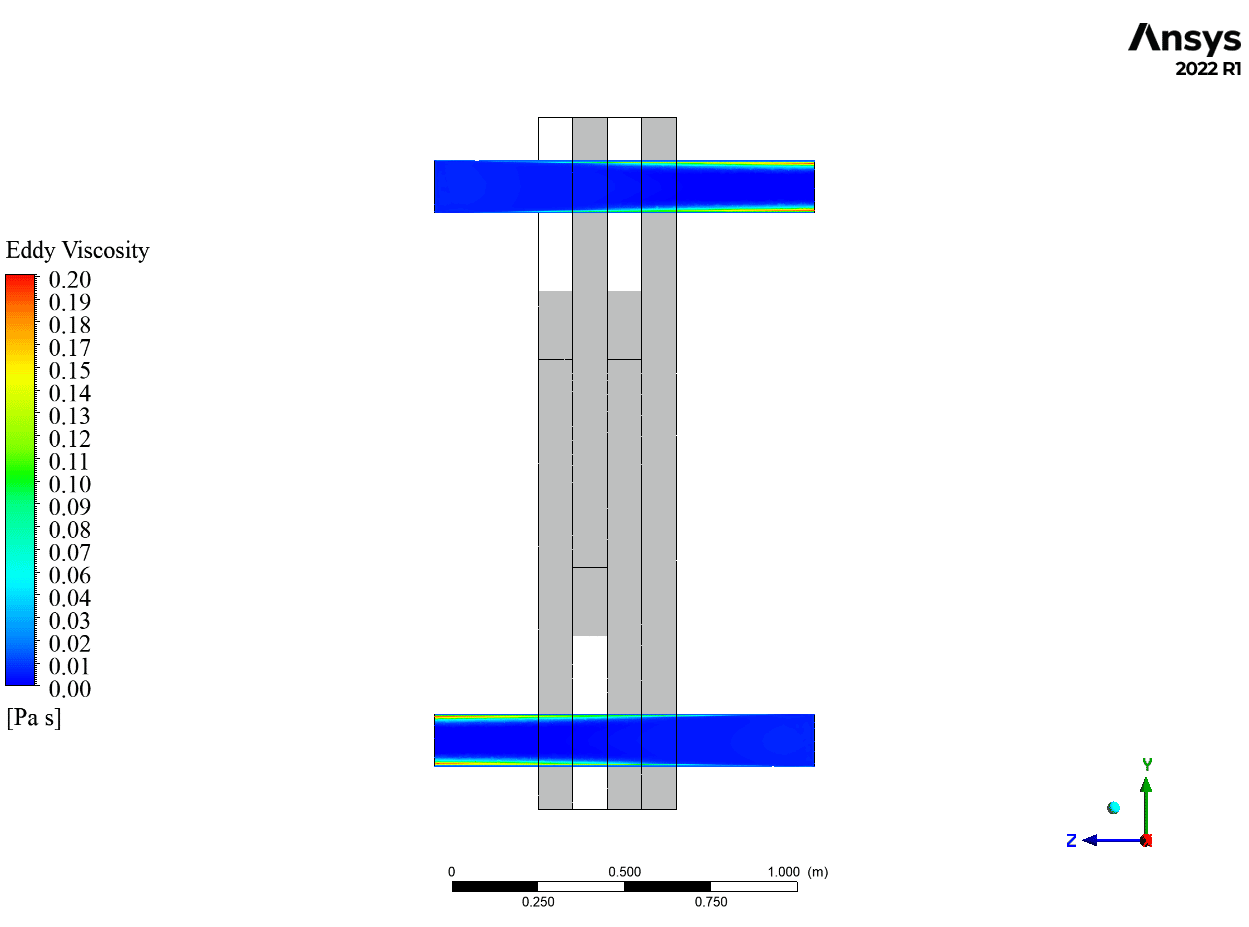
Two-dimensional contours and vectors related to water pressure, temperature, turbulence kinetic energy, and velocity are obtained at the end of the solution procedure in CFD-Post software. As shown, water flows through the pipes in opposing directions at 20 oC and 40 oC. Mentioned amounts represent cold and hot temperatures.
Convection, which occurs between the fluid and pipe walls, is the earliest mechanism of heat transfer. Then it is the turn of conduction. Due to the conduction phenomena, heat from the water is transferred within the solid.
The figures show the temperature gradient as contour lines. It should be noted that fluid velocity is a crucial factor in how heat transfer is affected. The rate of convective heat transfer increases with the velocity of the water flow.

Dion Orn –
Just finished the Plate Heat Exchanger CFD Simulation from MR CFD and I’m thoroughly impressed by the detail and clarity in explaining the CHT phenomenon. The step-by-step approach made it easy to follow!
MR CFD Support –
Thank you for your positive feedback! We pride ourselves on providing detailed and clear instructions, and we’re delighted to hear that our Plate Heat Exchanger CFD Simulation met your expectations. If there’s anything more we can help with in your learning journey, don’t hesitate to ask.
Dr. General Ritchie DVM –
I’ve thoroughly enjoyed learning from the Plate Heat Exchanger CFD Simulation coursework. It offered a clear, step-by-step approach to understanding the complex concepts of heat transfer and fluid flow in heat exchangers. The use of high-resolution schemes and inflation layers provided deep insights into accuracy aspects of CFD analysis. The balance between practical application using ANSYS CFX and theoretical knowledge was handled very well, making this course enlightening for both beginners and experienced users alike.
MR CFD Support –
Thank you so much for your positive feedback! We are thrilled to hear that our Plate Heat Exchanger CFD Simulation course met your expectations and provided valuable insights. It’s fantastic to know that you appreciated the clear, step-by-step approach and the focus on both practical application and theoretical understanding. Your compliments are greatly appreciated, and we hope that you’ll find our other courses just as enlightening. Thank you for choosing MR CFD for your learning journey!
Elna Heller –
The training on Plate Heat Exchanger CFD Simulation using ANSYS CFX was splendidly detailed. I appreciated how complex concepts were broken down to become understandable. The clear distinction between convection and conduction mechanisms and how they interact was particularly enlightening. Excellent work!
MR CFD Support –
Thank you for your encouraging feedback! We’re thrilled to hear that the Plate Heat Exchanger CFD Simulation course could impart the complex concepts in a digestible manner. Your grasp of the concepts like convection and conduction shows that the training has served its purpose. We always strive for clarity and user comprehension in our materials, so hearing that you found it enlightening is truly rewarding!
Dr. Orville Cummings –
This Plate Heat Exchanger simulation project seems very comprehensive. Can you tell me how exactly the water temperature impacts the effectiveness of the heat exchanger?
MR CFD Support –
The water temperature has a significant impact on the effectiveness of a heat exchanger. Higher temperature differences between the hot and cold fluids can increase the heat transfer rate. In this simulation, water with varying temperatures is utilized to create a temperature gradient, prompting the heat transfer. As the temperature of the hot fluid (40 Celsius) enters the exchanger, heat conduction occurs through the plate and into the colder water (20 Celsius) flowing in the opposite direction, hence affecting the efficiency of the heat exchanger.
Helga Pfeffer IV –
I’m blown away by the level of detail in the Plate Heat Exchanger CFD Simulation. The boundary mesh layer control and thorough thermal analysis are quite impressive!
MR CFD Support –
Thank you for your kind words! We’re glad to hear that our Plate Heat Exchanger CFD Simulation product was capable of impressing you with its fidelity to detail and comprehensive analysis. If you have any further queries or need assistance with other CFD projects, feel free to reach out!
Dr. Hertha Torp –
The plate heat exchanger project was expertly modeled, providing clear visualizations and deep insight into convection and conduction phenomena within the system. I appreciated the detailed setup of the heat transfer simulation. Fantastic educational material!
MR CFD Support –
Thank you for your kind words and positive feedback on our Plate Heat Exchanger CFD Simulation using ANSYS CFX. We’re thrilled to hear that our training materials met your expectations and provided valuable insights into the heat transfer process.
Efrain Walter –
I was impressed by the realism of the simulation. The inclusion of inflation layers in the pipe mesh was particularly notable; it’s details like these that can make a significant difference in capturing the heat transfer accurately.
MR CFD Support –
Thank you for your positive feedback! We are glad to hear that our attention to detail in the simulation has made an impression on you. It’s crucial for us to provide accurate and realistic results, and we appreciate your recognition of the efforts regarding the mesh configuration and heat transfer analysis. If you have more questions or need further information, please don’t hesitate to reach out.
Jettie Friesen –
I truly appreciate how the Plate Heat Exchanger CFD Simulation project illustrates the convolution of heat transfer between the fluid and the plates. The details around water temperatures, flow directions, and the effective use of the k-Epsilon model for turbulence provide valuable insights into the intricacies of heat exchange systems.
MR CFD Support –
Thank you for your kind words regarding our Plate Heat Exchanger CFD Simulation project. We are thrilled to hear that you found the information insightful and that the project was able to effectively demonstrate the complexities of heat exchange. Your feedback is very much appreciated!
Prof. Everett Waters –
The presentation of the temperature gradient is an insightful aspect of the heat exchange process. Understanding the thermal dynamics in such detail is incredibly useful.
MR CFD Support –
Thank you for appreciating the clarity and detail of the temperature gradient presentation in the Plate Heat Exchanger CFD Simulation using ANSYS CFX. We’re glad you found the thermal dynamics information useful!
Newton Waters DVM –
The level of details in the results is impressive. Having a visual representation of temperature gradients is so helpful in understanding heat transfer within the exchanger.
MR CFD Support –
Thank you for your positive feedback! We’re glad you found the visual representation and the details of temperature gradients helpful in grasping the heat transfer efficiency within the plate heat exchanger. If there’s anything else we could assist you with, feel free to reach out!
Lola Stokes IV –
I’m truly impressed by the detailed explanation and results obtained from the Plate Heat Exchanger CFD Simulation using ANSYS CFX. The approach taken to study the Conjugated Heat Transfer (CHT) methodology sounds comprehensive and ingenious.
MR CFD Support –
Thank you for your kind words and recognition of our Plate Heat Exchanger CFD Simulation. We’re thrilled to hear that you were impressed by the detailed explanation and simulation results. It’s always encouraging to receive such positive feedback from our users!
Nikita Ernser –
The Plate Heat Exchanger CFD course was fantastic! It was detailed and easy to follow. The methodology was clearly defined and the results were beautifully illustrated. I especially appreciated the explanation of convection and conduction mechanisms in heat transfer.
MR CFD Support –
Thank you so much for your positive feedback on our Plate Heat Exchanger CFD course! We’re delighted to know that you found the course well-structured and informative. Your appreciation for our illustrations and explanations truly motivates us. Thank you for choosing MR CFD for your learning journey!