
Radiation Heat Transfer in Combustion Chamber, ANSYS Fluent Training
$200.00 Internship
- The problem numerically simulates the combustion of methane and air in a combustion chamber using ANSYS Fluent software.
- We design the 3-D model by the Design Modeler software.
- We Mesh the model by ANSYS Meshing software, and the element number equals 384112.
- We use the Species Transport model to define a chemical reaction.
- We use the Discrete Ordinate (DO) to define the Radiation model.
To Order Your Project or benefit from a CFD consultation, contact our experts via email (info@mr-cfd.com), online support tab, or WhatsApp at +44 7443 197273.
There are some Free Products to check our service quality.
If you want the training video in another language instead of English, ask it via info@mr-cfd.com after you buy the product.
Description
Description
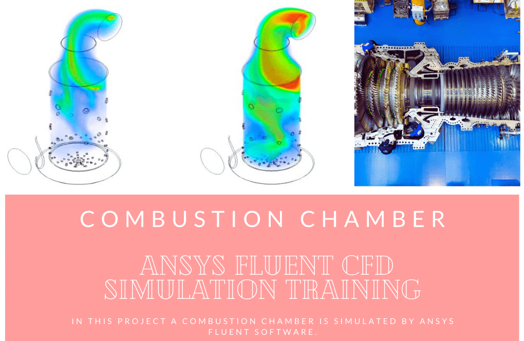
In this project, the steady combustion of methane and air in a simple extended cubical combustion chamber is investigated by ANSYS Fluent software. We perform this CFD project and investigate it by CFD analysis.
Radiation heat transfer must be considered since combustion chambers undergo extremely high temperatures.
The present model is designed in three dimensions using the Design Modeler.
The meshing of the present project has been done using ANSYS Meshing software. The element number is 384112.
Radiation Heat Transfer Methodology
In this project, the mixture’s static temperature has a maximum value of 3500 k within the chamber. Methane and air enter the domain from inlets, in which methane is injected into the domain using only one inlet.
However, airflow is injected using two inlets to achieve an approximately uniform mixture of fuel and air. The mass flow rate of air and fuel entering the domain equals 0.00468 and 0.000205 kg/s.
The chemical reaction between methane and air produces CO2 and H2O, and since the combustion is air-rich, oxygen and nitrogen are left unused at the end of the reaction. Therefore, the species transport model has been activated to simulate combustion, and volumetric reactions are enabled.
Moreover, due to the high temperature inside the combustion chamber, the heat transfer due to the radiation must also be considered; thus, the Discrete ordinates (DO) model has been enabled too.
Finally, the RNG k-epsilon model is used to solve the turbulent fluid equations. This sub-model provides the advantage of capturing intense heat flux generation inside the domain better than the other k-epsilon sub-models
Radiation Heat Transfer Conclusion
At the end of the solution process, two-dimensional contours related to the temperature, velocity, species mass fraction, streamlines, velocity vectors, etc., inside the combustion chamber are obtained. The mixture mass flow rate at the outlet is equal to 0.004885042 kg/s.
The main combustion process takes place in the combustion chamber itself. This can be explicitly seen in the contour of temperature reaction heat, which shows that the maximum temperature gradient and maximum reaction heat are observed.
Also, the occurrence of the combustion process is clear in species mass fraction contours. For instance, the CO2 mass fraction contour shows how the mass fraction of CO2 increases suddenly due to the combustion process.
Reviews
You must be logged in to post a review.
Prof. Kristoffer Larson –
How accurate is the simulation in predicting the temperature distribution in the combustion chamber?
MR CFD Support –
The simulation uses advanced models for turbulence, combustion, and radiation heat transfer, which allows it to accurately predict the temperature distribution in the combustion chamber.
Mr. Hardy Wisoky Sr. –
Is it possible to use different fuels in this simulation?
MR CFD Support –
Yes, the simulation can be adapted to use different fuels. The fuel properties can be defined in the material properties section.
Dr. Glennie Schultz Jr. –
I deeply appreciate how the Radiation Heat Transfer in Combustion Chamber training helped me understand complex thermal phenomena. The discrete ordinates model effectively elucidated heat transfer due to radiation. Superb project!
MR CFD Support –
We’re thrilled to hear you found our Radiation Heat Transfer in Combustion Chamber training so beneficial and that the discrete ordinates model clarified the radiation heat transfer process for you. Thank you for your positive feedback!
Danial Spencer –
I’m really blown away by the level of detail in this simulation and the consideration of radiant heat transfer! Just out of curiosity, were any specific design considerations given to the combustion chamber to optimize the mixing and reaction rates of the fuel and oxidizer?
MR CFD Support –
Thank you for your appreciation and inquiry! The design of the combustion chamber aimed to ensure sufficient residence time for complete combustion and good mixing of methane and air. The arrangement of inlets for methane and air optimizes the mixture’s uniformity, which contributes to the combustion efficiency. The CFD analysis, including species transport and radiation models, helps in predicting and enhancing performance, but physical design attributes like chamber shape, inlet positions, and obstruction placement would be iteratively evaluated in conjunction with CFD results to optimize the combustion process.
Lue Nienow –
What are the most significant benefits of using the Discrete Ordinates (DO) model in this kind of simulation?
MR CFD Support –
Hello! The Discrete Ordinates (DO) model is of significant benefit because it provides an accurate method for solving the radiative heat transfer equation, especially in highly absorbing and emitting media like combustion chambers. It considers the directional dependence of radiation and allows for more detailed and realistic predictions of temperature contours and heat fluxes which are crucial for combustion chamber analyses.
Dean Cole –
Thank you for the comprehensive breakdown. The way methane and air inlets are optimized for uniform mixing is clever, and including the DO model for radiation consideration in such high temperatures makes perfect sense.
MR CFD Support –
Thank you for your positive feedback on the methodology used in the combustion chamber simulation study. We are glad that you recognized the attention to detail in optimizing the mixing of methane and air as well as the appropriateness of the Discrete Ordinates model for the high-temperature environment of combustion. If you have any more questions or require further assistance, feel free to ask. Your satisfaction with our training product is our top priority!
Mr. Johnson Murray PhD –
I’m very impressed with how detailed the simulation for the Radiation Heat Transfer in a Combustion Chamber was. The methane combustion process seems expertly captured.
MR CFD Support –
Thank you so much for your positive feedback! We are thrilled to hear that you found our simulation detailed and true-to-life. It’s great to know that the efforts put into representing the methane combustion process accurately have been recognized. We appreciate you taking the time to leave such a complimentary review!
Mr. Frederick Hessel –
How does the simulation model the outlet boundary conditions?
MR CFD Support –
The simulation uses a pressure outlet boundary condition. The pressure can be defined based on your specific requirements.
Prof. Dorthy Gibson Jr. –
Just finished the ANSYS Fluent training on Radiation Heat Transfer in Combustion Chambers—astonishing results! The contour diagrams truly illustrated the intense combustion process. Appreciated the emphasis on considering heat transfer due to radiation, hugely relevant for such high-temp scenarios.
MR CFD Support –
Thank you for your positive feedback! We’re pleased to hear that you found the training materials and results exemplary. Understanding radiation heat transfer in combustion potential. If you need any more information or further assistance with your CFD learning journey, remember we’re here to help!
Mr. Timmy Daniel IV –
The tutorial on Radiation Heat Transfer in a Combustion Chamber using ANSYS Fluent was incredibly insightful! The step-by-step process made it easy to understand how to properly set up the Discrete Ordinates model for accounting for radiation. The use of species transport model for combustion simulation was also well explained.
MR CFD Support –
Thank you for your positive feedback! We’re glad the tutorial on how to simulate radiation heat transfer in a combustion chamber using ANSYS Fluent was clear and helpful for you. It’s great to hear that the explanation of both the Discrete Ordinates radiation model and the species transport model for combustion was insightful. We appreciate your compliments, and if you have any further questions or need more assistance, feel free to reach out!
Oran Koch III –
I finally understand radiation heat transfer in a combustion chamber all thanks to your ANSYS Fluent Training. Everything was clearly laid out, and I found the real-world application aspect very engaging!
MR CFD Support –
Thank you for your kind words! We are thrilled to hear that our training helped clarify the concept of radiation heat transfer in combustion chambers for you. It’s great to know the materials were beneficial in your learning process.
Ariel Crona –
I’m impressed with the detailed analysis provided. How does the model ensure an accurate prediction of the chemistry involved in methane combustion?
MR CFD Support –
The model ensures accurate prediction by utilizing the species transport model for combustion simulation, which captures the chemical reaction of methane with air to form CO2, H2O, and the remaining O2 and N2. Volumetric reactions are enabled to simulate this process, and the Discrete Ordinates Model is used for radiation. The results closely follow the expected chemical balance of a combustion reaction.
Ms. Delia Prosacco –
I was thrilled with the Radiation Heat Transfer in Combustion Chamber training. The description of the high temperatures and the intricate details in setting up the combustion simulations were impressive. I’m particularly in awe of how accurately the discretely-organized radiation model seemed to account for the intense heat inside the chamber. This must be a useful training for anyone involved in studying or working on combustion processes.
MR CFD Support –
Thank you for your generous feedback! We are pleased to hear that our Radiation Heat Transfer in Combustion Chamber training material met your expectations and provided you with valuable insights into the simulation of combustion processes. Your appreciation motivates us to continue delivering high-quality learning products for our customers. If you have any further questions or need assistance with other CFD topics, feel free to reach out to us!
Talon Klocko –
This course seems incredibly detailed! I’m curious about how we choose the best radiation model for combustion simulations?
MR CFD Support –
For selecting the appropriate radiation model in combustion simulations, it’s essential to consider the composition of the gases involved, as well as the temperature range. In this project, the Discrete Ordinates (DO) model was chosen as it can handle the high-temperature gradients and the multi-species environment efficiently. This model is suitable for applications with complex geometries and involving both absorbing and scattering media, like in the case of a combustion chamber.
Prof. Brice Bradtke IV –
I just completed the ‘Radiation Heat Transfer in Combustion Chamber’ training. It improved my understanding of heat transfer in high-temperature environments. The DO model explanation was insightful.
MR CFD Support –
Thank you for your positive feedback on the ‘Radiation Heat Transfer in Combustion Chamber’ course. We’re glad to hear that the training has enhanced your knowledge and that you found the Discrete Ordinates model explanation helpful. We appreciate you taking the time to review our learning product.