Separator Two-Phase Flow, CFD Simulation ANSYS Fluent Training
$120.00 Student Discount
The present problem simulates the collision of air and water flow within a separator chamber using ANSYS Fluent software.
Click on Add To Cart and obtain the Geometry file, Mesh file, and a Comprehensive ANSYS Fluent Training Video.To Order Your Project or benefit from a CFD consultation, contact our experts via email ([email protected]), online support tab, or WhatsApp at +44 7443 197273.
There are some Free Products to check our service quality.
If you want the training video in another language instead of English, ask it via [email protected] after you buy the product.
Description
Separator Project Description
The present problem simulates the collision of air and water flow within a separator chamber using ANSYS Fluent software. In this model, a cylindrical separator chamber is designed whose interior space is full of water.
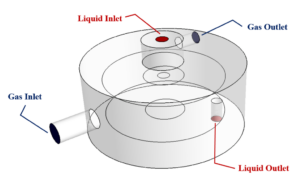
Water then enters through a vertical pipe from the top of the chamber and exits through a bottom pipe located at the bottom of the chamber; While airflow enters from a horizontal tube on the lateral surface of the chamber and exits through a horizontal tube on the lateral surface of the upper part.
The inlet air to the chamber has a mass flow rate of 0.001 kg.s-1 and the inlet water flow to the chamber has a mass flow rate of 0.1 kg.s-1.
Naturally, the water flow is located in the lower part of the chamber due to being denser and the airflow is located on the top of the water surface. Since there are two phases in this modeling, the multiphase model should be used.
For this reason, the VOF multiphase model is used in this modeling; So the primary phase is defined as water flow and the secondary phase is defined as airflow. Assuming that the water flow in the airflow is formed as a layer or free surface and does not mix with the airflow, the VOF model is the most appropriate model to define the present multiphase flow.
Also, the effect of surface tension between the two phases is defined and the amount of surface tension between the two phases of the water and air is defined as 0.072 N.m-1.
Separator Geometry & Mesh
The present model is designed in three dimensions using Design Modeler software. The model consists of a cylindrical chamber that has two inlet and outlet pipes for water flow vertically and two inlet and outlet pipes for air horizontally.
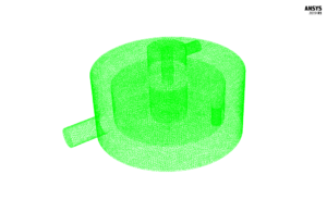
We carry out the model’s meshing using ANSYS Meshing software, and the mesh type is unstructured. The element number is 972786. The following figure shows the mesh.
Separator CFD Simulation
We consider several assumptions to simulate the present model:
- We perform a pressure-based solver.
- The simulation is steady.
- The gravity effect on the fluid is equal to -9.81 m.s-2 along the vertical axis.
The following table represents a summary of the defining steps of the problem and its solution:
| Models | ||
| Viscous | k-epsilon | |
| k-epsilon model | standard | |
| near wall treatment | standard wall functions | |
| Multiphase Model | VOF | |
| number of eulerian phases | 2 (water & air) | |
| formulation | implicit | |
| interface modeling | dispersed | |
| Boundary conditions | ||
| Inlet – Gas | Mass Flow Inlet | |
| mass flow rate – water | 0 kg.s-1 | |
| mass flow rate – air | 0.001 kg.s-1 | |
| Inlet – Liquid | Mass Flow Inlet | |
| mass flow rate – water | 0.1 kg.s-1 | |
| mass flow rate – air | 0 kg.s-1 | |
| Outlet – Gas | Pressure Outlet | |
| gauge pressure | 0 pascal | |
| Outlet – Liquid | Pressure Outlet | |
| gauge pressure | 0 pascal | |
| Walls | Wall | |
| wall motion | stationary wall | |
| Methods | ||
| Pressure-Velocity Coupling | Coupled | |
| Pressure | PRESTO | |
| momentum | first order upwind | |
| turbulent kinetic energy | first order upwind | |
| turbulent dissipation rate | first order upwind | |
| volume fraction | first order upwind | |
| Initialization | ||
| Initialization methods | Standard | |
| gauge pressure | 0 Pascal | |
| velocity (x,y,z) | 0 m.s-1 | |
| air volume fraction | 0 | |
| water volume fraction | 1 | |
Results & Discussions
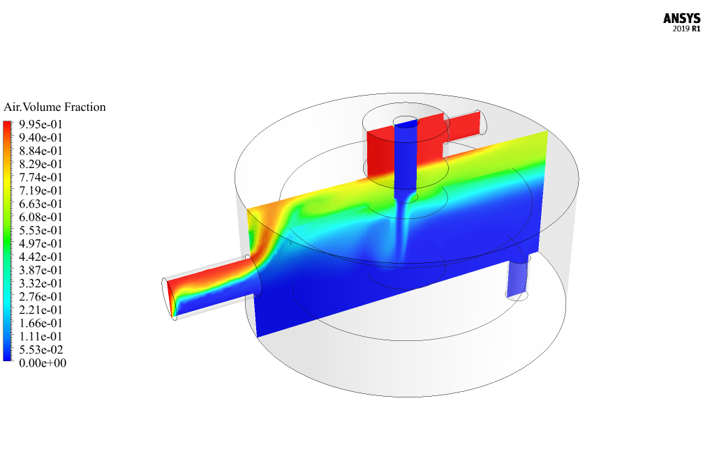
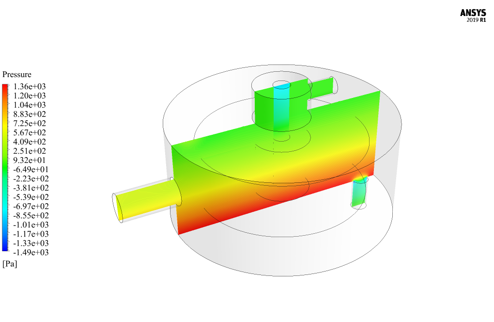
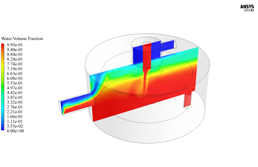
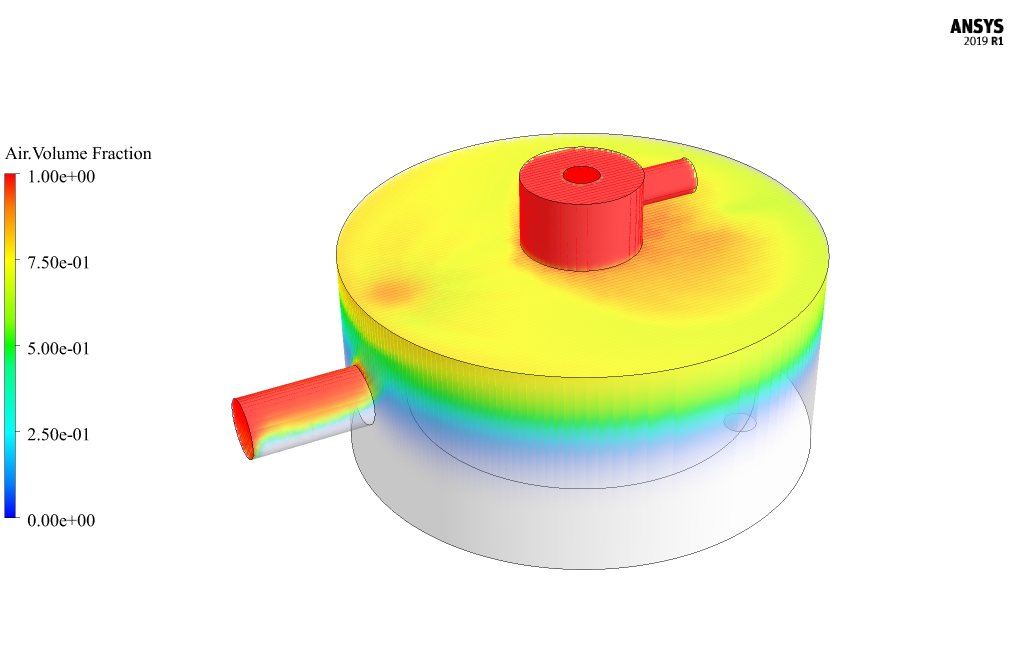
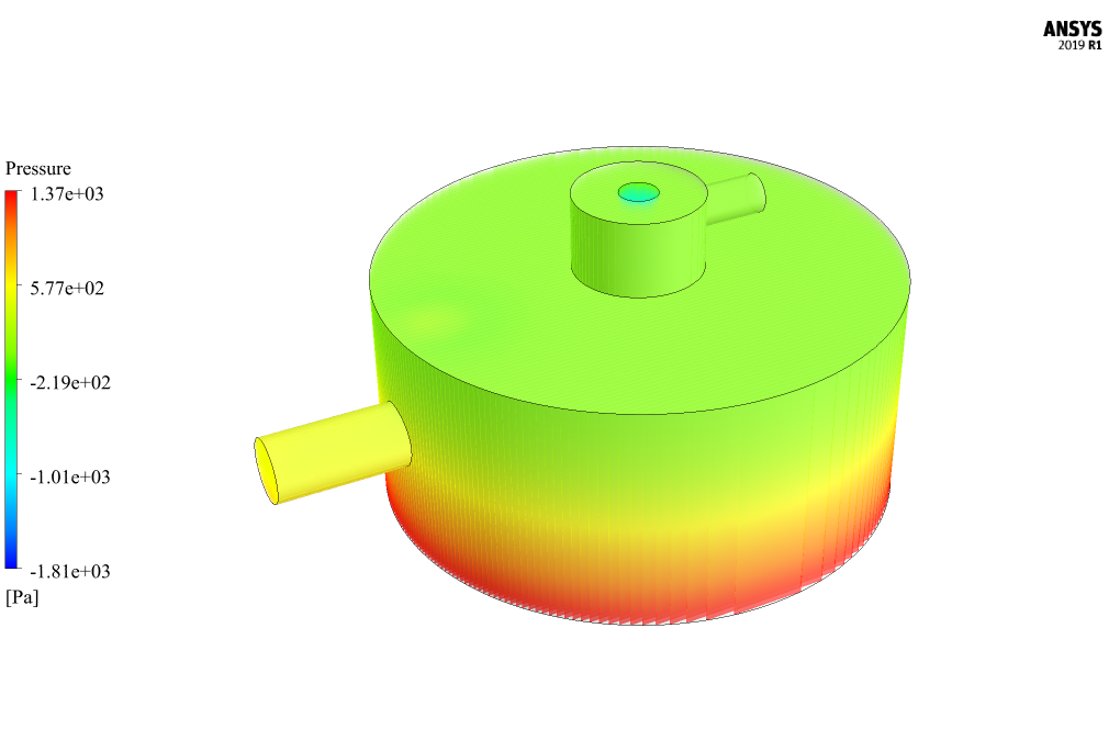
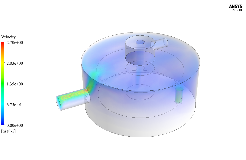
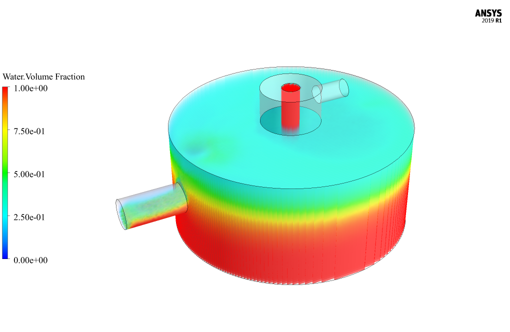
At the end of the solution process, two-dimensional and three-dimensional contours related to the mixing pressure and mixing velocity and volume fraction of each of the water and air phases are obtained. The images show that the airflow moves upwards because it is lighter and the water flow moves downwards because it is denser.



Adah Reichert –
Can the simulation be adjusted to handle different types of gases and liquids?
MR CFD Support –
Absolutely! The simulation can be adapted to handle different fluids by changing the properties of the fluids in the simulation setup. This makes it a versatile tool for various applications.
Tristin Dare –
How accurate is the CFD simulation?
MR CFD Support –
The accuracy of the CFD simulation depends on the quality of the input data and the complexity of the model. However, our simulations are designed to be as accurate as possible, using high-quality meshing techniques and robust numerical methods.
Yasmeen Rath –
I’m curious about how the separator chamber works in handling two-phase flow. Could you provide some insight into this?
MR CFD Support –
The Separator Chamber in this CFD simulation is designed to handle two-phase flow effectively. It separates the liquid and gas phases using their different densities. The fluids enter the chamber, where due to the change in velocity and direction, the heavier phase (usually the liquid) is forced to the walls of the chamber and drops down, while the lighter phase (gas) rises and exits from the top.
Candace D’Amore –
What are the benefits of using CFD simulation for a separator chamber?
MR CFD Support –
CFD simulation allows for the detailed analysis of the separator chamber’s performance under various conditions. It provides valuable data on pressure, velocity, and volume fraction of each phase in different parts of the chamber. This can guide the design process, leading to optimized performance and efficiency.