
Shock Tube CFD Simulation, ANSYS Fluent
$100.00 $10.00 Internship
- In this project, moving shock and expansion waves in a shock tube were simulated using ANSYS Fluent.
- The interactions of shock and expansion waves, as well as the reflection of waves at the end wall, were investigated, and the x-t wave diagram for the modeled shock tube was plotted.
- The geometry was created in SpaceClaim, and a mesh consisting of 300,000 elements was generated using ANSYS Meshing.
- The turbulence model is defined as Inviscid.
To Order Your Project or benefit from a CFD consultation, contact our experts via email (info@mr-cfd.com), online support tab, or WhatsApp at +44 7443 197273.
There are some Free Products to check our service quality.
If you want the training video in another language instead of English, ask it via info@mr-cfd.com after you buy the product.
Description
Description
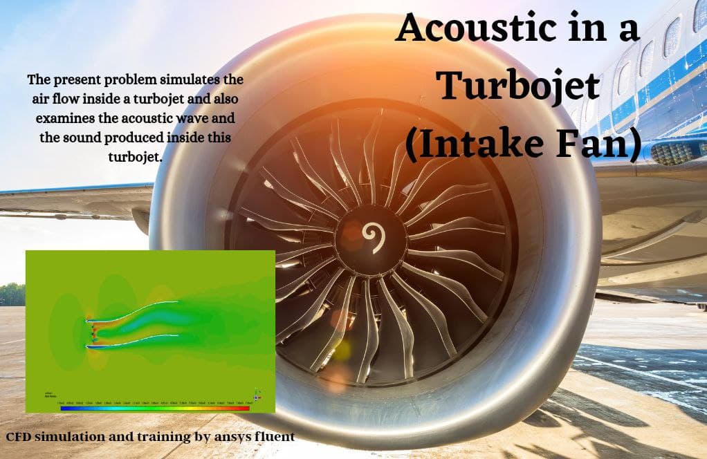
A shock tube is an instrument that makes it possible to study aerodynamic flow under a wide range of temperatures and pressures, as well as wave interactions, such as shock waves and expansion waves. It is sometimes also used to investigate 1D detonation of fuel-air mixtures or to generate the needed high pressure for wind tunnel experiments.
A shock tube consists of two sections: a high-pressure section known as the driver section and a low-pressure section called the driven section, which are separated from each other by a diaphragm. At t=0, the diaphragm ruptures, and the pressure difference causes shock waves and an expansion fan to form. These waves reflect off the walls and interact with each other.
In this simulation, a 2D shock tube with a driver length of 0.5 m and a driven section of 2.5 m is modeled. Initially, the driver pressure is specified at 1,000,000 Pa and the driven pressure at 100,000 Pa. The medium fluid is defined as air.
The geometry is designed in SpaceClaim® and is meshed using ANSYS Meshing®. The mesh is structured, and the element count is 300,000.
Methodology
Density-based solver has been selected, and the problem is defined as unsteady, which means the unsteady term in the conservation equations will also be discretized.
In this simulation, the energy equation has been activated. The viscous effects on the simulation are considered to be negligible, so the solution is valid away from walls where the velocity gradient is low, and viscous forces are very low. The turbulence model is defined as Inviscid. The air density is chosen to be computed with the ideal gas model.
Results
Contours of temperature and pressure are presented at two different times. Animations of pressure and temperature contours are extracted. From these animations, the movement of the shock wave, expansion fans, and contact regions are obvious. When the shock wave reaches the wall, it reflects off the wall, and the reflected shock has the same pressure ratio as the initial shock had. The expansion wave and contact region reflect at the end wall as well.
The x-t wave plot for this shock tube is generated and presented below.
You must be logged in to post a review.

Reviews
There are no reviews yet.