Shuffle Parking Ventilation CFD Simulation Training
$160.00 Student Discount
The present problem simulates the air conditioning inside the shuffle car park using ANSYS Fluent software.
Click on Add To Cart and obtain the Geometry file, Mesh file, and a Comprehensive ANSYS Fluent Training Video.To Order Your Project or benefit from a CFD consultation, contact our experts via email ([email protected]), online support tab, or WhatsApp at +44 7443 197273.
There are some Free Products to check our service quality.
If you want the training video in another language instead of English, ask it via [email protected] after you buy the product.
Description
Shuffle Parking Ventilation Project Description
The present problem simulates the air conditioning inside the shuffle car park using ANSYS Fluent software. In this project, a shuffle parking is designed entirely, with three floors, and eight cars are located on its floors. In this type of parking, cars are parked in such a way that they have to act in a jigsaw puzzle to enter and exit; In this way, the space of a car is empty, and the cars can be parked or taken out of the park by moving the puzzle horizontally or vertically.
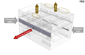
In this project, it is assumed that the carbon monoxide flow is emitted through the exhaust of the middle car from the second floor to the interior of the parking lot and pollutes its interior. This project aims to design a proper ventilation system to prevent the spread of pollutants and help eliminate these gases inside the parking. Therefore, several vents have been used on the roof of the parking.
Project Description
The species transport model has been used to simulate the process of carbon monoxide emission into the air inside the parking. So the number of gaseous species is equal to two, including air and carbon monoxide (CO). Therefore, the exhaust outlet is defined as the inlet boundary condition; So that the mass fraction of CO is equal to 1. A UDF is also used to define the mass flow rate of the emitted gas; Because depending on the time, the flow rate of carbon monoxide can be zero or have a variable value. For air vents in the ventilation system, a value of zero for the mass fraction of carbon monoxide is used. However, the inlet velocity condition is used to define the boundary condition of these outlet valves, but the velocity value is applied as a negative value.
Because the goal is to block the flow of polluted air inside the parking to be discharged out of the parking through these vents at a certain speed. To compare the performance of ventilation valves, the amount of suction power or the same amount of negatively defined velocity at these different output limits is considered; So that the speed value of the end valves of the parking has a value equal to -2. 5 m.s-1 and the value of the initial valves (above the car exhaust) has a value equal to -10 m.s-1.
Shuffle Parking Geometry & Mesh
The present model is designed in three dimensions using Design Modeler software. The current model is related to a multi-story parking of the shuffle parking type with a simple building, inside which eight cars are designed. A boundary on the exhaust port of the middle vehicle is defined as the source of carbon monoxide emission, and several boundaries are defined as panels or vents for the exit of polluted air on the roof of the parking lot.
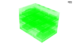
We carry out the model’s meshing using ANSYS Meshing software. The mesh type is unstructured. The element number is 1467439. The following figure shows the mesh.
CFD Simulation
We consider several assumptions to simulate the present model:
- We perform a pressure-based solver.
- The simulation is unsteady.
- The gravity effect on the fluid is ignored.
The following table represents a summary of the defining steps of the problem and its solution:
| Models | ||
| Viscous | k-epsilon | |
| k-epsilon model | RNG | |
| near-wall treatment | standard wall function | |
| Species Model | Species Transport | |
| number of volumetric species | 2 (air & CO) | |
| Energy | On | |
| Boundary conditions | ||
| Inlet (car exhaust) | Mass Flow Inlet | |
| mass flow rate | UDF | |
| temperature | 300 K | |
| CO mass fraction | 1 | |
| Inlet (filter plate on the back & in front of cars) | Pressure Inlet | |
| gauge total pressure | 0 Pascal | |
| temperature | 300 K | |
| CO mass fraction | 0 | |
| Outlet (vent panels) | Velocity Inlet | |
| velocity magnitude | -10 or -2.5 m.s-1 | |
| temperature | 300 K | |
| CO mass fraction | 0 | |
| Internal Walls | Wall | |
| wall motion | stationary wall | |
| thermal condition | coupled | |
| External Walls | Wall | |
| wall motion | stationary wall | |
| heat flux | 0 W.m-2 | |
| Methods | ||
| Pressure-Velocity Coupling | Coupled | |
| pressure | second order | |
| momentum | first order upwind | |
| turbulent kinetic energy | first order upwind | |
| energy dissipation rate | first order upwind | |
| CO | second order upwind | |
| energy | second order upwind | |
| Initialization | ||
| Initialization methods | Standard | |
| gauge pressure | 0 Pascal | |
| velocity (x,y,z) | 0 m.s-1 | |
| CO mass fraction | 0 | |
| temperature | 300 K | |
Results
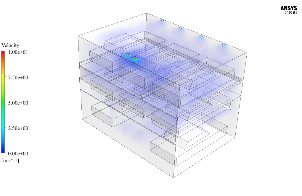
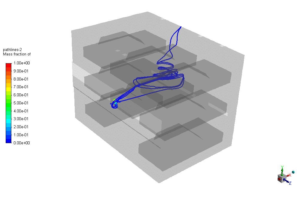
At the end of the simulation process, the pathline of the carbon monoxide exhaust from the exhaust port of the vehicle is displayed. In the mentioned ventilation system, several air intake vents have been used on the roof of the parking lot to eliminate environmental pollution. There are four panels for air exit at the end side and two panels for air exit at the front side of the parking. Also, the fresh air entering this ventilation system is supplied from the filter plate on the parking wall behind the cars on the middle floor and the front panel of the cars on the lower floor. Although the suction power of the end panels of the roof (-2.5 ms-1) is less than the suction power of the front panels (-10 ms-1), the gas flow after scattering inside the parking from the same end panels Suction to the outside environment.
Analysis
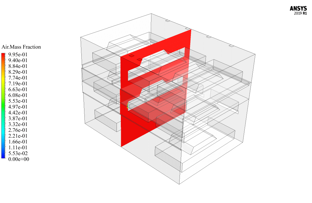
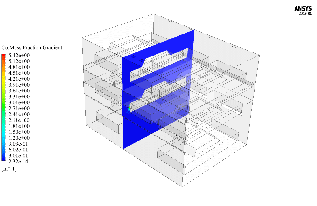
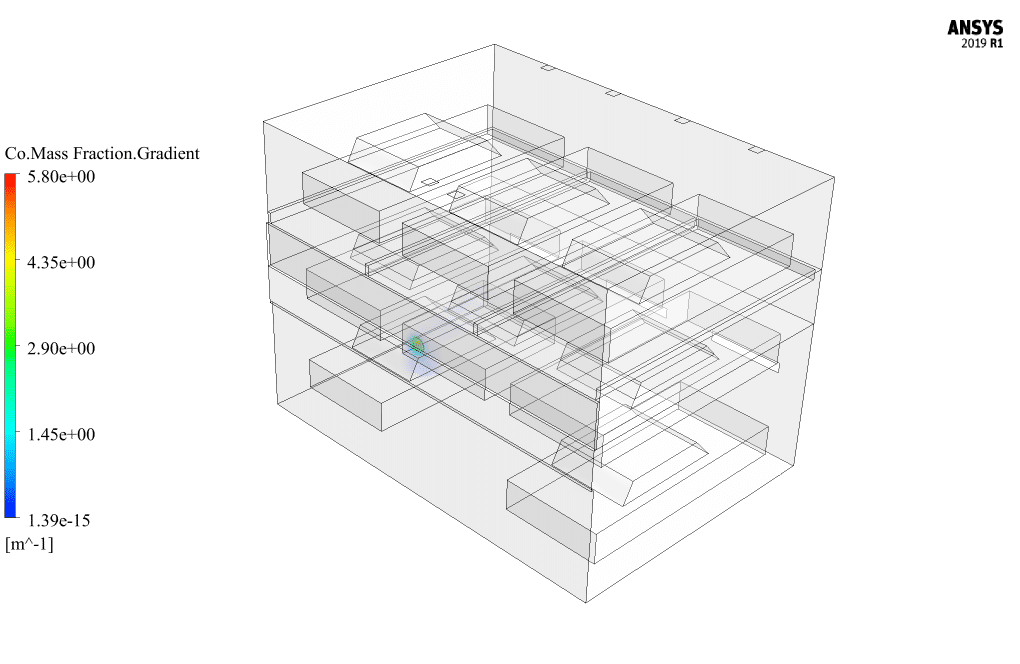
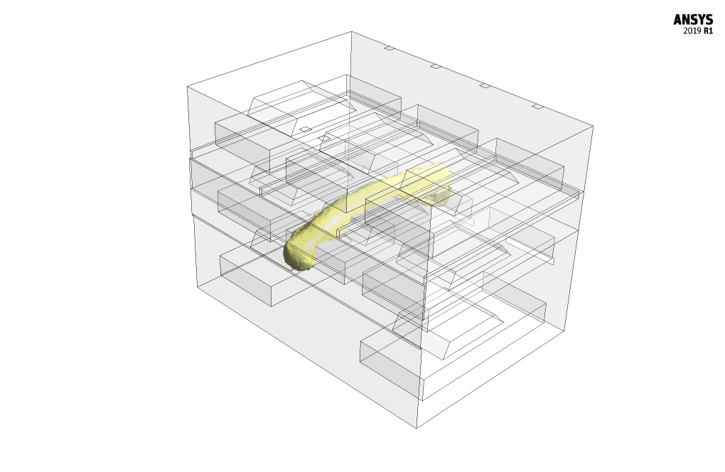
This is because the air pressure entering the parking lot in the rear wall of the cars on the middle floor prevents the direct exit of carbon monoxide gas from the exhaust to the exhaust valve located on top of it. Next, two-dimensional and three-dimensional contours related to velocity, mass fraction of carbon monoxide, mass fraction of air, and gradient mass fraction of carbon monoxide are obtained. Also, using the iso-surface command, a layer of CO gas with a mass fraction of 0.001 is formed to show how the gas is released into the environment in the form of a graphic effect. In general, these contours show well that the carbon monoxide gas emitted from the exhaust port of the vehicle quickly disappears into the interior of the parking. Therefore, the desired ventilation system works well and prevents the significant spread of gas inside the parking.
We obtain all results, including flow path lines and contours, at 5400 seconds.


Raegan Ryan –
This training module seems very thorough! I was particularly impressed by the detailed setup, especially the use of different suction powers for the vents. Great job on explaining the simulation process and the boundary conditions applied.
MR CFD Support –
Thank you so much for your kind words and positive feedback! We’re really pleased to hear you found the training so detailed and thorough. Our team strives to provide comprehensive educational materials, and it’s rewarding to learn when they are well received. If you have any further questions or need additional assistance, we’re always here to help!
Prof. Dustin Mueller MD –
The project seems well-thought-out with precise considerations on how to deal with potential pollutants in the parking area. Great job on leveraging CFD to ensure safety and comfort!
MR CFD Support –
Thank you for your positive feedback! We’re glad to hear that you appreciate the intricate details and the thorough approach used in simulating the shuffle parking ventilation system. Ensuring safety and environmental standards is a top priority for us, and it’s wonderful to know that we met your expectations. If you have further inquiries or need assistance with similar projects, don’t hesitate to reach out.
Felicity Carter –
The simulation training was comprehensive and insightful. The clear step-by-step instructions and detailed boundary conditions provided an effective understanding of ventilating a shuffle car park. Most impressive was the use of UDF for the dynamic emission rates of CO, which paralleled realistic conditions very effectively.
MR CFD Support –
Thank you for your valuable feedback! We’re glad the training provided you with a comprehensive and understandable approach to the complex ventilation simulation in a parking structure. We always strive to offer practical insights for realistic situations using industry-standard tools like ANSYS Fluent. If you have any further inquiries or need additional assistance, feel free to reach out.
Mr. Ross McGlynn –
I’m impressed by the detailed workflow of the CFD simulation for shuffle parking ventilation. The use of specific inlet and outlet velocity points seems crucial for optimizing airflow. The successful dissipation of carbon monoxide using the vents is reassuring. Great job on addressing a significant health and safety concern with such thorough simulation studies.
MR CFD Support –
Thank you for acknowledging our CFD simulation process for proper ventilation in shuffle parking. We’re delighted to hear that our efforts in providing a safe and efficient solution for air quality management have met with your satisfaction. Your appreciation is a testament to the quality and dedication we invest in our simulations. Should you have any more queries or require further insights on any of our products, please feel free to reach out.
Josephine Walker –
I’m impressed with the detailed simulation of carbon monoxide dispersion in the shuffle parking ventilation project. Great work at demonstrating how various ventilation strategies can impact air quality within a multi-story car park!
MR CFD Support –
Thank you for your kind words and for recognizing the detail in our simulation work! We’re delighted to hear that you found the demonstration informative and useful for understanding the effectiveness of ventilation strategies in managing air quality in complex structures like multi-story car parks.
Sonny Ratke –
How effective is the provided ventilation set-up in managing the spread of carbon monoxide at different areas of the parking lot?
MR CFD Support –
The presented ventilation set-up, with its strategically placed vents, has performed efficiently in managing pollutants. The speed and placement of the vents help to swiftly extract carbon monoxide emissions, minimizing the spread throughout the parking lot. All areas, regardless of proximity to emission sources, evidence efficient contaminant removal and safety maintenance.
Lincoln Okuneva –
The training materials explained Shuffle Parking Ventilation vividly. The use of visuals and diagrams really helped in understanding the flow patterns and how gas is vented out. Kudos to the team for such an engaging and detailed explanation.
MR CFD Support –
Thank you for your kind words! We’re thrilled to hear that you found the training materials engaging and informative. Visualization is a key aspect of understanding complex simulations like Shuffle Parking Ventilation, and we’re glad it enhanced your learning experience.
Kraig Schmitt I –
The simulation was so insightful! The attention to detail in preventing carbon monoxide spread with the proposed ventilation design was fantastic, and it’s great to see the function of each vent so clearly broken down.
MR CFD Support –
Thank you for your positive feedback! We are glad that our detailed analysis and design of the shuffle parking ventilation system were helpful and insightful. It’s our goal to provide clear and useful simulations that can be applied to ensure safety and functionality. We appreciate your acknowledgment of our attention to detail.
Mrs. Emie Mraz –
The real-time operation of a shuffle parking can be quite complex, with cars moving in and out. How does this dynamic movement affect the ventilation simulation, and was this factor included in the CFD simulation?
MR CFD Support –
In the ventilation simulation, the dynamic car movement commonly seen in a shuffle parking system is not explicitly modeled. Instead, the focus is on steady-state conditions to determine if the ventilation system can adequately remove pollutants like carbon monoxide during operation. Factors such as emissions from car exhausts are modeled, but the physical movement of the cars is not directly simulated.
Nash Wunsch –
The training materials for the shuffle parking ventilation simulation were immaculate. Breaking down complex CFD concepts into digestible lessons made learning efficient and enjoyable. The use of hands-on examples for creating boundary conditions and implementing the species transport model was illuminating. Hats off to the clear diagrams and meticulous explanation of UDF programming, which greatly demystified mass flow rate adjustments over time. Moreover, the comparative analysis of different vent velocities demonstrated practical application of core principles, rendering insights into engineering reliable ventilation systems in closed partitions like parking garages. This has solidified my understanding of air quality control measures in urban infrastructure design. Brilliant work!
MR CFD Support –
Thank you for your heartfelt review! We are thrilled to hear that our training material exceeded your expectations. It is our goal to provide comprehensive learning experiences that are both informative and practically applicable. Your understanding and insights affirm our commitment to a high-quality educational process. We truly appreciate the time you took to acknowledge the impact of our materials on your learning journey. Should you have any further inquiries or need more information in the future, don’t hesitate to reach out. Thank you once again for choosing us to guide you through the complexities of CFD simulation!
Jerel VonRueden DVM –
I felt that the training for Shuffle Parking Ventilation CFD Simulation was comprehensive and well-designed. The step-by-step approach assisted me in understanding how to model and analyze a complex ventilation system. The use of different strategies for the placement and velocity of vents was particularly instructive, showing how these factors affect the distribution and removal of pollutants like carbon monoxide.
MR CFD Support –
We greatly appreciate your positive feedback on the Shuffle Parking Ventilation CFD Simulation training. It’s wonderful to hear that the course’s structure and content were instrumental in enhancing your understanding of ventilation systems in complex environments. Thank you for recognizing the effort placed into showcasing the impacts of strategic vent placement and velocity. Your insights are valuable to us!
Ms. Bridie Gibson –
The Shuffle Parking Ventilation training seems incredibly detailed. Wonderful visuals and thorough explanations make complex concepts much easier to understand. The use of a UDF to simulate varying CO emission rates was particularly helpful for a realistic simulation!
MR CFD Support –
Thank you for highlighting the aspects you found helpful in the Shuffle Parking Ventilation training. Our focus is on providing detailed and realistic simulations to enhance understanding. We’re glad to know that our efforts resonate well with our learners. Your satisfaction is our priority!
Mr. Jerrod Barrows I –
What a comprehensive simulation! The attention to complex scenarios like the CO emission in the shuffle parking was impressive. The use of species transport for CO and air ensures a realistic study of the flow of pollutants, and the implementation of varied suction powers for different vents shows a deep understanding of the ventilation needs in different sections of the parking lot. Having the results at a well-proven time of 5400 seconds provides assurance about the equilibrium state of the flow. Kudos to the team for tackling such an intricate project with detailed modeling and ventilation strategy!
MR CFD Support –
Thank you for taking the time to provide us with such positive feedback! We are thrilled to hear that our thorough approach and attention to detail in simulating the Shuffle Parking Ventilation scenario met with your approval. Your recognition of the comprehensive study on pollutant dispersion and custom ventilation solutions means a lot to us. It’s fantastic to know that the end results at 5400 seconds provided the necessary assurance. Your appreciation greatly motivates our team to continue delivering high-quality CFD simulations. Thank you again for your kind words!