
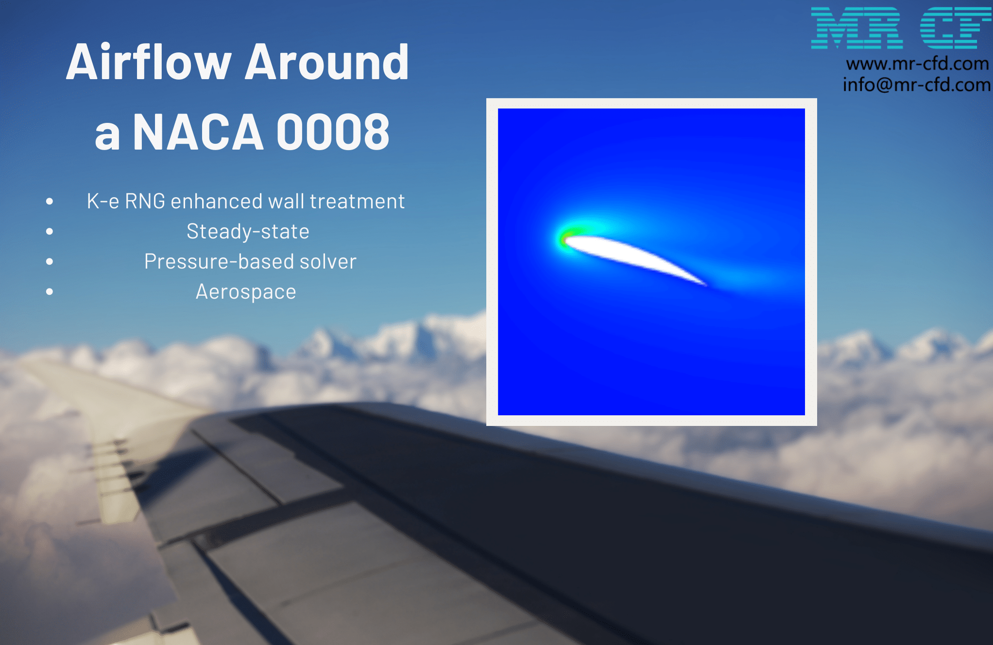
Water Discharge of a Rotating Tank, Ansys Fluent CFD Simulation Training
$80.00 Internship
In this project, the water discharging of a rotating tank has been simulated, and the results have been investigated.
Click on Add To Cart and obtain the Geometry file, Mesh file, and a Comprehensive ANSYS Fluent Training Video.To Order Your Project or benefit from a CFD consultation, contact our experts via email (info@mr-cfd.com), online support tab, or WhatsApp at +44 7443 197273.
There are some Free Products to check our service quality.
If you want the training video in another language instead of English, ask it via info@mr-cfd.com after you buy the product.
Description
Water Discharge Project Description
In this project, Ansys Fluent software has been used to simulate the water discharge of a rotating tank. The Volume of Fluid (VOF) model has been used to simulate and solve the two-phase flow field equations. The primary phase is air and, the secondary phase is water. The tank rotates about the Y-Axis at a speed of 80 rev/min. In the bottom of the tank, there are two circular orifices that water discharges from them.
Geometry & Mesh
The geometry of the present model is generated using Design Modeler software. The tank is a cylinder with a diameter of 1 m and a height of 0.75m, and the orifice diameter is 150 mm.

The meshing of the present model has been done using ANSYS Meshing software. The mesh type is unstructured in all of the computational domains, and the element number is equal to 470,369.

The boundary conditions are shown in the figure below.

Water Discharge CFD Simulation Settings:
We consider several assumptions to simulate the present model:
- Due to the incompressibility of the flow, the pressure-based solver method has been selected.
- The simulation is transient.
- The gravity effect is considered equal to -9.81 m.s-2 on Y-axis.
- The rotational speed is deemed to be 80 rpm on Y-axis for the tank wall.
The K-epsilon standard viscous model with a Scalable wall function has solved the turbulent flow equations. The pressure-velocity coupling scheme is SIMPLE. The second-order upwind discretization method has been used for Momentum, and The first-order upwind discretization method has been used for Turbulent kinetic energy and Turbulent dissipation rate.
The following table represents a summary of the defining steps of the problem in this project and its solution:
| General | ||
| Solver | Type | Pressure-based |
| Time | Transient | |
| Gravity | X | 0 |
| Y | -9.81 [m/s^2] | |
| Z | 0 | |
| Models | ||
| Multiphase | ||
| Model | Volume of Fluid | |
| Number of Eulerian phases | 2(air & water) | |
| Interface modeling | Sharp | |
| Formulation | Explicit | |
| Primary phase | air | |
| Secondary phase | water | |
| Viscous | ||
| k-epsilon | Standard | |
| Near wall treatment | Scalable wall functions | |
| Material Properties | ||
| Air | ||
| Density | 1.225 | |
| viscosity | 1.7894e-05 | |
| water-liquid | ||
| Density | 998.2 | |
| viscosity | 0.001003 | |
| Boundary conditions | ||
| Outlet | Pressure outlet | |
| Orifice | Pressure outlet | |
| wall | Moving wall | |
| speed | 80 [rev/min] | |
| Rotation axis direction | x=0,y=1,z=0 | |
| Rotation axis origin | x=0,y=0,z=0 [m] | |
| Methods | ||
| Pressure-Velocity Coupling | SIMPLE | |
| Pressure | PRESTO | |
| Momentum | Second-order upwind | |
| Turbulent kinetic energy | first-order upwind | |
| Turbulent dissipation rate | first-order upwind | |
| Volume fraction | Compressive | |
| Adaption Controls | ||
| Cell registers | Region_0 | |
| Type | Cylinder | |
| Radius | 0.5 | |
| X-Axis [min] | 0 | |
| X-Axis[max] | 0 | |
| Y- Axis [min] | 0 | |
| Y- Axis [max] | 0.6 | |
| Z- Axis [min] | 0 | |
| Z- Axis [max] | 0 | |
| Initialization | ||
| Initialization methods | Standard | |
| Patch | Phase | water |
| Variable | Volume Fraction | |
| Zones to patch | Region_0 | |
| Value | 1 | |
| Run calculation | ||
| Time step size | 0.02 | |
| Max iterations/time step | 20 | |
| Number of time steps | 700 | |
Results
After the solution process is completed, contours of Pressure, Water volume fraction, Eddy viscosity, and Streamline are extracted. As can be observed, under the influence of gravity and the rotational speed of the tank, the water inside the cylinder tank rotates about the y-axis as it exits the orifice.
[/vc_column_text]You must be logged in to post a review.
Reviews
There are no reviews yet.