Wind Turbine Considering Turbine Base 3-D Simulation
$160.00 Student Discount
- The problem numerically simulates a horizontal axis wind turbine using ANSYS Fluent software.
- We design the 3-D model with the Design Modeler software.
- We Mesh the model by ANSYS Meshing software, and the element number equals 1981472.
- We use the Frame Motion (MRF) to define a rotational movement.
To Order Your Project or benefit from a CFD consultation, contact our experts via email ([email protected]), online support tab, or WhatsApp at +44 7443 197273.
There are some Free Products to check our service quality.
If you want the training video in another language instead of English, ask it via [email protected] after you buy the product.
Description
Wind Turbine (3-D) Considering Turbine Base, ANSYS Fluent Simulation Training
This project will study an incompressible isothermal airflow close to a standard horizontal axis wind turbine considering its base using ANSYS Fluent software.
Standard Horizontal Axis Wind Turbine (HAWT) is becoming increasingly important in wind power generation. Fortunately, it is known that HAWTs have higher efficiency compared to VAWTs.
Thus, they have been employed in open fields and can produce energy from the wind. We carry out the model’s meshing using ANSYS Meshing software. The element number is 1981472.
Wind Turbine Methodology
This project will study an incompressible isothermal airflow close to a standard horizontal-axis wind turbine. The geometry is a wind turbine with a 30-meter base inside a 300-meter wind tunnel.
Also, we select the maximum speed of 1 m/s for the wind. Furthermore, the frame motion technique is exploited to model the HAWT blades rotating motion, and the rotating turbine velocity is set to 30 RPM.
Moreover, the SST k-omega model is used to solve turbulent fluid equations due to its advantage in predicting flow patterns near and far from the blades’ surfaces.
Wind Turbine Conclusion
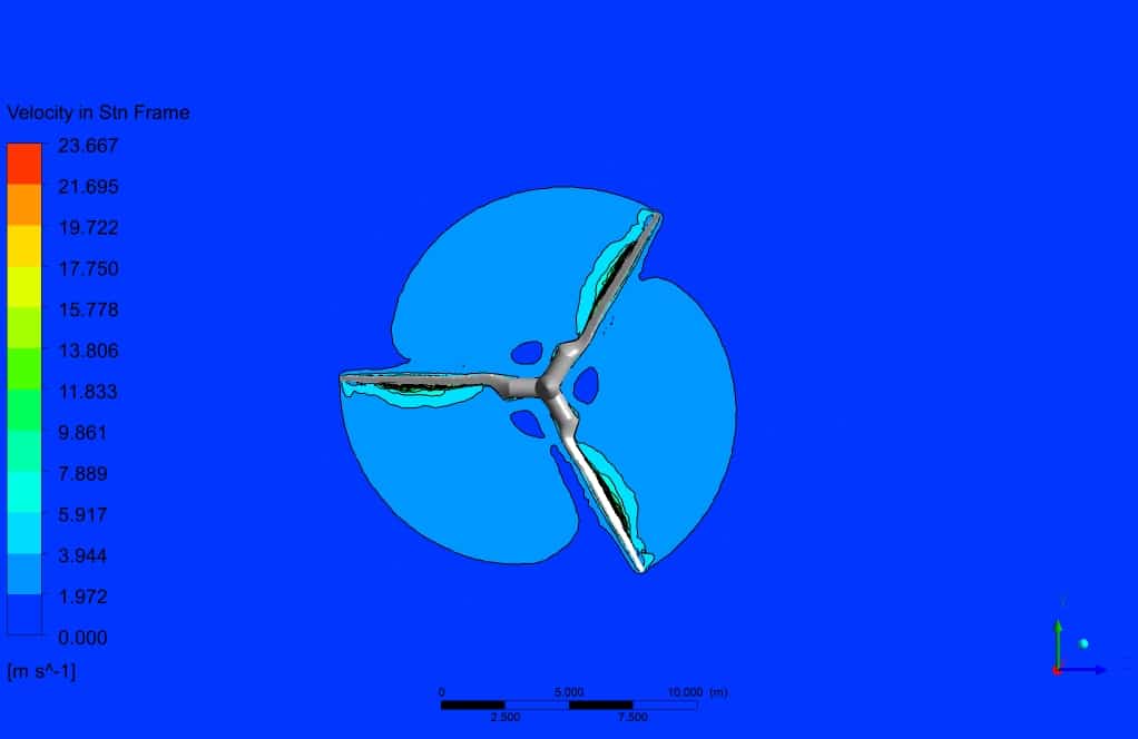
After the solution process, two-dimensional contours related to the velocity and pressure are obtained. The leading edge of the turbine wall corresponded to the lowest pressure, which is logical since the velocity has the highest value on the tip of the blade.
We depicted both contours and streamlines for the velocity field to get much insight into the problem. Briefly, the velocity field adjacent to the wall of the turbine has the highest gradient.
Additionally, the streamlines illustrate the quality of the flow streams resolved in the wake section, which is the core challenge of aerodynamic simulation. Finally, we have found that the drag force is 1.067 (kN), which was accurate for a wind turbine with a 30-meter base with the noted specifications.


Loraine Abbott –
The demonstration of airflow changes near the turbine blades was really insightful. Great job on effectively illustrating the wake effects behind the turbine as well!
MR CFD Support –
Thank you for your positive feedback! We are thrilled to hear that you found the insights into the airflow and wake effects informative and helpful. Understanding these aerodynamic phenomena is crucial for improving wind turbine design and efficiency, and we’re glad our simulation training could effectively illustrate these concepts for you. We appreciate your support and hope you continue to find our products beneficial.
Gilda Kuphal –
Feedback: As an enthusiast in renewable energy and CFD applications, I was particularly impressed with the training provided on the Wind Turbine (3-D) Considering Turbine Base using ANSYS Fluent. The thorough approach to simulate the effect of the wind and the detailed analysis of the complex flow patterns around the turbine, including its base, acts as a significant learning tool. Additionally, the use of the SST k-omega model for better flow prediction near the blade surfaces not only benefited my understanding of the aerodynamic phenomena but also the practical application of CFD in enhancing turbine design. A job well done by the MR CFD training team!
MR CFD Support –
We are delighted to hear you found the wind turbine simulation training to be a rich learning experience and a worthwhile resource for your interests in renewable energy. Your compliments are greatly appreciated, and we’re greeted with immense satisfaction pertaining to your enhanced understanding of aerodynamic simulations as applied to wind turbines. Should you have any further insights or questions, our team is always on standby to provide assistance. Thank you for your kind review!
Hugh Hane DVM –
The project is exceptional! Well done on simulating the wind turbine accurately. Seeing the detailed results gives a substantial understanding of the fluid dynamics around such structures.
MR CFD Support –
Thank you for your positive feedback and complimenting the thoroughness of the wind turbine simulation project using ANSYS Fluent. We’re glad to hear that it provided a valuable insight into the fluid dynamics involved in wind energy generation. If you need further information or assistance with similar simulations, feel free to reach out!
Evalyn Jacobi –
I admire how the SST k-omega model is utilised in the project to accurately predict fluid flow near and far from the blade surfaces. The level of detail in the simulation results is impressive, particularly the insights provided by the velocity field contour and streamlines.
MR CFD Support –
Thank you for your positive feedback! We are glad to hear that our use of the SST k-omega model to predict fluid flow around the wind turbine blades met your expectations and was satisfactory. Our goal is to provide detailed and accurate simulations to ensure great insights and we’re pleased to note that the results provided you with the understanding you needed.
Benjamin Considine II –
Fabulous simulations and fluid dynamics! The complexity of predicting a realistic aerodynamic response in this setup must have been challenging, but the review makes it clear that the HAWT model was well executed and offers valuable insights. Keep up the excellent work!
MR CFD Support –
Thank you for your positive feedback! We’re delighted to hear that you’ve recognized the complexities involved in aerodynamic simulation and are satisfied with the results of our wind turbine simulation project. If you have any more questions or need further assistance, don’t hesitate to reach out.
Donato Sanford –
Tremendous learning tool! Could feel the blade speed just by wading through the explanation—got me utterly captivated by the rotation dynamics and airflow models. Bravo on fleshing out every technical nuance so meticulously.
MR CFD Support –
Thank you for your wonderful feedback! It is fantastic to hear that you found our training on wind turbine simulation so engaging and informative. We strive to deliver detailed and thorough education on complex CFD topics. Keep an eye out for our upcoming products, and happy learning!
Tara Paucek DDS –
The project description was highly informative, and it mentioned the drag force outcome. Could you tell me what forces, besides drag, were analyzed, and how they impact the wind turbine performance?
MR CFD Support –
In a wind turbine simulation, besides aerodynamic drag, the lift force on the blades is also crucial as it contributes to the rotational torque that generates power. Additionally, effects such as blade bending moments and stresses may be examined to understand structural integrity. All these forces together impact efficiency, durability, and performance of the wind turbine. Specific details on each of these factors and their particular impacts would be obtained during a comprehensive analysis of the simulation results in ANSYS Fluent.
Deshaun Bailey PhD –
I found the explanation of airflow contour results very insightful for understanding wind turbine efficiency. Thank you for the meticulous analysis!
MR CFD Support –
Thank you for your kind words! We’re thrilled to know that our analysis on airflow contours provided you with clear insights into the efficiency of wind turbines. We are committed to delivering comprehensive and informative simulations. If you have any more questions or need further clarity on any aspect, please feel free to reach out.
Dagmar Runolfsson –
I love how detailed the description of the wind turbine simulation is! The inclusion of RPM and specific mention of the SST k-omega model really helps understand how the simulation is configured to achieve realistic results. Great job on clearly explaining the setup and the results obtained, especially the challenge of aerodynamics in the wake section.
MR CFD Support –
Thank you for your kind words! We’re thrilled to hear that you found the description of the wind turbine simulation detailed and helpful. Our goal is always to provide clear and comprehensive information to aid understanding of the setup and results of our simulations. We appreciate your feedback and are glad that the efforts to address aerodynamic challenges in the wake section notably contributed to a greater insight into the problem.
Ms. Maud Goodwin –
I was impressed by the clarity of the results, especially the streamlines in the wake section. It’s great to see the gradient near the turbine wall captured so well.
MR CFD Support –
Thank you for your positive feedback! We’re glad to hear that our simulation results met your expectations, providing clear visualization and detailed analysis of the airflow around the wind turbine.
Theo Schuster III –
The training course seems detailed, but does it provide information about how to set up and evaluate the performance parameters of the wind turbine like its power output or efficiency?
MR CFD Support –
In this training, you will learn how to apply boundaries and initial conditions related to wind turbine operation within ANSYS Fluent. You will gain insights into setting up and interpreting the drag forces, which are closely related to the turbine’s aerodynamic efficiency. To evaluate power output or overall efficiency, you would typically use the results from drag force calculations, along with torque and rotational speed, to determine mechanical power produced by the turbine. The course aims to ensure you have the fundamental understanding required to perform such analyses on horizontal-axis wind turbines.
Ruth Gutmann –
The project outlines the effective use of the SST k-omega model in simulating the airflow around wind turbine blades. The inclusion of a wind tunnel environment and the accounting for the drag force with high precision highlight the attention to detail and the application’s potential in practical engineering assessments.
MR CFD Support –
We appreciate your positive feedback on utilizing the SST k-omega model for our wind turbine simulation training. It’s rewarding to know that the detailed environment setup and accurate force measurements provided valuable insights. Thank you for recognizing the effort and quality of our CFD analysis.