Elbow Optimization with RBF Morph, CFD Simulation Ansys Fluent Training
$120.00 Student Discount
In this project, an elbow optimized with the RBF (Mesh Morphing) Method and the results of this simulation has been investigated.
Click on Add To Cart and obtain the Geometry file, Mesh file, and a Comprehensive ANSYS Fluent Training Video.To Order Your Project or benefit from a CFD consultation, contact our experts via email ([email protected]), online support tab, or WhatsApp at +44 7443 197273.
There are some Free Products to check our service quality.
If you want the training video in another language instead of English, ask it via [email protected] after you buy the product.
Description
Introduction to RBF Morph (Mesh Morphing)
Today, geometry optimization methods have been greatly developed to achieve better performance in mechanical devices. One of these methods is mesh morphing (RBF). Mesh morphing is a method of reshaping the lattice surface while preserving the topology. This method defines a displacement field on a cloud of origin points and then propagates it on a cloud of target points.
Project Description
In this project, the flow inside an elbow is first simulated by Ansys Fluent software. Then the geometry is optimized to achieve smaller pressure drops using the morphing mesh optimization method.
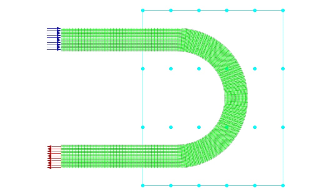
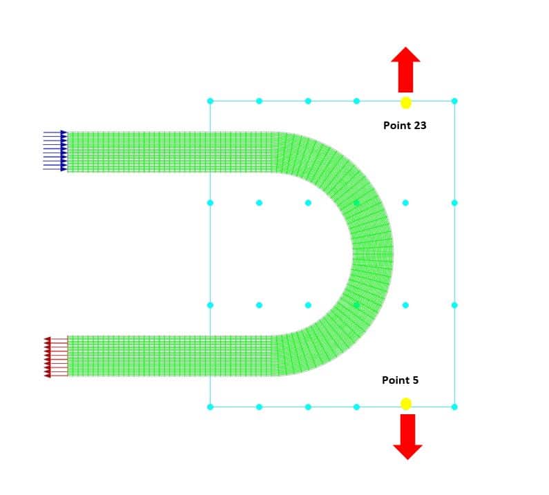
For this purpose, an area is defined around the elbow bend, the center of which is (-3,7.5) with the regular control point distribution. The update from the zone is set for the elbow walls and this walls constraint type is set to unconstrained type. The length of this rectangle is 12 meters and its height is 15 meters. The number of nodes in the X-direction is 6 and the number of nodes in the y-direction is 4. In fact, the input parameter for this optimization is the vertical displacement of these points.
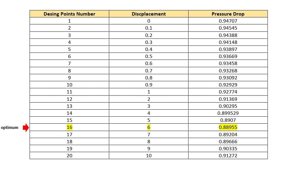
The constraints for other boundaries (Inlet and outlet) are set to fix. To begin the optimization process, you can define the motion for each of these points according to your engineering vision and physical understanding of the objective function. In this project, for point number 5, the displacement to the -y is considered and for point 23, the displacement to the +y is considered. Optimization has been done in 19 stages and for displacements of 0.1,0.2,0.3,0.4,0.5,0.6,0.7,0.8,0.9,1,2,3,4,5,6,7,8,9, and 10 meters for both points.
Geometry & Mesh
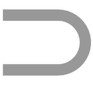
We designed this elbow in Design Modeler software. The length of the arms is 10 meters, the inner radius is 4 meters and the outer radius is 6 meters.
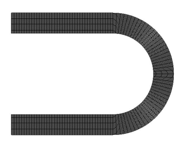
The meshing of this project has been done by Ansys Meshing software. The mesh type is fully structured and the element number is 3900.
Elbow CFD Simulation
We consider three assumptions for this simulation:
- we used the pressure-based solver due to the incompressibility.
- The gravity effect is ignored
- We performed this simulation in a steady state.
The following table represents a summary of the solution:
| Models(Viscous) | ||||
| Viscous | standard k-epsilon | standard wall function | ||
| Materials | ||||
| Fluid | Definition method | Fluent database | ||
| Material name | Water-liquid | |||
| Density | Constant =998.2 kg/m3 | |||
| Cell zone condition | ||||
| Material name | Water liquid | |||
| Boundary condition | ||||
| Inlet_flow | Type | Velocity inlet | ||
| Velocity magnitude normal to Boundary | 0.1 m/s | |||
| Outlet | Type | Pressure-outlet | ||
| Gauge pressure | 0 | |||
| Wall-elbow | Type | Stationary wall | ||
| Shear condition | No-slip condition | |||
| Solver configuration | ||||
| Pressure-velocity coupling | Scheme | SimpleC | ||
| Spatial Discretization | Gradient | Least squares cell-based | ||
| Pressure | Second-order | |||
| Momentum | Quick | |||
| Turbulent Kinetic Energy | First Order Upwind | |||
| Turbulent Dissipation Rate | First Order Upwind | |||
| Initialization | Initialization methods | Hybrid Initialization | ||
| Run calculation | Number of iterations | 1000 | ||
RBF Morph Results
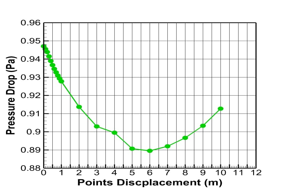
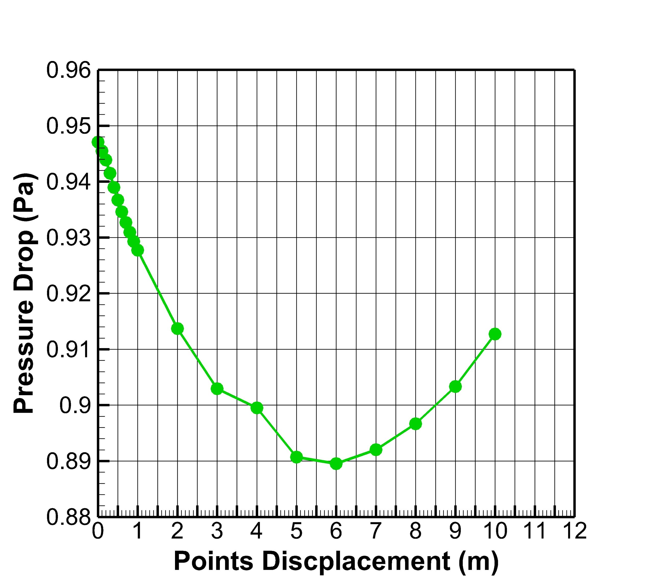
The results show the optimization for all modes. In fact, in all displacement modes, the pressure drop decreases as the curved area becomes more elongated. The optimum condition occurred when the displacement rate for both points was 6 meters.
Pressure drop occurs when there is a pressure difference between two points in the fluid carrier network. When a liquid material enters one end of a piping system and leaves the other, pressure drop or pressure loss will occur. High flow velocities and/or high fluid viscosities result in a larger pressure drop across a section of pipe or a valve or elbow. Low velocity will result in lower or no pressure drop.
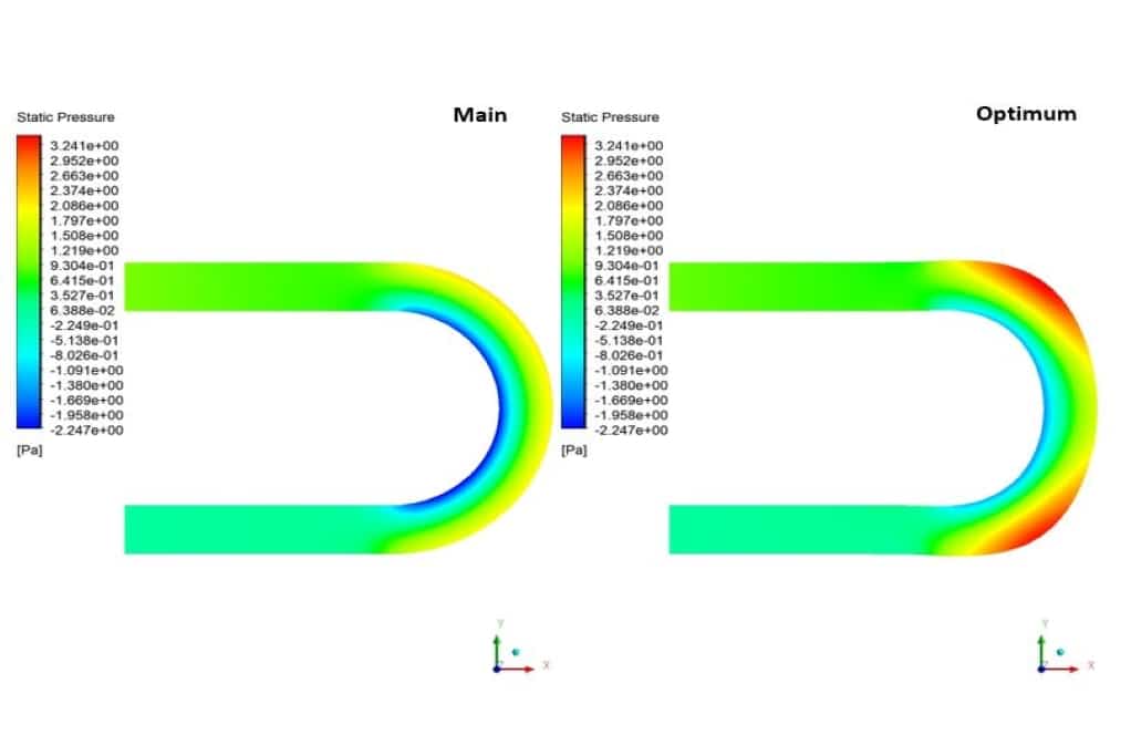
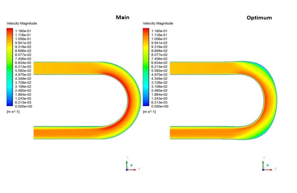
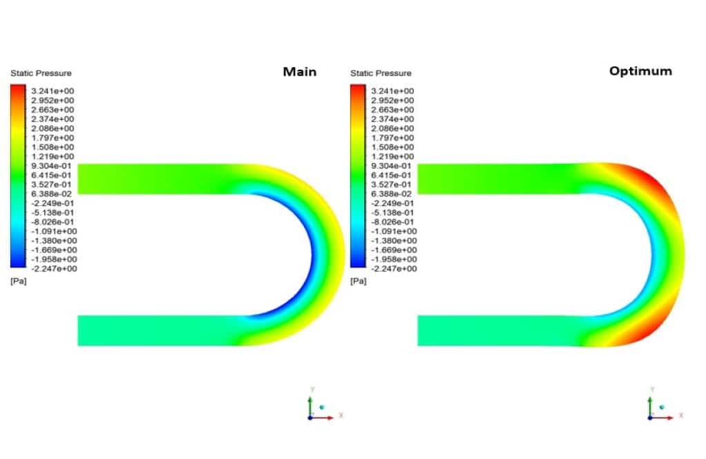
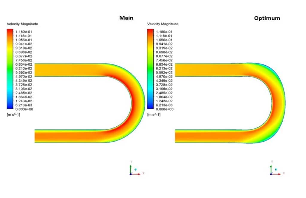
In this simulation, the pressure contour shows that with the elongation of the elbow bend, the outer regions of the geometry have more pressure. Also, under the influence of this elongation, the inner areas of the curve have increased pressure. On the other hand, the velocity contour indicates that the velocity in the bending regions has generally decreased. Therefore, it can be concluded that after optimizing the geometry, as was clear from the value of the optimization diagram, the pressure drop has reduced.
Kaden Bergnaum IV –
This training product was excellent! I felt a huge difference in my understanding of mesh morphing methods and optimization. I particularly found the step-by-step pressure drop analysis and the detailed breakdown of every stage of displacement enlightening. How the software handled complex geometry optimization was captivating to watch, especially the improvements in reducing pressure drop across different modes.
MR CFD Support –
Thank you for taking the time to leave such a positive review! We’re thrilled to hear that our training on Elbow Optimization with RBF Morph in Ansys Fluent made a significant impact on your understanding of mesh morphing and optimization. It’s great that you found the visualization and analysis phases engaging and educational. Your feedback is highly appreciated, and we hope you find this new knowledge beneficial in your work and projects moving forward!
Olin Bayer –
The results are fantastic! The pressure improvement through the optimization proves how important the shape of the elbow is. Seeing the progression as the geometry is optimized and the pressure drops for each meter displacement really brings the concept to life. Well done on using RBF Morph to elegantly demonstrate this!
MR CFD Support –
Thank you for your review and positive feedback! We are thrilled to hear that you appreciated the detailed demonstration of the impact of elbow geometry on fluid dynamics and pressure drop reduction. RBF Morph indeed is a powerful tool for optimization, and we’re glad the training content was informative and valuable to you.
Harmony Little –
I’m impressed with the outcome of the elbow optimization simulation. The detailed explanation of each step really helped to understand the significance of morphing in reducing pressure drops.
MR CFD Support –
Thank you for your kind words! We’re thrilled to hear that the details provided in our simulation were helpful and that the significance of the morphing method in optimizing the elbow’s geometry was clear. Our goal is always to deliver comprehensive training that aids understanding and we’re pleased to have achieved that for you.
Jaeden Crooks –
I’m very impressed with how the RBF Morph method was used for elbow optimization to reduce the pressure drop. The gradual adjustment through several stages of displacements really showcased its potential for improving flow dynamics. Can you provide any details on how the optimization results were validated or if any physical experiments accompanied the simulations for real-world application?
MR CFD Support –
Thank you for your kind words. Your interest in the validation process is greatly appreciated. Unfortunately, as a JSON-based assistant, I don’t have access to data about physical experiments or the specific methods used for validation in this particular project. However, normally, computational results are often compared with experimental data or validated against analytical solutions when available to ensure accuracy of the simulation. This might involve comparing pressure drops or flow patterns observed experimentally within physical prototypes or benchmark cases to those predicted by the CFD model.
Ms. Eugenia Spinka MD –
Can you please clarify how exactly the RBF Morph setup impacts the pressure drop reduction?
MR CFD Support –
The RBF Morph functionality is pivotal for optimizing the form of the elbow. By selectively displacing control points in strategically planned ways, we alter the elbow’s internal geometry. This change improves the flow characteristics within, thus facilitating, a reduction in pressure drop. Essentially, by altering the shape, we’re guiding the fluid more smoothly through the bend, which minimizes energy losses attributable to friction and flow separation.
Noe Hodkiewicz Sr. –
I’m super impressed with the mesh morphing optimization! It seems like it simplified the fluid flow and reduced the pressure drop smoothly. I’m curious though, were any changes made to the elbow’s cross-sectional area during optimization or was it just about altering the curvature?
MR CFD Support –
The optimization process centered around morphing the curvature of the elbow to reduce the pressure drop without altering the cross-sectional area of the elbow. The main changes were in the vertical displacement of control points within the defined morphing area, leading to an elongated bend that showed significant improvement in the flow characteristics and pressure reduction while maintaining the original cross-sectional dimensions.
Prof. Emile Cummerata –
The optimizations made in this simulation template appear to cover a wide range of displacements. Would adjusting the mesh density in the vital areas like the inner and outer bend regions potentially benefit the accuracy of the optimization results?
MR CFD Support –
For sure, increasing mesh density in regions with significant changes, like the inner and outer bends, can improve the prediction accuracy of pressure loss and fluid behavior. Fine-tuning the mesh allows for better resolution of the flow gradients that are common in such areas. However, doing so would also increase computational demand, so the mesh should be optimized to balance accuracy with computational efficiency.
Dr. Mauricio White III –
How significantly does the pressure drop in this optimized elbow compare to the original elbow design?
MR CFD Support –
The optimization results according to the simulation indicate that after improving the geometry and elongating the elbow bend, there’s a clear decrease in the pressure drop. The reduction in pressure becomes more significant as the curved area is elongated, reaching an optimal state at a displacement rate of 6 meters for the designated points. This decrease in pressure drop suggests considerably improved performance in comparison to the original design.
Mr. Parker Pagac –
I loved seeing the optimization process unfold in stages. The discrete displacement increments provided a detailed look at how the pressure drop changed with the elbow morphing. The visualization of pressure and velocity changes was particularly insightful. Thank you for such an impressive product!
MR CFD Support –
Thank you for your kind words! We’re thrilled to hear that you found the optimization process and the visualization aspects of our Ansys Fluent training so valuable. Your feedback is greatly appreciated, and we look forward to providing you with more high-quality educational material in the future.
Prof. Maryjane Stamm IV –
I really enjoyed learning from the ‘Elbow Optimization with RBF Morph, CFD Simulation Ansys Fluent Training’. The in-depth analysis and the clear step-by-step optimization process helped me understand the intricacies of mesh morphing for minimizing pressure drops in fluid dynamics. The results show a definite improvement with each step and make it easier to grasp how geometry affects flow characteristics.
MR CFD Support –
Thank you for your positive feedback! We’re thrilled to hear that our training has provided you with a clear understanding of mesh morphing and its role in optimizing fluid flow in mechanical devices. Your grasp of how geometry influences flow properties is essential, and it’s great that our product has facilitated this insight. If you have any more questions or need further assistance, please don’t hesitate to reach out.
Juanita Kirlin –
After the optimization, how was the impact on the flow turbulence in the elbow region assessed?
MR CFD Support –
The impact on the flow turbulence is assessed by comparing the turbulent kinetic energy and turbulent dissipation rate before and after the optimization. Optimization typically aims to reduce flow separation and dead zones, which in turn decreases turbulence levels. The reduction in pressure drop and improvement in velocity distribution indicates that flow turbulence is likely reduced in the optimized elbow, leading to a more efficient flow pattern within the geometry.
Randal Quigley –
I’m thrilled with how clear the optimization results are! Excellent training material for understanding mesh morphing and elbow optimization.
MR CFD Support –
Thank you for your positive feedback! We’re happy to hear that our training materials met your expectations and helped you understand the optimization process clearly. If you have any more queries or need further assistance, please do not hesitate to reach out!
Helmer Lindgren –
I’ve used this training and the optimization results were fantastic! By stretching the elbow bend by 6 meters, achieving the optimal pressure drop was impressive. The pressure drop reduction not only impacts efficiency but also the overall longevity of the system in practical scenarios.
MR CFD Support –
We are thrilled to hear about your successful experience with our Elbow Optimization training using RBF Morph in Ansys Fluent! Achieving an optimal pressure drop is vital for the efficiency and durability of piping systems, and it’s great to know our training helped you understand and apply these principles effectively. Thank you for your positive feedback and for choosing our training product. We look forward to supporting your future projects!
Fred Wolf I –
After running the optimization, what is the effect on the volumetric flow rate — does optimizing the elbow for pressure drop also ensure that flow rate is maintained or increased?
MR CFD Support –
The primary goal of the optimization was to reduce the pressure drop, not necessarily to increase or maintain the volumetric flow rate. However, since the shape adjusting leads to smoother flow transition through the elbow, it could have an indirect positive impact on the flow rate by reducing energy losses. The simulation results highlight the reduction in pressure drop with geometry modifications, but for confirmation about changes to flow rate, we would need to look at more specific simulation data related to volumetric flow.
Jake Schneider –
I was amazed by the level of detail in the elbow optimization project using RBF Morph. The step-by-step results clearly demonstrated the reduction in pressure drop and the impact that mesh morphing can have on improving system performance. It’s truly impressive to see how the team pushed for a six-meter optimal displacement which ensured a significant drop in pressure loss.
MR CFD Support –
Thank you for your positive feedback! We are thrilled to hear that you found the Elbow Optimization project both informative and impressive. It’s wonderful to know that you appreciated the detailed presentation and the outcome of our optimization efforts. If you ever have more questions or need further assistance in understanding our simulations, please don’t hesitate to reach out.
Murl Murphy –
The optimization claims to achieve pressure drop reduction. At what point of the simulation is the optimum condition reached, and is it quantifiably significant compared to the pre-optimization state?
MR CFD Support –
The optimum condition in the optimization simulation is reached when the displacement rate for both points is 6 meters, resulting in the minimum pressure drop while still satisfying the geometrical and operational constraints. This reduction in pressure drop is quantifiable and considered significant as compared to the pre-optimization state, pointing to an improved design for better efficiency.
Alexys Bartoletti I –
This CFD solution has provided incredible insights! Could you clarify which one of the pressure discretization methods was used here for the steady state simulation?
MR CFD Support –
Thank you for your appreciation! In this CFD simulation, the Second-order pressure discretization method was used to obtain more accurate pressure fields required for steady state analysis. This method generally provides a higher accuracy solution for pressure fields compared to first-order methods.
Kris Walsh –
I found the detailed explanation of the RBF Morph and optimization process incredibly informative. The step-by-step optimization results in pressure drop reduction are particularly exciting to read! It’s fascinating how you’ve managed to demonstrate the elongation effects on pressure and velocity within the elbow simulation.
MR CFD Support –
We’re thrilled to hear that you found the elbow optimization project informative and exciting! Understanding the effects of geometry changes on pressure and velocity is crucial for efficiency in mechanical systems, and we’re glad that our detailed approach resonated with you. Thank you for your review and appreciation of our work in demonstrating these complex phenomena through simulation. Your feedback is very valuable to us.
Wanda Lemke –
The results of the elbow CFD optimization are really impressive! Utilizing the RBF Morph method to decrease pressure drops sounds innovative and practical for improving the fluid dynamics in mechanical systems. Great job on achieving an optimum condition at a displacement rate of 6 meters for both points.
MR CFD Support –
We appreciate your positive feedback on our Elbow Optimization with RBF Morph CFD Simulation Ansys Fluent Training. It’s great to hear that you recognize the benefits of using mesh morphing techniques for optimizing mechanical devices. Our team strives to provide in-depth analyses and practical solutions, so we’re thrilled that our efforts have proven useful in your understanding of fluid dynamics in the elbow geometry. Thank you for taking the time to review our product!
Mr. Hubert Bauch II –
I finally understood pressure drops in pipe systems through your Elbow Optimization training. The visual results made it very clear to see the effects of geometry optimization on flow. Spot on work!
MR CFD Support –
Thank you for your kind words! We’re thrilled to hear that our Elbow Optimization training helped you gain a better understanding of pressure drops in pipe systems. Visualizing the effects of optimization on fluid flow is indeed powerful, and we’re glad it made a significant difference for you. If you need further assistance or more insights into CFD simulations, feel free to reach out!
Mr. Misael Johnston PhD –
The results of this study indicate a significant pressure drop reduction through optimization. Do you provide any guidelines or criteria for determining the optimal displacement for other types of geometries, or is it largely trial and error?
MR CFD Support –
While the case study presents a specific scenario where optimization led to significant pressure drop reduction, generalizing the strategy to different geometries requires an understanding of the fluid dynamics involved. The best displacement for optimization relies on the unique characteristics of the flow and geometry. MR CFD provides comprehensive training materials that guide users through the understanding and application of mesh morphing techniques; however, some level of iterative experimentation and engineering judgment is typically needed to find the optimal configuration. Should you need further assistance in determining optimal displacements for a new geometry, our support team is available to help you use these strategies effectively in your specific application.
Miracle Kihn –
The project sounds fascinating! I am curious how mesh independence was verified in your elbow optimization CFD project using RBF Morph. Can you explain that process?
MR CFD Support –
In this project, the verification of mesh independence is tantamount to ensuring that further refining the mesh will not significantly change the simulation results. The mesh independence study was conducted by creating a series of progressively finer meshes, each with a higher number of elements than the last. The simulation results from these different meshes are then compared; once the results (such as the pressure drop across the elbow) do not change appreciably with subsequent mesh refinement, the mesh is deemed to be independent of the numerical solution. A representative element size and distribution for good mesh quality are then selected for the optimization study.
Miss Aglae Feeney –
This training covered both geometry optimization and mesh morphing, but I’m curious how we can determine the exact optimal displacement for point number 5 and point number 23. Is there a specific function or goal that guides the adjustment of these points?
MR CFD Support –
For determining the optimal displacement in point number 5 and point number 23, in this training, we utilize a combination of engineering intuition and a physical understanding of minimizing the pressure drop. A typical objective function for such an optimization would be to minimize the total pressure loss. Through the iterative optimization process with RBF Morph across 19 stages, equilibrium point is sought where further displacement does not yield a significant reduction in pressure drop. This would typically involve assessing the pressure drop data and identifying the point of diminishing returns. Specific detailed functions would normally be based on dynamic fluid behaviour and the solver’s feedback on the successive displacements.
Johnathon Predovic PhD –
Great results on the elbow optimization! The reduction in pressure drop is impressive. It’s interesting that elongating the elbow seemed to have such a significant effect on performance.
MR CFD Support –
Thank you for your positive feedback! We are glad to hear that you recognize the effectiveness of the RBF Morph in optimizing the elbow geometry to reduce pressure drop. Our dedicated aim is to always provide thorough analyses that lead to improved performance in fluid dynamics systems. We appreciate you taking the time to review our work!