Boat Propeller Transient Solution, ANSYS CFX Training
$120.00 Student Discount
- The problem numerically simulates the rotation of Boat Propeller using ANSYS CFX software.
- The geometry is designed in a 3D model with the SpaceClaim software.
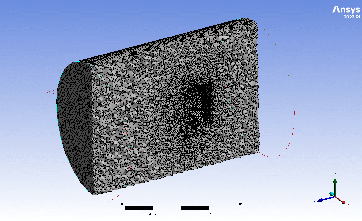
- We performed the mesh of the model with ANSYS Meshing software, and the element number equals 4,037,941.
- The solution is carried out in transient form.
- Transient Rotor Stator is set for frame change model of the interfaces.
To Order Your Project or benefit from a CFD consultation, contact our experts via email ([email protected]), online support tab, or WhatsApp at +44 7443 197273.
There are some Free Products to check our service quality.
If you want the training video in another language instead of English, ask it via [email protected] after you buy the product.
Description
Description
This project uses the ANSYS CFX modeling application to simulate the rotational movement of a boat propeller in Transient form.
A propeller converts torque, or the force that causes anything to revolve, into thrust. Water moves behind and downhill behind the blades of a rotating propeller, creating a thrust of water from the blades.
Each blade has a specific curved shape that, when it turns, helps to move the water below it and away from it, acting as a foil to do so before pushing the water out from behind.
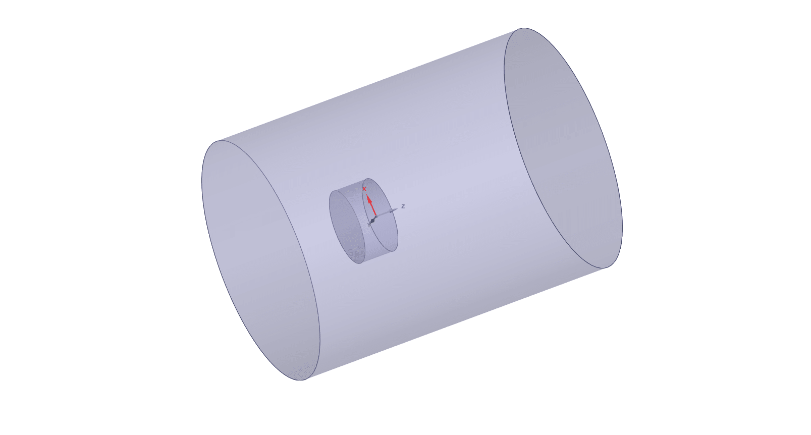
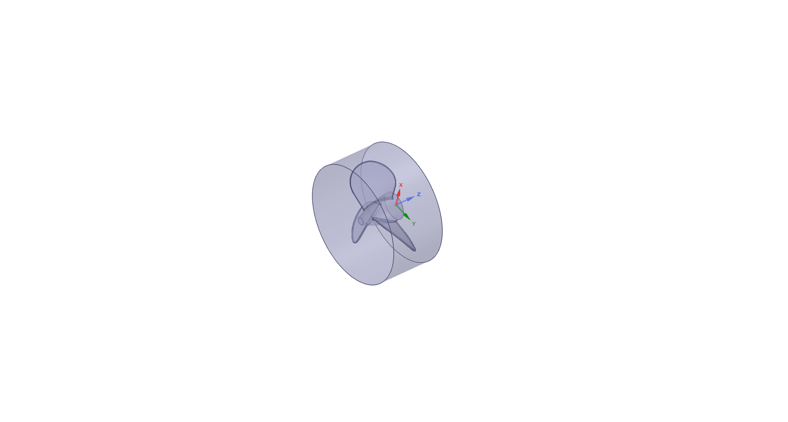
The 3D geometry of the solution is designed in SpaceClaim software. The propeller is placed at middle of the domain and closer to the inlet. The waterflow enters the domain with the velocity of 20m/s while the propeller rotates with the rotational velocity of 1500 rad/sec.
The simulation is carried out for 0.08sec.
Then the geometry is connected to the ANSYS Meshing software. The elements with a high quality are produced in tetrahedral type.
Furthermore, 5 layers of inflation is set around the circle which results in elements equal to 1,746,106 and 2,291,835 for stationary and rotating zones, respectively.
Methodology: Boat Propeller Transient Solution
The simulation runs considering time (Transient state). Gravitational impacts are also disregarded.
The turbulence model is Shear Stress Transport (k-ԑ SST).
The domain motion of the propeller zone is set to rotating. Also, the Frame Change/Mixing Model of the interfaces of rotationary and stationary zones are set to Transient Rotor Stator.
The Advection Scheme, Transient Scheme and Turbulence Numeric are set to upwind, second order backward order and First order, respectively.
Results
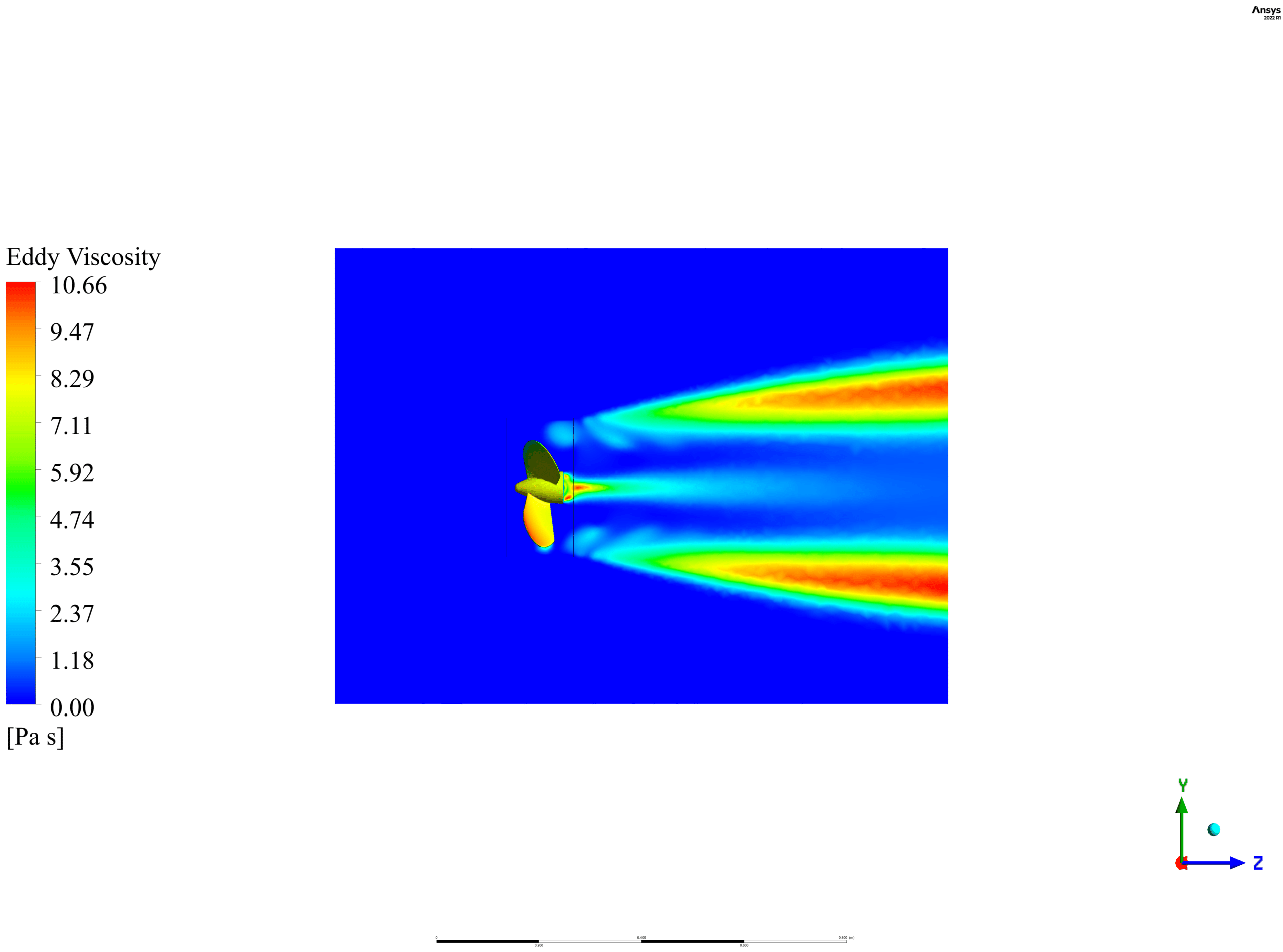
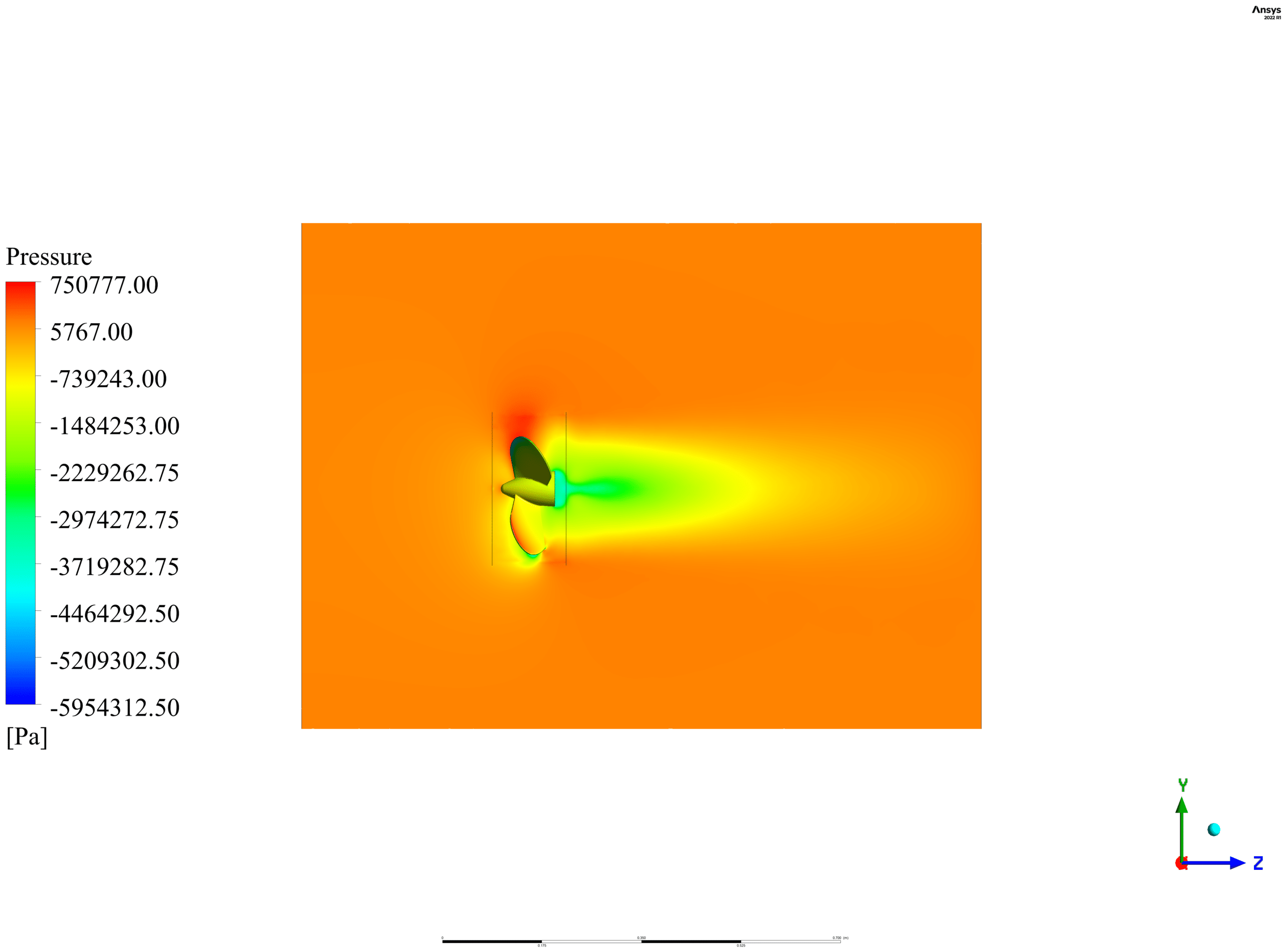
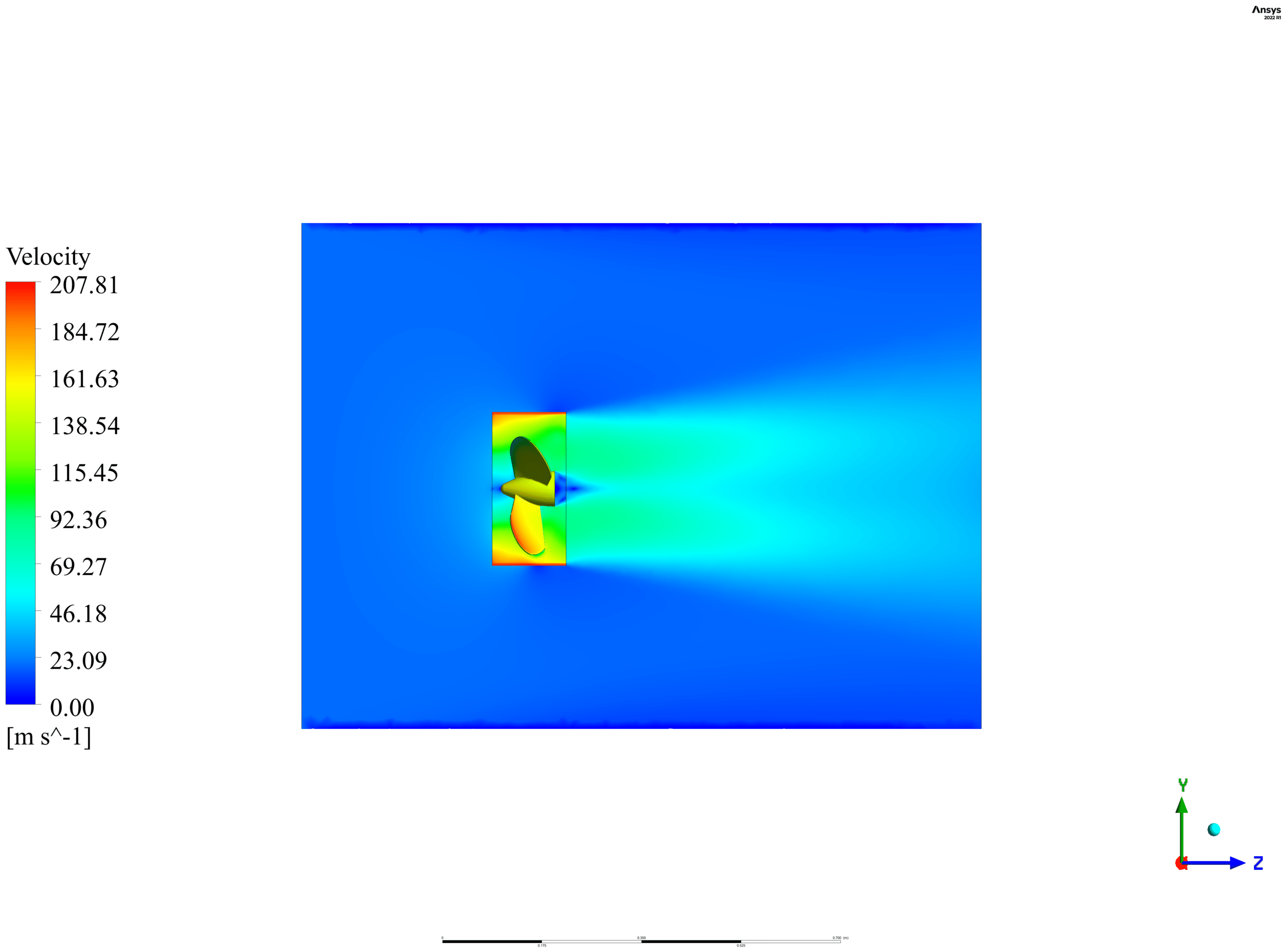
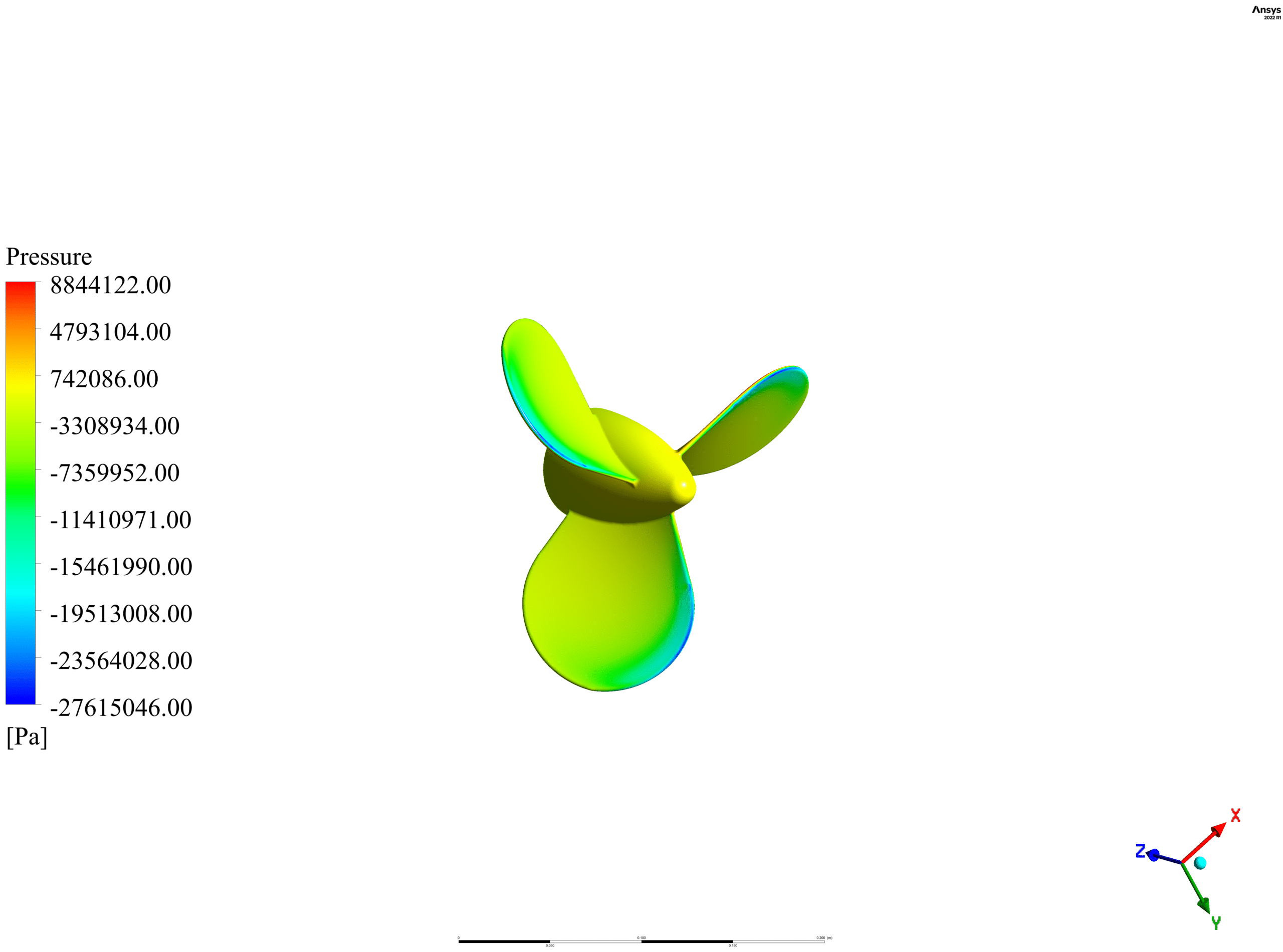
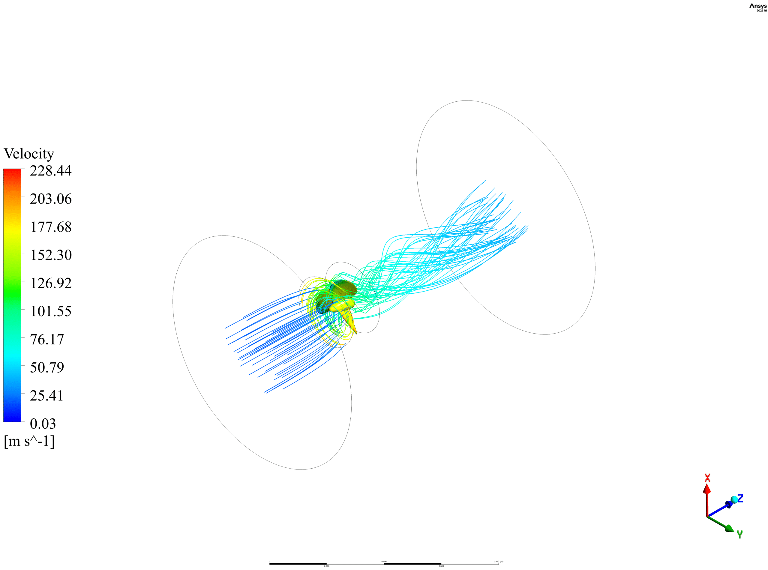
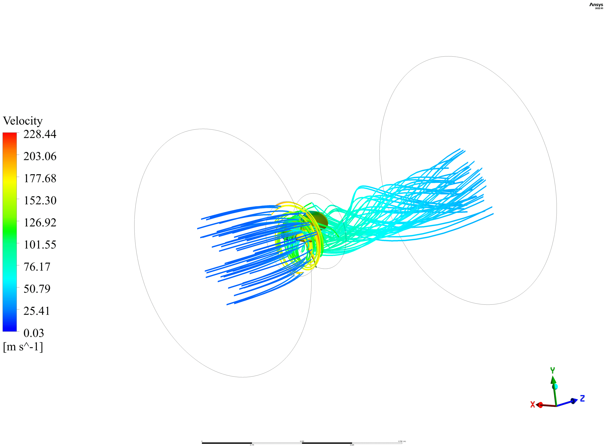
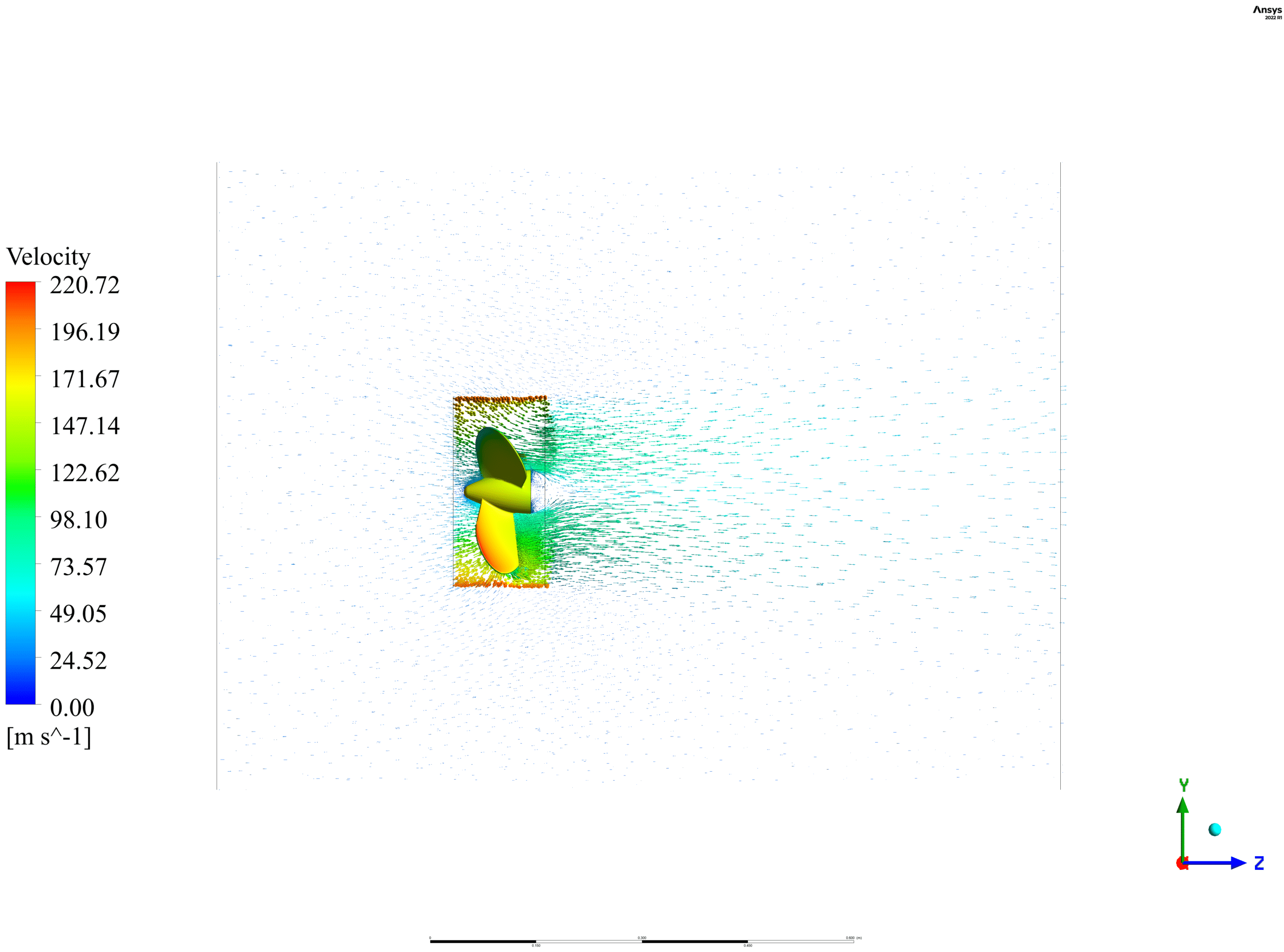
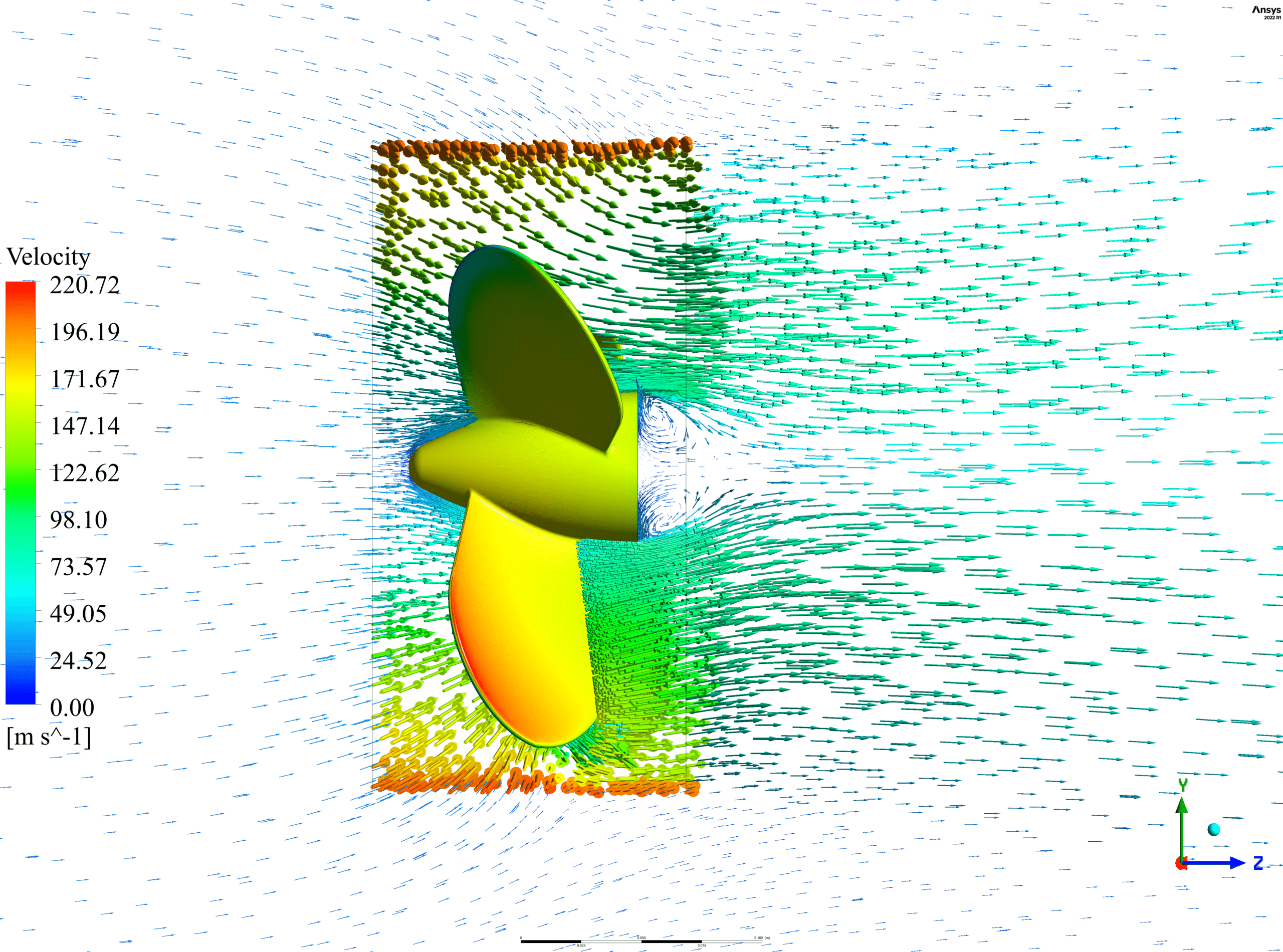
At the end of the solution process, two-dimensional contours, vectors and streamlines related to velocity, pressure, Eddy viscosity and the Turbulence Kinetic Energy are obtained.
As shown in the figures, the pressure amount on the propeller is visible.
The periodic behavior of waterflow over time is displayed in animations exported from CFD-Post software.
Additionally, if you give closer attention, you can see the vortexes behind the propeller via the vectors and streamlines.

Eldon Gibson –
I recently finished the Boat Propeller Transient Solution ANSYS CFX training and found the balance between theory and practical application to be excellent. The inclusion of high-quality meshing details and animations of the waterflow proved incredibly helpful for my understanding of how a propeller influences water movement.
MR CFD Support –
Thank you for your kind words! We’re thrilled to hear that our training materials met your expectations and provided clarity on the complexities of boat propeller simulations. We aim to offer a blend of theoretical knowledge and practical application to ensure a comprehensive learning experience. Keep an eye out for more engaging content in the future!
Friedrich Kovacek –
The project details are fascinating! The visualizations must have been very helpful in understanding the flow patterns. Great project execution!
MR CFD Support –
Thank you for your kind words! We’re thrilled that you found the project and its visualizations insightful. It’s always our goal to ensure users can clearly understand the simulations and outcomes. If you have any more feedback or need further assistance in future projects, please don’t hesitate to ask.
Stephon Swaniawski –
I’m truly impressed by the Boat Propeller Transient Solution training. The detail provided in the methodology and analysis speaks to the thoroughness with which the training was conducted. Using a second-order backward Transient Scheme and first-order Turbulence Numeric to generate insights on the propeller’s performance under transient conditions is top-notch. Seeing the periodic behavior of water flow and propeller-linked vortexes helps to grasp the complexities of marine propulsion. Great use of CFX!
MR CFD Support –
Thank you for your kind review! We are delighted to hear that our Boat Propeller Transient Solution training was impressive and informative for you, especially with the insights into the sophistication of the transient analysis and the visualization of the fluid dynamics. We always strive to provide high-quality learning products that enable a deep understanding of complex simulations. If you have further inquiries, never hesitate to reach out!
Mrs. Jammie Lubowitz MD –
Really cool results! The animations must give a clear view of the flow behavior, and having those pressure contours must provide great insights for propeller design optimizations.
MR CFD Support –
Thank you for your positive feedback! We are delighted to hear that the results and the animations have provided you with useful insights. Seeing the physical phenomena such as the vortexes and the flow behavior come to life through these simulations is indeed fascinating. If you need further information or assistance, feel free to reach out to us. We appreciate your support and look forward to serving you again in the future!
Winifred Donnelly V –
I just wanted to say that the detailed results and the discussion on the vortexes forming behind the propeller were really insightful. The data on Eddy viscosity and Turbulence Kinetic Energy was particularly fascinating.
MR CFD Support –
Thank you so much for your positive feedback! We’re thrilled to hear that you found the simulation results and the analysis on the propeller’s vortexes informative. It’s our goal to provide detailed and valuable insights into fluid dynamics with our CFD products. If you have any more questions or need further assistance, feel free to reach out.
Prof. Mohamed Senger –
I was thoroughly impressed with how the Boat Propeller Transient Solution training made complex concepts approachable. Seeing the animations and understanding the fluid dynamics per the propeller’s movement was enlightening. I especially appreciated the clear illustrations of pressure distribution and vortex formation.
MR CFD Support –
Thank you for your positive feedback! We’re thrilled to hear that our training material could clearly convey complex simulation insights in an understandable way. It’s fantastic to know that the animations and visual representations of pressure and vortex dynamics enhanced your understanding. We strive for such clarity in our materials, and your appreciation keeps us motivated.
Ms. Dariana Stokes Jr. –
I’ve learned an incredible amount from the Boat Propeller Transient Solution, ANSYS CFX training. The methodology used was thoroughly comprehensive, the instructions clear, and it deepened my understanding of how propellers generate thrust. The attention to details, like using a high-quality tetrahedral mesh and accounting for rotational zones, really showcases the caliber of truth behind modeling with ANSYS products. It’s evident that every aspect, from geometry preparation in SpaceClaim to setting up the transient solver conditions, was geared towards capturing nuanced flows created by the propeller. Very well-done MR CFD Company on creating an engaging and educational experience!
MR CFD Support –
Thank you so much for your kind words! We at MR CFD Company are thrilled to hear that you found the Boat Propeller Transient Solution, ANSYS CFX training to be informative and comprehensively detailed. It’s great to know our dedication to providing an accurate and nuanced understanding of CFD is valuable to our customers. Your feedback provides us with encouragement to continue producing high-quality learning products. If there’s anything else we can help you with, feel free to reach out.
Kaya Rodriguez –
I’m really impressed with the detail covered in this boat propeller transient simulation, especially the animations that show the periodic behavior of waterflow and vortexes behind the propeller. It’s wonderful to see how effective the model was in illustrating the rotational forces and their effects on fluid dynamics.
MR CFD Support –
Thank you for your kind words! We’re thrilled to hear that the level of detail and the animations provided a clear understanding of the boat propeller’s dynamics. Your appreciation means a lot to us, and it encourages our team to keep offering high-quality and informative simulations. If you have any more questions or require further assistance, please don’t hesitate to reach out.
Noel Shields I –
I found the animations extremely helpful for visualizing the flow patterns. The water movement and the vortexes created were quite easy to distinguish.
MR CFD Support –
Thank you for your kind feedback! We’re glad to hear that the animations proved to be a useful tool for visualizing the simulation results.
Esmeralda Koepp –
The project results mention a ‘periodic behavior of waterflow over time.’ Can you elaborate on what kind of periodic behavior was observed and what may have caused this pattern?
MR CFD Support –
The periodic behavior observed in the boat propeller simulation refers to a recurring pattern in the water flow caused by the rotating propeller blades. Each blade’s passage through the water generates vortices and pressure variations, which repeat with every revolution of the propeller, thus making the pattern periodic. This periodic behavior is captured in the Transient simulation and is largely due to the propeller’s rotational motion and the interactions between the moving blades and the water.
Kiera Bartell –
The simulation appears fascinating. How do the second-order backward and first-order schemes complement each other here for accuracy and stability?
MR CFD Support –
In this simulation, the second-order backward transient scheme is used to enhance temporal accuracy by considering information from the past two time levels, which provides a more accurate representation of temporal changes. The first-order spatial scheme offers good stability, especially necessary in highly non-linear and transient flow scenarios like the one with the boat propeller. This approach aims to deliver a balanced simulation where time accuracy and spatial stability are optimized.
Miss Stephanie Schinner II –
I’ve followed the Boat Propeller Transient Solution tutorial and the results are fantastic. The animations really helped me understand the fluid dynamics around the rotating propeller. Great job on the clarity of the content!
MR CFD Support –
Thank you for your kind words! We are delighted to hear that our Boat Propeller Transient Solution tutorial has assisted you in understanding fluid dynamics and that our animations have been particularly helpful. We strive for such clarity in our educational content, and it’s great to know it’s appreciated!
Macy Gutkowski –
Absolutely phenomenal learning material! The step-by-step elucidation of the transient solution for a boat propeller using ANSYS CFX is exceptional. The explanation of the curvature and movement of the propeller blades was detailed, and the integration between the geometry in SpaceClaim and mesh generation in ANSYS Meshing software demonstrated a seamless workflow. The breakdown of setting up the simulation, including the intricacies of boundary conditions such as the rotatory zone and the interface settings like the Transient Rotor-Stator model, is truly instructive for interpreting the dynamic behavior of propellers. It’s impressive to see the presentation of results in various forms, including contours and streamlines, to understand the resultant pressure and water flow. The tutorial certainly provided an in-depth understanding of rotational fluid dynamics and would be an invaluable resource for anyone looking to execute similar CFD tasks.
MR CFD Support –
Thank you for your generous feedback! We’re grateful to hear that you found the tutorial informative and helpful for your understanding of complex CFD phenomena. At MR CFD, it’s our goal to provide clear and comprehensive learning materials, and it’s rewarding to know we are meeting that expectation. We’re looking forward to bringing you more valuable applications and solutions. If you ever have any questions or feedback, please don’t hesitate to reach out.
Aurore Sawayn –
I am thrilled with the Boat Propeller Transient Solution training from MR CFD! The step-by-step guide through the rotation of the blades and the visualization of the water movement was outstanding. Learning how the propeller’s thrust is generated and observing the pressure changes and the periodic behavioral patterns of water flow were incredibly insightful.
MR CFD Support –
Thank you for the positive feedback! We’re glad to know our Boat Propeller Transient Solution training provided you with clear insights and visual understanding of the complex dynamics involved. Your experience reaffirms our commitment to offering high-quality learning materials. If you have any more questions or need further assistance, don’t hesitate to get in touch!
Nya Reinger –
The graphics and animations provided in the results are impressive! They allow me to grasp the dynamic behavior of the boat propeller in water. I’m particularly fascinated by the visualization of the pressure distribution and the vortices formed. Great job on capturing the transient nature of the flow!
MR CFD Support –
Thank you so much for your positive feedback! We are delighted to hear that our graphics and animations helped you understand the complexities of boat propeller dynamics. Our goal is to provide clear and informative visualizations that aid in interpreting CFD results. If you have any further questions or need more information, feel free to reach out!
Randy Koelpin –
Wow! This ANSYS CFX propeller simulation project seems very comprehensive. Great job on setting up such an intricate model and capturing the turbulent water flow and resultant forces on the propeller.
MR CFD Support –
Thank you for your review! We’re thrilled to hear that you appreciate the complexity and detail involved in the Boat Propeller Transient Solution project. It was our goal to provide a highly realistic and informative simulation, and we’re glad you recognized our efforts. If you have further questions or need assistance with similar projects, feel free to ask!
Mrs. Chelsea Yundt Jr. –
The Boat Propeller Transient Solution project sounds fascinating! I’m curious about the animation—it seems like it would provide excellent visual insight into the flow behavior. Can you tell me more about how the animation is created and what it helps to visualize?
MR CFD Support –
The animation mentioned in the Boat Propeller Transient Solution project is created using results from the final simulation data. It’s produced in the CFD-Post software, a post-processing tool that accompanies ANSYS software suite. The animation illustrates the periodic behavior of water flow and propeller interaction over time by showing movement such as velocity fields, pressure variations, and vortex formation. This dynamic visualization helps in understanding the performance and efficiency of the propeller as well as the flow characteristics like vortices, which are critical to the propulsion of a boat.