Check Valve CFD Simulation, Dynamic Mesh
$140.00 Student Discount
- The problem numerically simulates the Check Valve using ANSYS Fluent software.
- We design the 2-D model with the Design Modeler software.
- We mesh the model with ANSYS Meshing software, and the element number equals 14,586.
- We perform this simulation as unsteady (Transient).
- We use the Dynamic Mesh Model to define deforming and moving zones.
- We use the 6-DOF solver to define the rotational motion of the valve.
- We use the VOF Multiphase Model to define the air and water.
- We use the Execute Command to define the interruption of the input flow.
To Order Your Project or benefit from a CFD consultation, contact our experts via email ([email protected]), online support tab, or WhatsApp at +44 7443 197273.
There are some Free Products to check our service quality.
If you want the training video in another language instead of English, ask it via [email protected] after you buy the product.
Description
Description
This project is related to the numerical flow simulation through the Check Valve using ANSYS Fluent software. A check valve is a unidirectional valve that passes fluid in one direction but prevents no flow in the opposite direction.
This product is the third chapter of the Dynamic Mesh Training Course.
In this project, we considered a pipe in which water flows. We put a check valve in the water flow path in the pipe. We also put a seat valve behind this valve. This causes the valve to operate in one direction.
First, on the way, the fluid hits the valve and opens it. Then, when the inflow is interrupted, the fluid on the return path hits the valve again and closes it.
This project aims to model the check valve motion inside the pipe. As the valve inside the tube opens and closes, the mesh of the computational zone undergoes deformation over time.
We modeled the geometry of the project using Design Modeler software. The geometry corresponds to a horizontal pipe with a check valve. In the middle of this pipe, a simple valve with a seat valve is designed. Then we meshed the model with ANSYS Meshing software. The model mesh is unstructured, and the number of cells equals 14,586.
Check Valve Methodology
The Dynamic Mesh Model is used in this simulation. We generally use a dynamic mesh whenever we have a moving boundary or a deforming zone.
Here, a valve has a rotational motion inside a pipe. So this causes the mesh to deform over time.
The fluid flow inside the pipe causes the valve to move by hitting the valve. By applying the force of fluid flow, the valve starts to rotate around its central axis.
So we use six degrees of freedom (6 DOF) solver. The 6-DOF solver allows the object to move in six degrees (three degrees of freedom in translational motion and three degrees of freedom in rotational motion). This means that by defining data such as mass and inertia tensor, etc., we allow the solver to move the object.
In this simulation, the valve only rotates on its axis. So we have to limit the movement of the valve to one degree of freedom rotational motion.
Now, we must define the rotational motion of the valve. We have to define the boundary related to the valve walls as a Rigid Body; so that we define motion for these rigid bodies.
To define the movement of the valve, we use the motion defined by the 6-DOF solver.
According to the rotational motion of the valve as a rigid body, the mesh zone inside the tube is deformed. So, for this zone, we use the Deforming option.
Due to the nature of this modeling, flow behavior is time-dependent. Hence, we use the unsteady (Transient) solver.
We want the pipe to be empty of water flow at first. That is, there is only air in the inner space of the tube. Then the water flow enters the pipe. So in this simulation, we need two fluids.
Therefore, we use the Multiphase Model. Since the flow of water and air are separate and have a distinct separation boundary, we use the volume of fluid (VOF) multiphase model.
We aim to cut off the incoming water flow after a specific time to see the return of the flow and, consequently, the closing of the valve. We used an Execute Command to define the interruption of the input flow.
Check Valve Conclusion
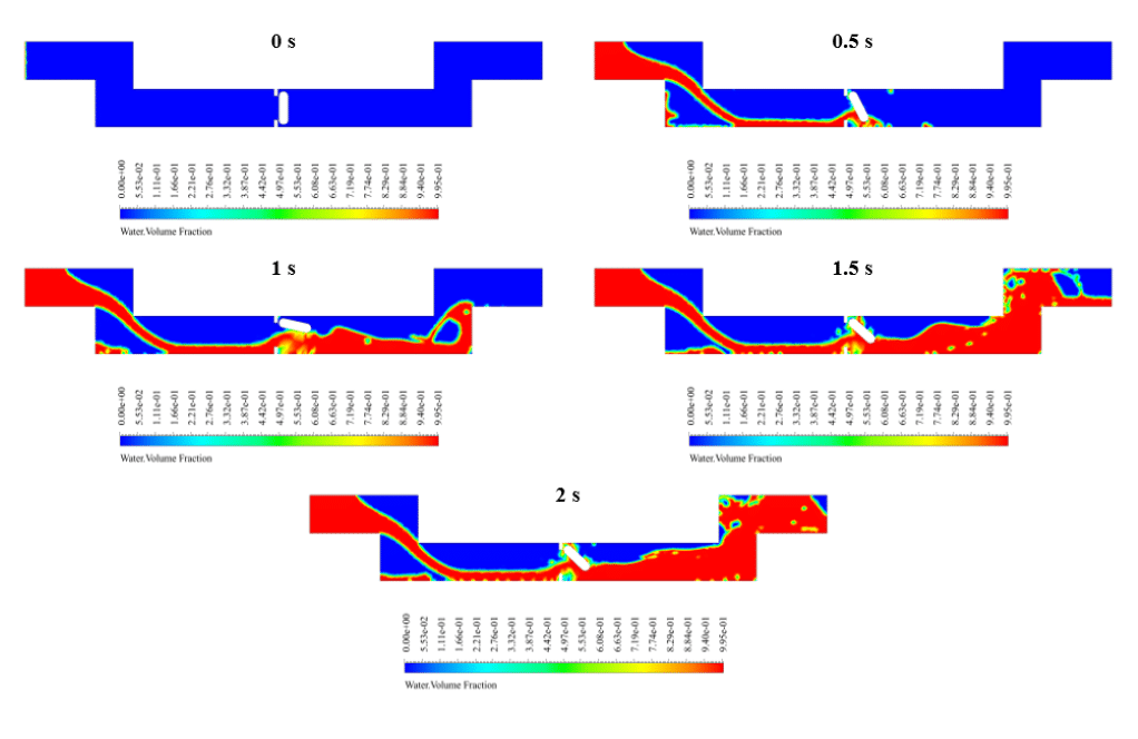
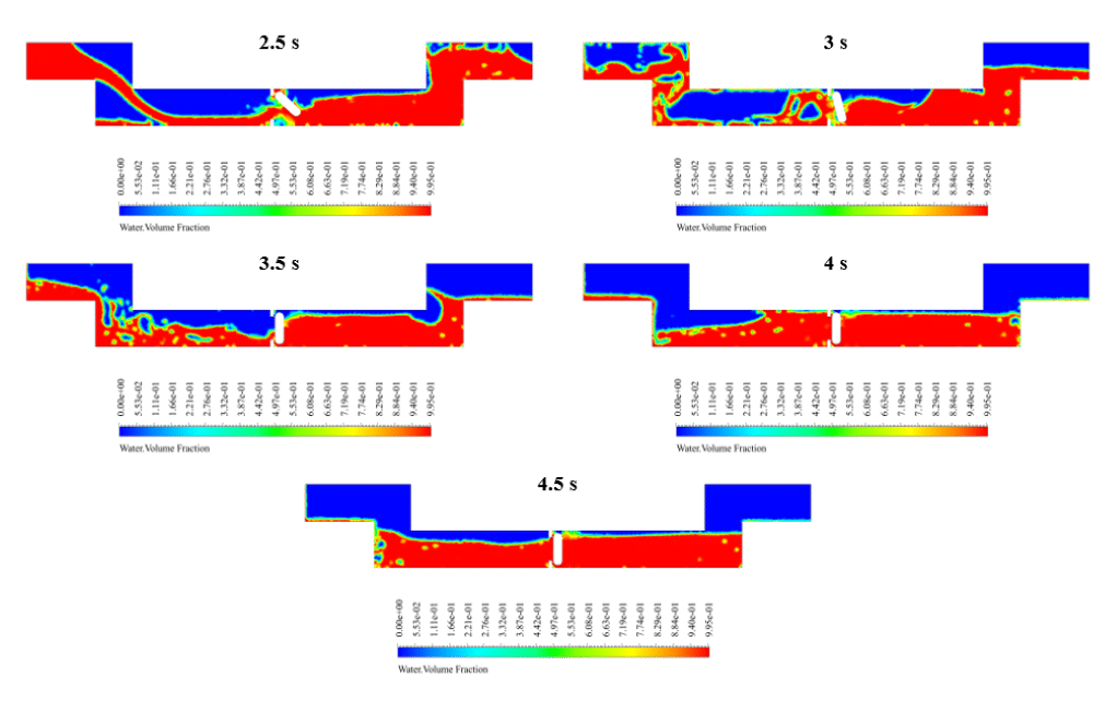
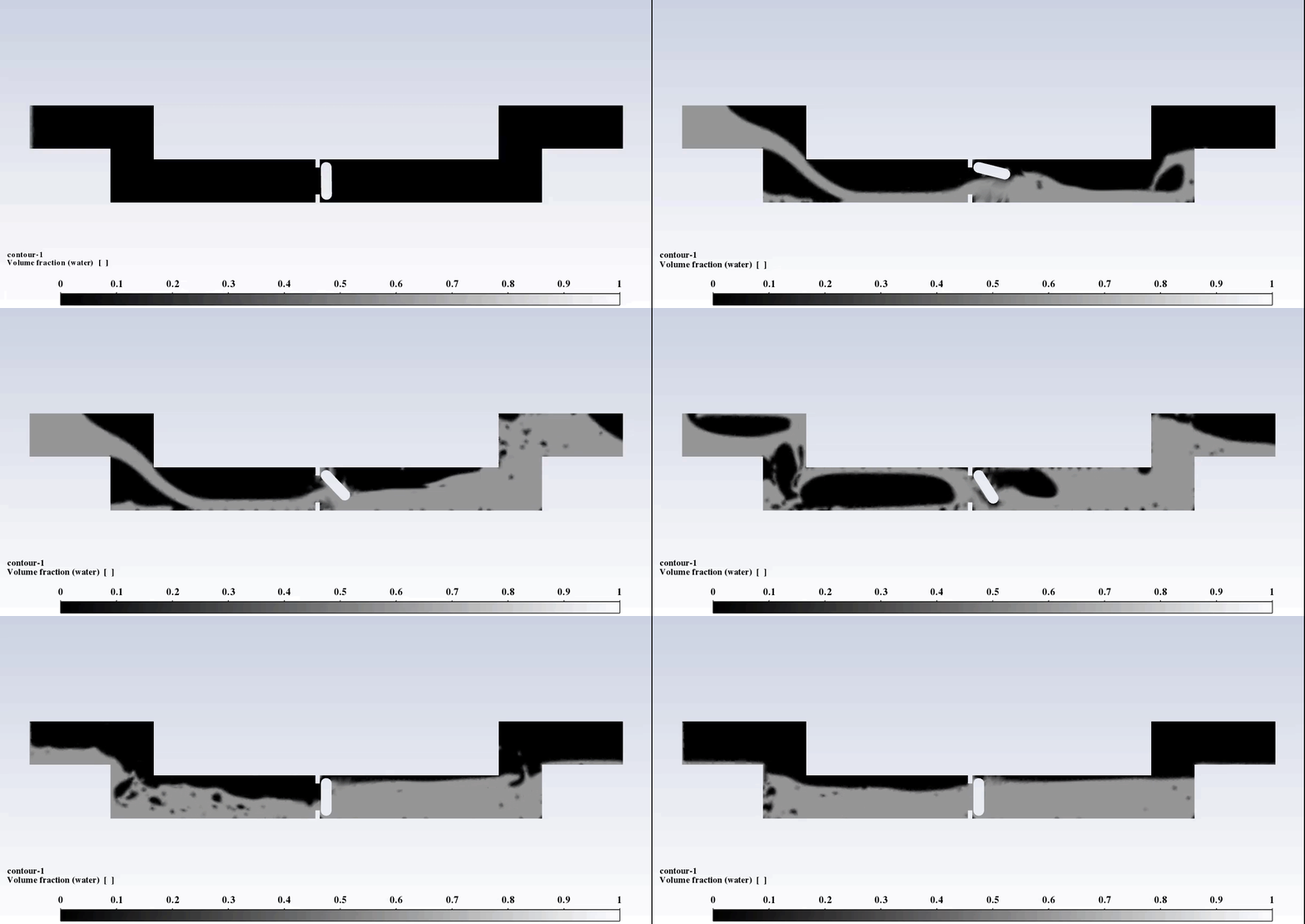
After the solution, we obtained the contour of the mass fraction of water. In addition, we obtained an animation of the mass fraction of water.
The results show that the mechanism of the check valve is working correctly. First, the water flow enters the empty pipe, and applying force to the valve causes the valve to be open.
Then the incoming water flow is cut off. The return water flow by applying force to the valve causes the valve to close.

Ricky Murray I –
What kind of results can we get from the simulation about the check valve functionality?
MR CFD Support –
The results from the simulation allow us to observe the operation of the check valve in real-time. The contours of the mass fraction of water indicate how effectively the valve permits flow in one direction and restricts it in the opposite. The animation of the mass fraction of water delivers a visual understanding of the valve’s response to the flow of water and its successful operation as it opens to allow water to pass and closes when the flow is interrupted.
Natasha Ziemann –
What material properties are used for the check valve in the simulation?
MR CFD Support –
The material properties for the check valve, which includes structural parameters like density, Young’s modulus, and Poisson’s ratio are calibrated within ANSYS Fluent to accurately simulate its rotational motion under the influence of water flow. Factors such as rigidity and buoyancy would also be significant, ensuring the proper function of the valve in the simulation.
Shayne Lockman –
After stopping the water flow, how quickly does the check valve close in the simulation?
MR CFD Support –
The closing time of the check valve after the water flow is stopped might depend on various factors including water momentum, pressure changes, and the physical properties and dimensions of the check valve system. This specific detail is not provided in the summary, so to give you an accurate timeframe would require reviewing the results data of the simulation.
Sabryna Schimmel PhD –
After the water flow is cut off, how long does it take for the valve to close fully?
MR CFD Support –
The simulation provides an animation which demonstrates the valve operation, including closing time. It will show exactly how the fluid forces act on the valve to close it as the flow reverses. The exact closing time would depend on the forces exerted by the reversing flow, valve dynamics, and the inertia of the valve itself. Please check the animation provided with your simulation results for the precise closing timing in your specific case.
Mr. Guiseppe O’Hara –
I’m really impressed with how this training showcases the dynamic behavior of the check valve using CFD. The methodology seems well thought and robust. It’s crystal clear how the example can help understand the complex interaction between fluid and moving parts within a pipe system.
MR CFD Support –
We greatly appreciate your kind words and are thrilled that our Check Valve Dynamic Mesh training course exceeded your expectations. Understanding the intricate dynamics of fluid-structure interaction is at the core of our teachings, and we’re delighted to hear we could convey these complex concepts effectively. Your satisfaction with our training materials motivates us to continue delivering high-quality educational content. Thank you for choosing MR CFD as your learning partner!
Prof. Jesus Hartmann –
The explanation was really detailed. Loved learning about how the check valve operates and the use of dynamic mesh to simulate its movement!
MR CFD Support –
Thank you for your kind words! We are thrilled to hear that you loved the detailed explanation about the check valve and the dynamic mesh simulation. Our goal is to provide comprehensive learning materials that are both informative and engaging. If you have any further questions or need additional learning resources, feel free to get in touch!
Ericka Ward –
I really enjoyed learning from the Dynamic Mesh Training Course with the Check Valve CFD Simulation. The concept of using a dynamic mesh to simulate the movement of the check valve in response to fluid flow was extremely well demonstrated. Watching the valve open when fored by the water flow and then return to close was particularly illuminating and gave me solid insight into dynamic system behavior.
MR CFD Support –
Thank you for your positive feedback! We’re thrilled to hear that our training course enhanced your understanding of dynamic systems and the application of dynamic mesh in simulating the movement of a check valve in fluid flow. Your appreciation encourages us to continue providing high-quality learning materials. Should you have any additional questions or need further clarification in the future, don’t hesitate to reach out. Happy learning!
Mrs. Jenifer Kihn –
The explanation of the check valve simulation is quite detailed, but I’d like to know if gravity was considered within this simulation setup.
MR CFD Support –
Yes, gravity is taken into account in the check valve simulation to ensure that the valve operates under realistic conditions, as gravity can significantly affect the movement of the check valve and the flow of the fluid.
Mr. Jerrod Donnelly V –
The detailed project description is fantastic. Great job on explaining the rationale behind using a dynamic mesh for this simulation. Seeing the valve in action must have been really insightful.
MR CFD Support –
Thank you for your kind review! We’re glad you found the project details and the dynamic mesh application insightful. Watching the check valve in action is indeed fascinating and provides a clear visualization of fluid flow dynamics. Should you have any further questions or need more information on our courses, please feel free to reach out.
Justen Homenick –
The product clearly illustrated the dynamic mesh applied to the check valve system, especially how changes in water flow impacted the valve’s function. It’s intriguing to witness the valve in action in the time-dependent simulations. I appreciate the detail explaining the transition from having a pipe full of air to one where water flows and interacts with the valve.
MR CFD Support –
Thank you for taking the time to write such a positive review! We’re thrilled to hear that the detail of our simulation and our dynamic mesh application in portraying the check valve’s functionality met your expectations. Your enthusiasm for our CFD analysis is greatly appreciated. If you have any further insights or queries, feel free to reach out!
Effie Pfeffer –
I found the Check Valve dynamic mesh simulation from the course fascinating! It seemed complex, but the step-by-step approach made it understandable. Can you advise on how one might extend this project to simulate real-world check valve failures due to wear or debris?
MR CFD Support –
I’m thrilled to hear you enjoyed the Check Valve simulation course! To simulate check valve failures due to wear or particles, you could include additional dynamic conditions in your mesh to represent debris interaction or modify the valve’s physical properties to mimic wear over time. Using a User Defined Function (UDF) in ANSYS Fluent could provide the capability to introduce these complexities into your simulation. It would be crucial to gather realistic data about the wear patterns or the type and flow of debris that typically cause issues in check valves to ensure the simulation accurately reflects real-world conditions.
Kaylah Pagac –
I really enjoyed watching the animation showing the check valve operating! It helped me visualize the flow dynamics perfectly. Great job on the simulation!
MR CFD Support –
Thank you for your kind review! We’re delighted to hear that the animation was helpful and that you were satisfied with the check valve simulation. Visualizing complex dynamics is a crucial part of understanding CFD, and we aim to make these concepts as clear as possible. If you have any further questions or need assistance with future projects, feel free to reach out to us.
Krystina Bartoletti Jr. –
This analysis seems quite complex. Could you elaborate on how the mesh deformation is handled in the zones where there is significant movement? Are there special considerations to prevent mesh errors or distortions?
MR CFD Support –
Absolutely, handling mesh deformation in areas of significant movement is a critical aspect of simulations involving dynamic meshes. ANSYS Fluent employs techniques such as local remeshing and smoothing to manage the mesh. During the simulation, the dynamic mesh model automatically adjusts the mesh in response to the moving boundaries, redefining cells as required. Additionally, users can also set up mesh refinement zones where they anticipate large deformations to occur. Constraints and controlled remeshing parameters are implemented to keep aspect ratios within reasonable limits to prevent mesh errors or distortions that could impact the accuracy of the simulation.
Watson Hudson –
I found the application of the 6-DOF solver and the Execute Command to cutoff water flow particularly interesting. Is the animation of the water mass fraction and valve motion available with the simulation data?
MR CFD Support –
Yes, the animation of the water mass fraction and valve motion is typically included with the simulation data to provide a comprehensive overview of how the check valve operates throughout the process.
Everette Bergnaum –
The description of the motion setup for the check valve dynamic mesh simulation is impressive. I appreciate the technical detail and learned a lot about how the 6-DOF solver allows for a realistic representation of the valve’s motion under fluid forces.
MR CFD Support –
Thank you so much for your positive feedback! It’s fantastic to hear that you found the setup details and the description of the 6-DOF solver implementation educational and helpful. If you have any further questions or need more information, feel free to ask. We wish you the best in your simulation and analysis endeavors.
Mr. Kendrick Ruecker –
I’m thrilled with how the dynamic meshing mechanism simulates the realistic movement of the check valve. It is incredibly helpful to see the transient behaviors and the effectiveness of the valve. Great work!
MR CFD Support –
Thank you for your kind words! We’re delighted to hear our Dynamic Meshing mechanism for the Check Valve simulation met your expectations and proved useful in visualizing its transient behavior. We always strive to offer high-quality, realistic simulations to aid in understanding complex fluid dynamics. Your feedback motivates us to continue delivering products that help our customers. If you have any more questions or need further assistance, please don’t hesitate to reach out!
Elmira Bauch –
I’m curious to know if the fluid-structure interaction (FSI) is considered in this simulation for the check valve operation.
MR CFD Support –
Fluid-structure interaction (FSI) plays a critical role in the operation of a check valve as the fluid forces can alter the valve’s position. In our simulation, the dynamic mesh and 6-DOF solver account for the interaction between the fluid flow and the valve’s movement. We realistically simulate how the valve rotates under fluid forces, capturing the essential aspects of FSI for this type of application.
Dr. Dagmar D’Amore –
Which multiphase model was used in this simulation and what was the purpose of using a multiphase model?
MR CFD Support –
In this simulation, the volume of fluid (VOF) multiphase model was used. The purpose of using the multiphase model was to simulate the interaction between water and air within the pipe. The VOF model allows for tracking of the free surface interface between the two dissimilar fluids, which is necessary to adequately represent the valve dynamics as the water flow is initiated and interrupted within the pipe.
Ms. Salma Klocko –
I’m greatly satisfied with the quality of this dynamic mesh project for simulating a check valve!
MR CFD Support –
We are so pleased that you are satisfied with the quality of our Check Valve CFD Simulation project. Thank you for your kind feedback and for choosing our Dynamic Mesh Training Course!
Davin Willms –
The explanation is pretty advanced. Is it possible to know if this simulation would be suitable for someone just starting with CFD?
MR CFD Support –
For beginners in CFD, this particular project may involve complex concepts such as the dynamic mesh and the valve’s rotational motion using DOF. It is a more advanced project that would require some familiarity with ANSYS Fluent and CFD principles. If you are just starting, you may want to begin with more basic simulations before tackling this one. We have other introductory materials and projects that would be perfect for a CFD novice. Understanding the basics first will make it much easier to progress to more complex simulations like the Check Valve project.
Kathryn Bauch –
Is there a transient study involved and how was the valve motion captured in the simulations? Was the water considered incompressible, and how was it’s behavior modeled during both the opening and closing of the valve?
MR CFD Support –
Indeed, the simulation involved a transient study to capture the valve motion as it is dynamic and changes over time. The motion of the valve is captured using the 6 degrees of freedom (6 DOF) solver to model its rotational movement, while dynamic mesh techniques accommodate the mesh deformation resulting from this movement. The water is considered incompressible, which is a typical assumption for liquid flows at moderate velocities and pressures. The behavior of the water during the opening and closing of the valve is modeled using the volume of fluid (VOF) multiphase model. This allows for the clear depiction of the water and air interface and its interaction with the valve. Transition events such as valve opening caused by water ingress and valve closure due to reverse flow impacting the valve were both dynamically captured using the simulation setup.
Daryl Stroman –
How does the check valve prevent flow in the opposite direction once the inflow is interrupted?
MR CFD Support –
The check valve mechanism operates on a simple principle where the valve allows fluid to flow through it in only one direction. When the flow is introduced in the forward direction, it pushes the valve open. However, upon interruption of inflow, the backflow of the fluid exerts a force on the valve in the opposite direction, prompting it to close. This action of the valve closing prevents the reverse flow of fluid, ensuring unidirectional flow within the pipe.
Jayce Marks III –
Does this simulation indicate what might cause the check valve to fail or not operate as intended?
MR CFD Support –
The simulation focuses on demonstrating the correct operation of the check valve in changing flow conditions. To determine potential failure modes or malfunctions, one would typically conduct a more in-depth analysis including factors such as material fatigue, wear, external influences, and non-ideal fluid behaviors which might be beyond the scope of this CFD simulation.
Trevion Zulauf –
The explanation of the dynamic mesh and the 6 DOF solver in the simulation is really comprehensive. It helps understand the valve’s motion and the flow’s interaction wonderfully.
MR CFD Support –
Thank you for your kind words! We’re delighted to hear that the details provided on the dynamic mesh and the 6-DOF solver gave you a clearer understanding of the check valve simulation process. Your feedback is greatly appreciated, and we’re glad that we could support your learning experience effectively.
Nadia Waelchi –
I had no trouble setting up my simulation by following the check valve tutorial. The animations presented in the results section made understanding the function of the check valve quite intuitive.
MR CFD Support –
Thank you very much for your kind words! We’re delighted to hear that our tutorial was clear and helpful, and that the animations enhanced your understanding of the check valve’s operation. If you have any more questions or require further assistance, feel free to reach out. We’re here to help!
Mrs. Mya Schaefer Sr. –
The check valve simulation was very informative—definitely would recommend MR CFD’s dynamic mesh course to learn fluid dynamics practically.
MR CFD Support –
We are thrilled to hear that our Check Valve CFD Simulation course was helpful to you! Thank you for recommending our Dynamic Mesh Training Course, and we appreciate you taking the time to provide your feedback.
Keyshawn McGlynn –
I found the implementation of the Execute Command for flow interruption very effective. Great job including that specific real-life operational detail in the training.
MR CFD Support –
Thank you! We’re glad to hear that you appreciate the level of detail in our Dynamic Mesh CFD Simulation for the Check Valve training. It’s important to us to provide simulations that are as close to real-life applications as possible for an immersive learning experience.
Florence Collins –
I really loved the dynamic representation of the check valve’s operation! Do the water and air in this simulation interact realistically to depict flow cut-off scenarios?
MR CFD Support –
Thank you for the kind words about our dynamic check valve CFD simulation! Yes indeed, the interaction between the water and air is modeled using the Volume of Fluid (VOF) multiphase model, allowing for a realistic depiction of both fluids’ behaviors. The water flow’s cut-off and return flow scenarios are simulated to demonstrate the check valve’s response, showcasing its correct operation as depicted by the conveyed animation.
Astrid Rodriguez MD –
I found the project fascinating. Not only did it enhance my understanding of dynamic mesh and valve mechanisms, but the visualizations were well executed. Great job!
MR CFD Support –
Thank you for your kind words! We’re thrilled to hear that you found the Check Valve CFD Simulation project insightful and that it added to your knowledge of dynamic mesh models. If you have further inquiries or need assistance with similar projects, feel free to reach out. We love helping our customers achieve a deeper understanding of fluid dynamics simulations.
Deshawn Connelly PhD –
I’m really impressed by how the dynamic meshing handles the check valve movement! Can you tell me what kind of post-processing results that are included in the learning materials? Do we get to see flow visualization around the moving parts?
MR CFD Support –
The post-processing results included in the learning materials feature a detailed visualization of the flow. This typically includes the contour of the mass fraction of water and an animation showcasing the motion of the water and the operational mechanics of the check valve. You will be able to see how the force of the water opens and then closes the valve, providing a clear understanding of the valve mechanics under fluid force.