Cylinder Piston Motion CFD Simulation, Dynamic Mesh
$120.00 Student Discount
- The problem numerically simulates the Cylinder Piston Motion using ANSYS Fluent software.
- We design the 2-D model with the Design Modeler software.
- We mesh the model with ANSYS Meshing software, and the element number equals 16,623.
- We perform this simulation as unsteady (Transient).
- We use the Dynamic Mesh Model to define deforming and moving zones.
- We use the In-Cylinder option to define the reciprocating motion of the piston inside a cylinder.
- We use the in-build function called full-piston to define the movement of the piston surface.
- We use the Profile to define the intake and exhaust valve lift.
To Order Your Project or benefit from a CFD consultation, contact our experts via email ([email protected]), online support tab, or WhatsApp at +44 7443 197273.
There are some Free Products to check our service quality.
If you want the training video in another language instead of English, ask it via [email protected] after you buy the product.
Description
Description
This project is related to the numerical simulation of the Cylinder Piston Motion using ANSYS Fluent software. Suppose we have a four-stroke engine. So we will move with four steps. The rotational movement of the crankshaft is transmitted to the piston through the connecting rod, creating a vertical reciprocating motion of the piston in the cylinder. Now, this reciprocating movement includes four stages.
This product is the second chapter of the Dynamic Mesh Training Course.
First, the piston inside the cylinder moves down. Simultaneously, the intake valve opens, and flow enters the cylinder.
Second, the piston rises to compress the flow inside the cylinder.
Third, the piston reaches the highest possible point (top dead center) for the explosion to occur.
Finally, the piston inside the cylinder moves down again. At this step, it is time to open the exhaust valve to direct the resulting flow out.
We do not intend to investigate chemical reactions, combustion, or explosion in this simulation. We want to model the reciprocating motion process of the piston in the cylinder.
We modeled the geometry of the project using Design Modeler software. The geometry is related to the cylinder and piston. The computational domain of the model includes the interior of a cylinder, where a piston is placed at the bottom, and two intake and exhaust paths with valves are placed on top of it. Then we meshed the model with Ansys Meshing software. The model mesh is unstructured, and the number of cells equals 16,623.
Cylinder Piston Motion Methodology
In this project, we used the Dynamic Mesh Model. We generally use a dynamic mesh whenever we have a moving boundary or a deforming zone. Here, a piston surface has a transitional motion inside a cylinder. So this causes the mesh to deform over time. Therefore, we define the In-Cylinder option to define the reciprocating motion of the piston inside a cylinder.
In the in-cylinder model, we determine parameters such as crank radius, connecting rod length, piston stroke cutoff, etc. Using the parameters we defined, the Fluent software defines an in-build function called full-piston. We use this full-piston function to define the movement of the piston (that is, the boundary of the piston).
Now, we must define the reciprocating motion of the piston surface and intake and exhaust valves. We have to define the boundary related to the piston surface and valves as a rigid body; so that we define motion for these rigid bodies.
To define the movement of the piston surface, we use the function of the full piston. But to define the movement of intake and exhaust valves, we use profiles that describe the changes in valve lift in terms of crank angle.
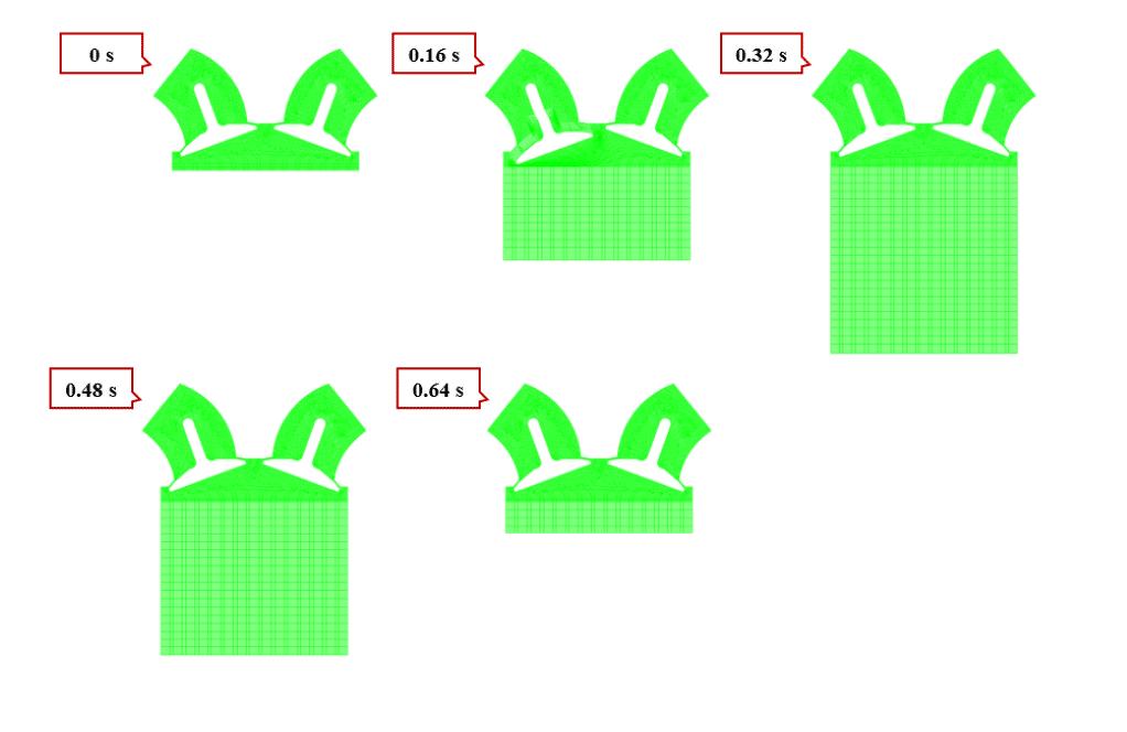
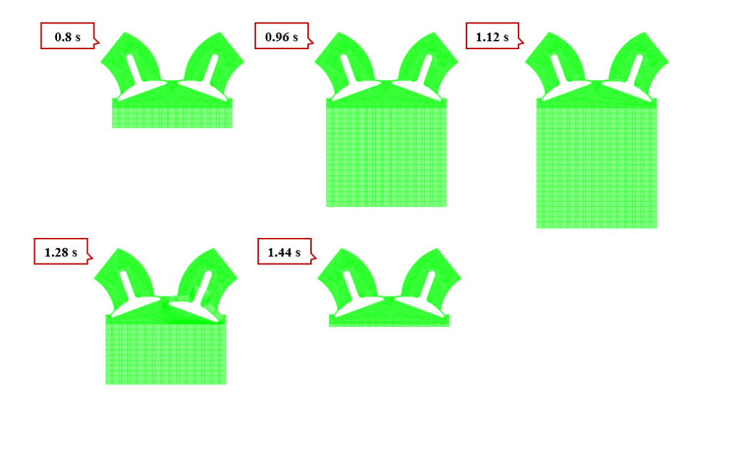
According to the reciprocating motion of the piston and valves as rigid bodies, the mesh zone inside the cylinder is deformed. So, for this zone, we use the Deforming option. Input and output paths are not affected by mesh changes. So for these areas, we use the stationary option.
Due to the nature of this modeling, flow behavior is time-dependent. Hence, we use the unsteady (Transient) solver.
Conclusion
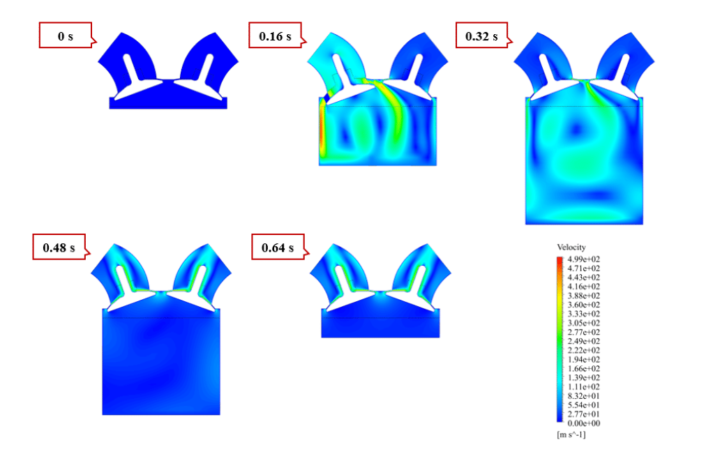
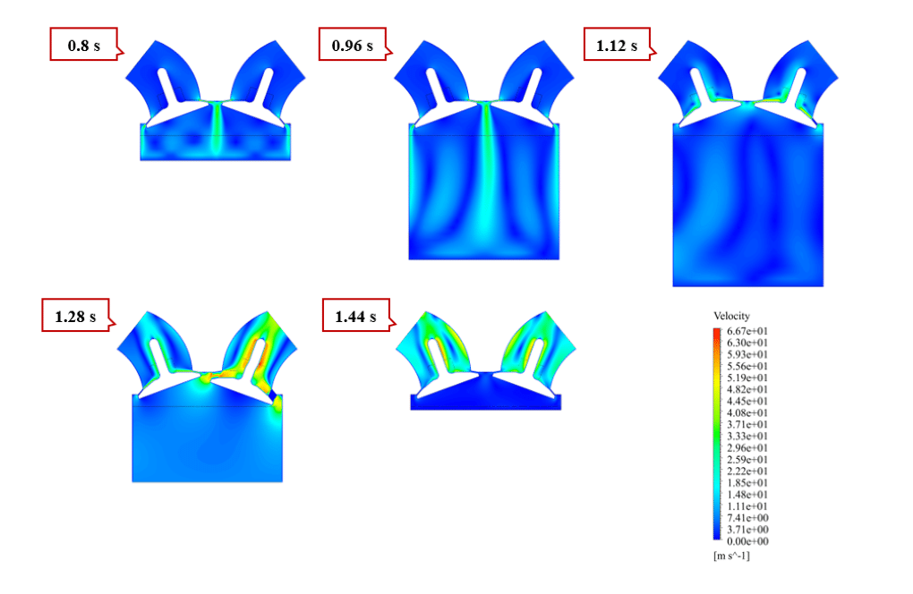
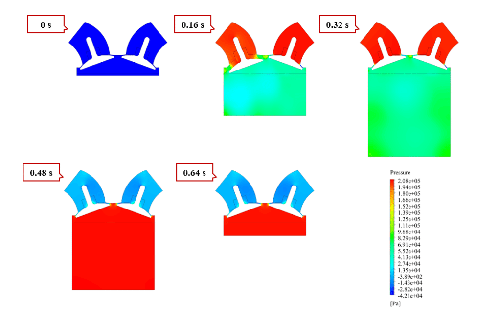
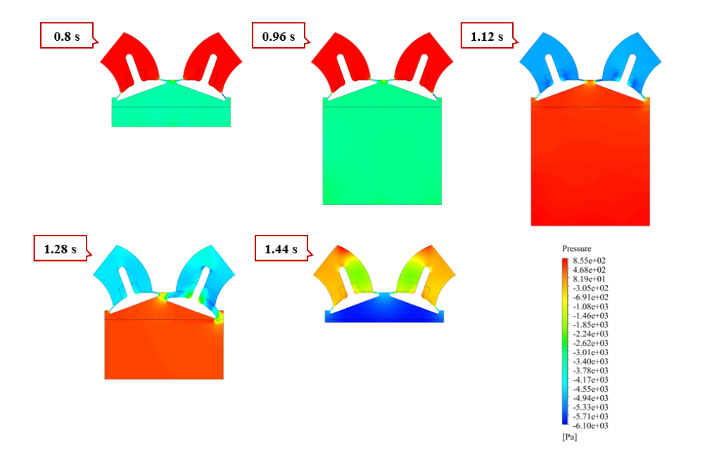
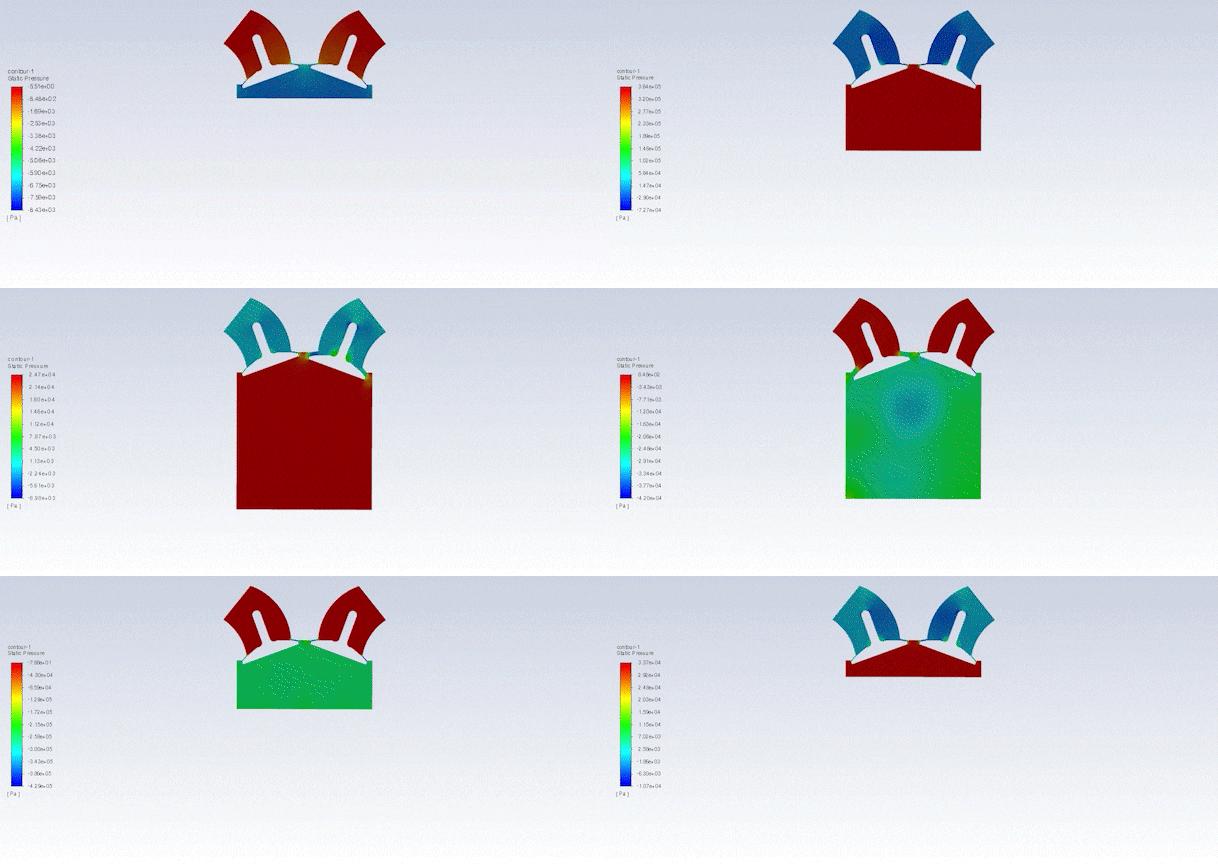
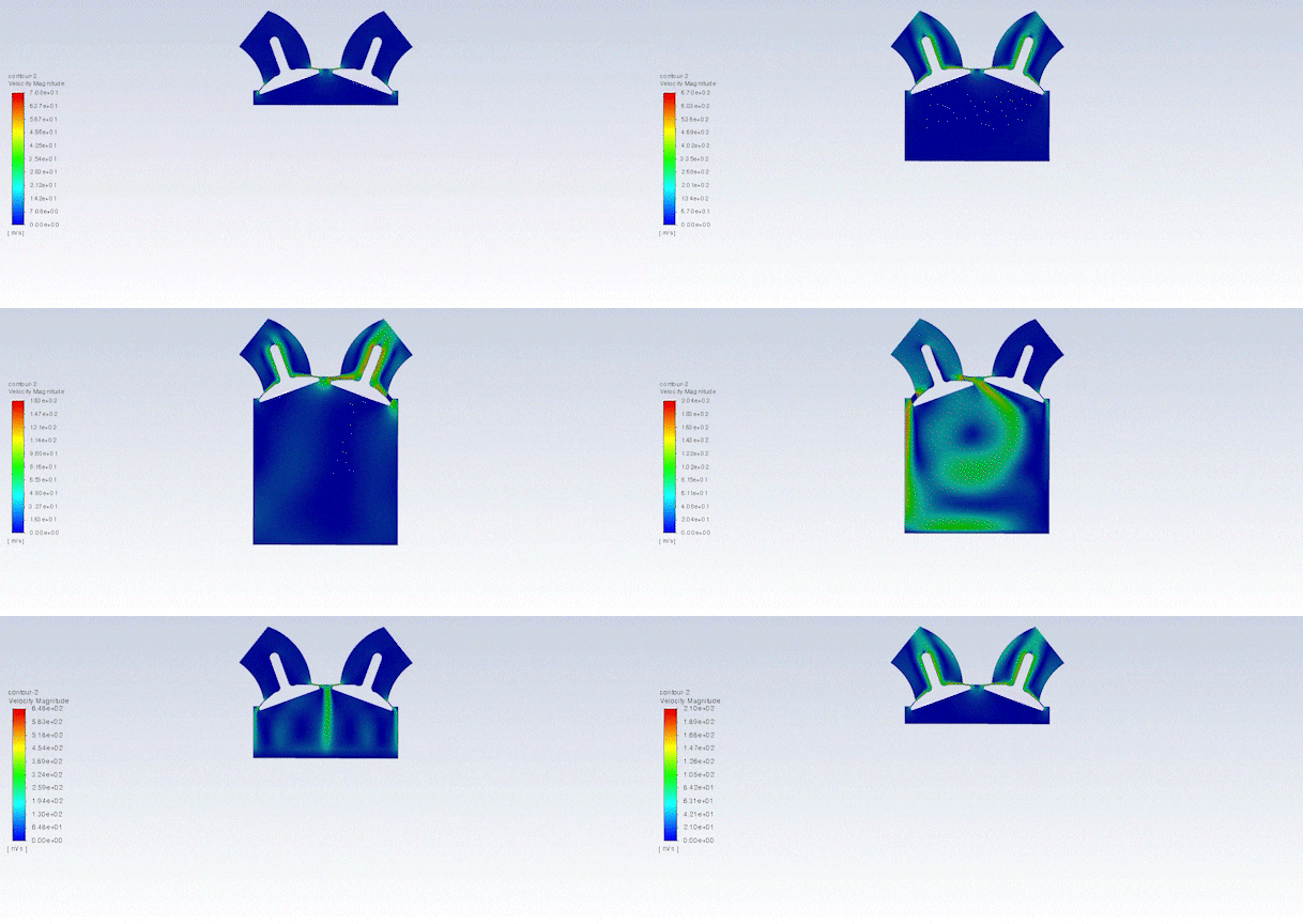
After the solution, we obtained pressure and velocity contours. In addition, we obtained an animation of velocity and pressure contours.
The results show that the cylinder-piston system is working correctly. The piston surface constantly moves up and down over time. Also, the intake and exhaust valves are opened and closed in turn and sync with the piston motion.
Finally, we got an animation of momentary mesh changes.


Prof. Guy Wintheiser –
I was impressed with the meticulous dynamic mesh setup for the piston motion simulation. It seems like precise parameters are key for accuracy. Could you elaborate on the level of detail required when specifying input for functioning elements like crank radius and connecting rod length?
MR CFD Support –
Thank you for your positive feedback! Indeed, the level of detail is crucial in these simulations. Accurate specification of input parameters, such as crank radius and connecting rod length, is imperative to closely simulate the mechanical behavior of the engine components. These inputs must be defined with high accuracy to ensure that the simulated motion reflects the real-world performance and to obtain reliable CFD results.
Dr. Leonard Kihn I –
The training course provided a comprehensive understanding of dynamic mesh in ANSYS for simulating cylinder-piston motion. The clear steps and animated results made it easy to grasp the concepts. Thoroughly enjoyed learning from MR CFD’s course and the hands-on experience it offered!
MR CFD Support –
Thank you for your positive feedback! We are thrilled to hear that our Dynamic Mesh Training Course has helped you understand the complex concept of simulating cylinder-piston motion in ANSYS Fluent. Your satisfaction with our course encourages us to continue providing high-quality learning products. If you have any further questions or need more assistance, don’t hesitate to reach out!
Ms. Aliyah Lehner –
The animation of the mesh changes during the simulation really helped visualize the process. Well done on creating such dynamic content
MR CFD Support –
Thank you for your compliment! We’re thrilled to know that the animation added clarity to the understanding of the dynamic mesh and the piston motion. It’s gratifying to see our effort in creating immersive and informative content is appreciated. If you have any more feedback or need further assistance, feel free to reach out!
Elliott Gottlieb –
This dynamic mesh analysis seems comprehensive. Well done! Can you tell me how the mesh deformation was handled when the piston is moving within the cylinder?
MR CFD Support –
The dynamic mesh changes accommodating the piston’s movement are managed by Fluent’s Dynamic Mesh Model. Within this model, we use ‘Deforming’ for the mesh zone inside the cylinder. This option updates the mesh continually as the rigid piston moves. The function defining piston motion determines how the piston surface and adjacent mesh adapt throughout the piston’s reciprocating motion.
Mr. Caleb Rutherford –
Very impressed with how effectively the Dynamic Mesh Model captured the piston and valve movements in the simulation. The contour results and animation are clear and comprehensive, truly reflecting the real-world four-stroke engine behavior.
MR CFD Support –
On behalf of everyone at MR CFD Company, we truly appreciate your kind words about our Dynamic Mesh Model product. It’s wonderful to hear that the clarity and comprehensive outcomes of the simulation contributed to your understanding of engine behavior. Your feedback is incredibly valuable to us, and we look forward to continually serving our customers with high-quality, informative simulations. Thank you for choosing our learning products and taking the time to leave a positive review!
Gilbert Koss PhD –
Amazing level of detail in the product! The simulation captures the dynamics of an engine cylinder with impressive accuracy. The animations were particularly helpful in visualizing the complex motion and the changes in the mesh.
MR CFD Support –
Thank you for the positive feedback! We’re thrilled to hear that our simulation provided the clarity and detail you needed for understanding the intricate motions within an engine cylinder. It’s great to know our animations were able to effectively visualize the concepts for you.