Contra-Rotating Turbine CFD Simulation Training
$140.00 Student Discount
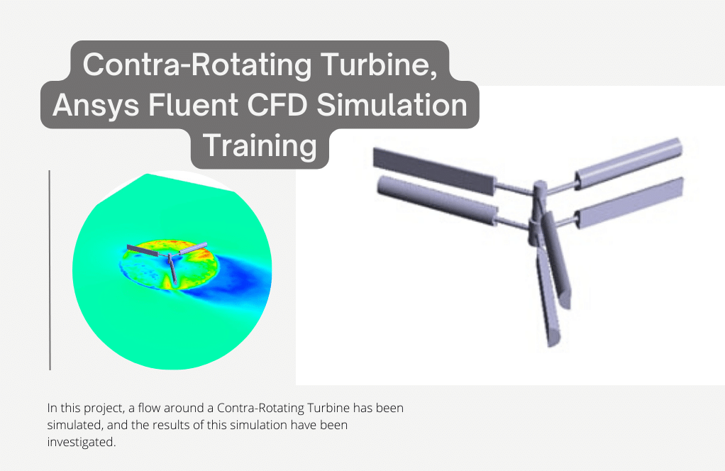
In this project, a flow around a Contra-Rotating Turbine has been simulated, and the results of this simulation have been investigated.
Click on Add To Cart and obtain the Geometry file, Mesh file, and a Comprehensive ANSYS Fluent Training Video.To Order Your Project or benefit from a CFD consultation, contact our experts via email ([email protected]), online support tab, or WhatsApp at +44 7443 197273.
There are some Free Products to check our service quality.
If you want the training video in another language instead of English, ask it via [email protected] after you buy the product.
Description
Contra-Rotating Turbine, Ansys Fluent CFD Simulation Training
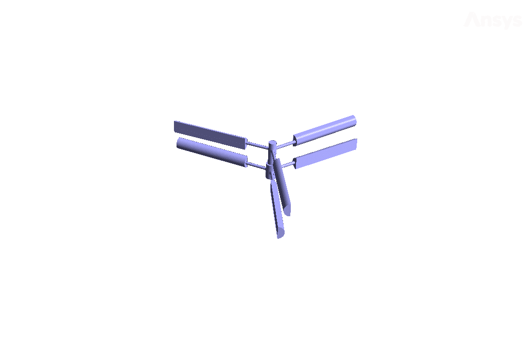
The present simulation is about a contra-rotating VAWT turbine via ANSYS Fluent. The contra-rotating turbine is an axial flow turbine with two rows of blades, So these two rows of blades rotate with equal rotational speed but in opposite directions. Contra-rotating turbines recover energy and power loss due to airflow through the front row of blades.
In other words, using two rows of rotating blades in opposite directions doubles the turbine’s torque power.
In this simulation, the mesh motion method defines the rotational motion of air.
In this model, two rows of blades are designed. A distinct zone for airflow is defined in the vicinity of each of these rows. Then, for each of these two zones, mesh motion is used. The rotational velocity of both rows of blades is defined as 14.7 rad.s-1; But these two areas’ central axis of rotation is defined in opposite directions.
The airflow around the upper blades rotates clockwise, and the lower row blades rotate counterclockwise. Also, the inlet airflow velocity to the computational domain is defined as 5.3 m.s-1.
Geometry & Mesh
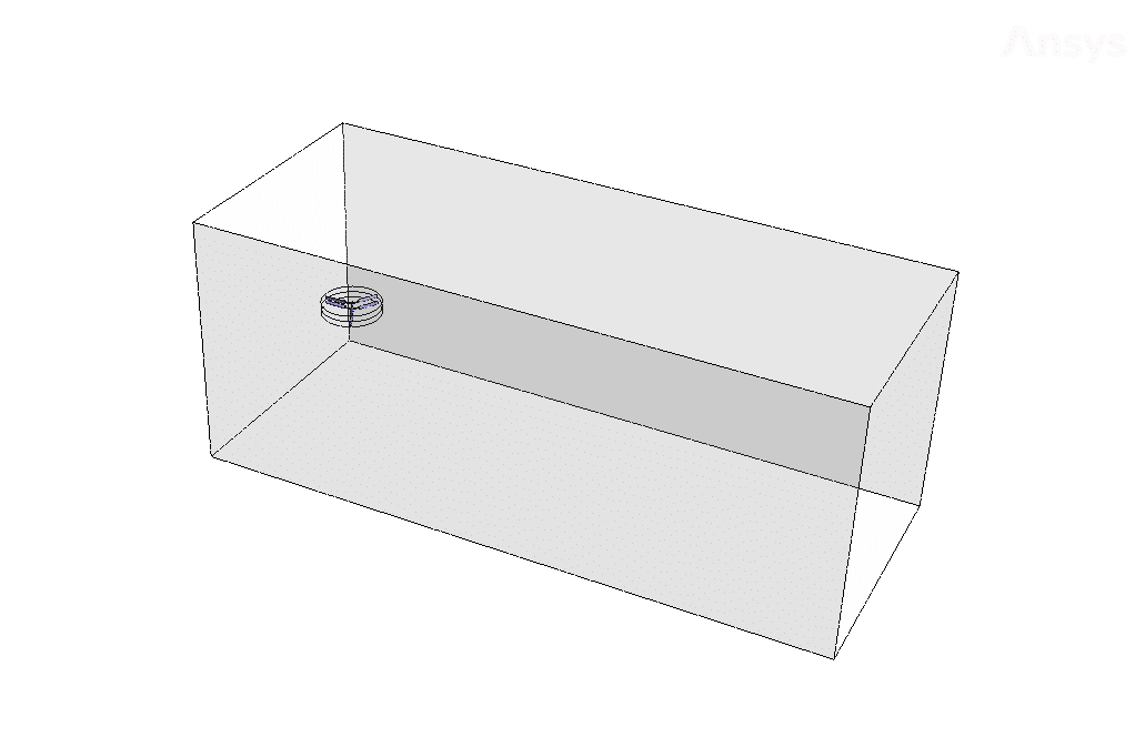
The present geometry is designed in a 3D model via Design Modeler. This model includes a rectangular cube computational domain with two rows of blades connected in parallel in the middle. Each row of blades has three blades.
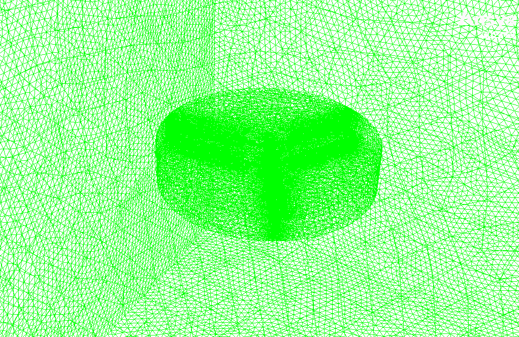
The mesh of the present model has been done via ANSYS Meshing. Mesh is done unstructured, and the number of production cells is equal to 3747546.
Set-up & Solution
Assumptions used in this simulation :
- pressure-based solver is used.
- The present simulation is steady.
- The effect of gravity is ignored.
| Models | ||
| Viscous | k-epsilon | |
| k-epsilon model | standard | |
| Near-wall treatment | standard wall function | |
| Boundary conditions | ||
| Inlet | Velocity Inlet | |
| velocity magnitude | 5.3 m.s-1 | |
| Up & Down Blades | Wall | |
| wall motion | stationary wall | |
| Outlet | Pressure Outlet | |
| gauge pressure | 0 pascal | |
| Symmetry | Symmetry | |
| Methods | ||
| Pressure-Velocity Coupling | SIMPLE | |
| pressure | Second-order | |
| momentum | First-order upwind | |
| turbulent kinetic energy | First-order upwind | |
| turbulent dissipation rate | First-order upwind | |
| Initialization | ||
| Initialization methods | standard | |
| gauge pressure | 0 pascal | |
| x-velocity | 5.3 m.s-1 | |
| y-velocity & z-velocity | 0 m.s-1 | |
Contra-Rotating Turbine Results
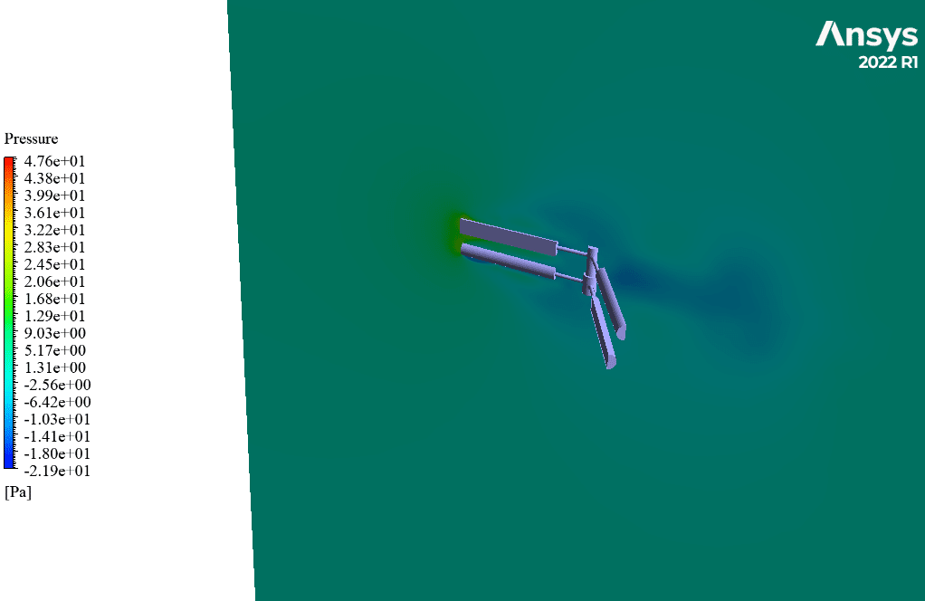
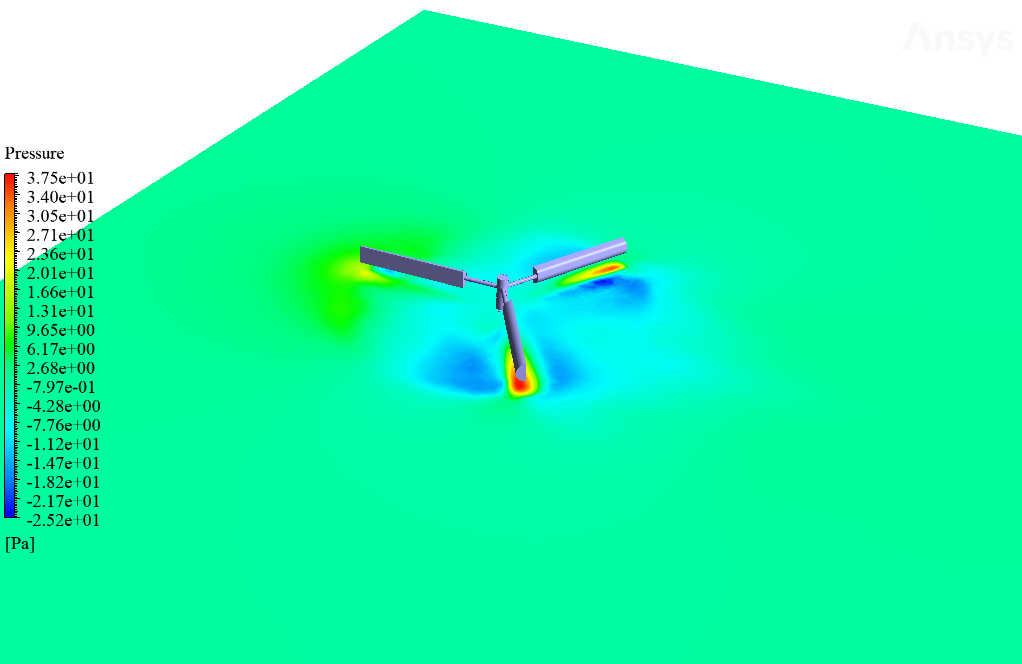
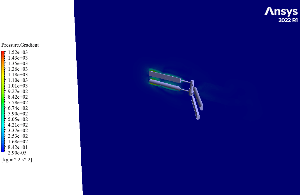
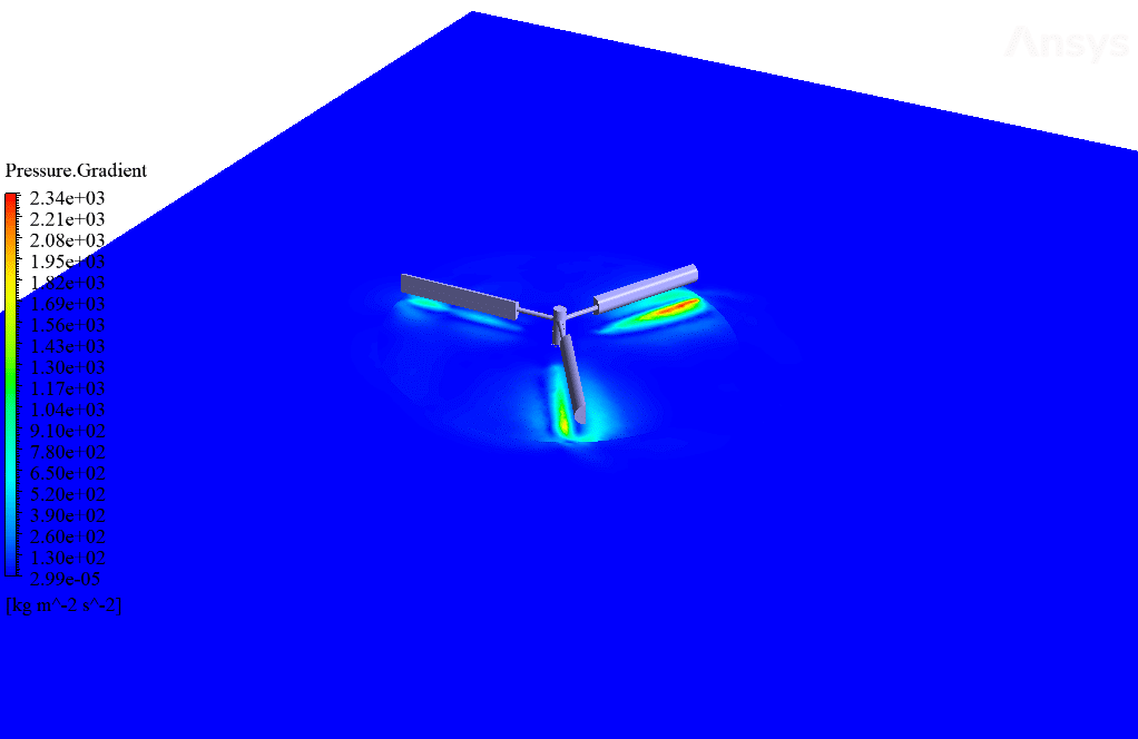
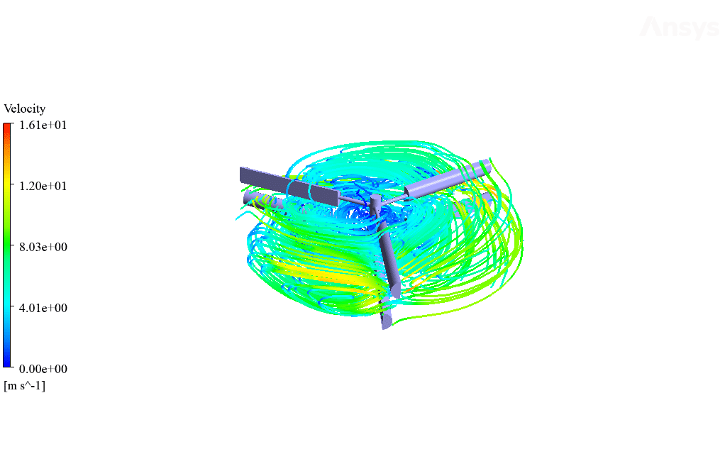
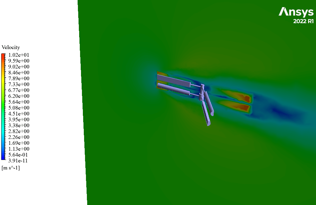
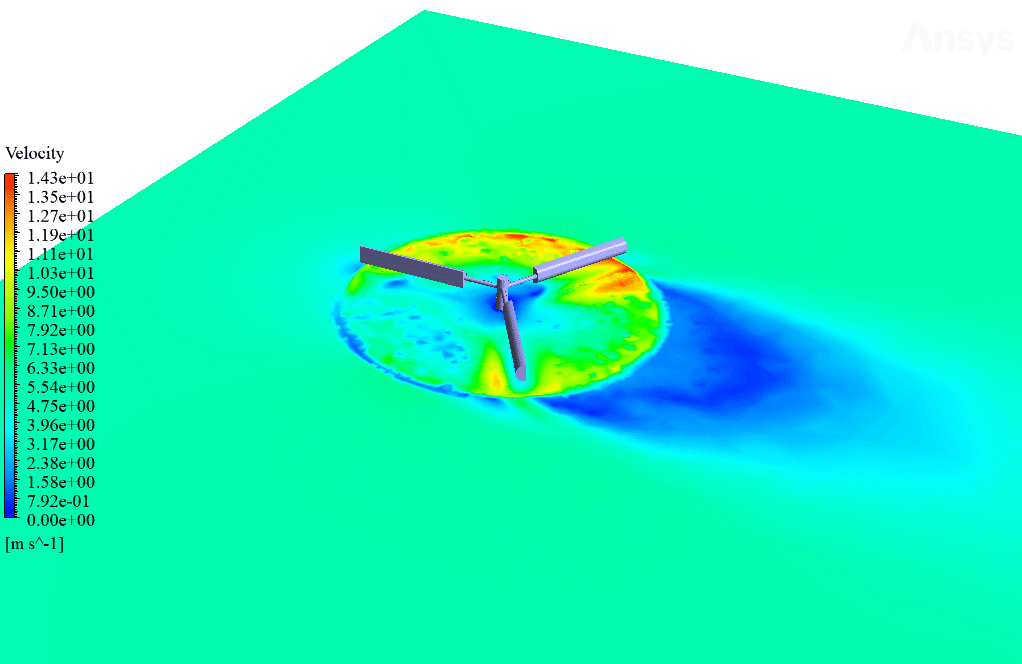
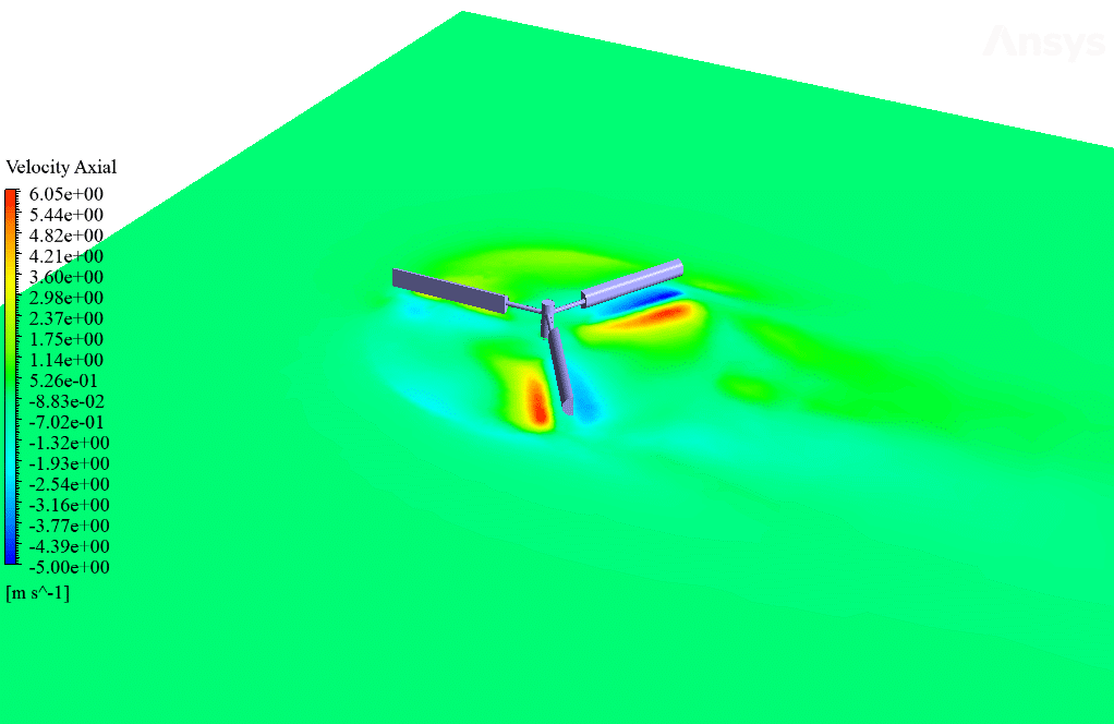
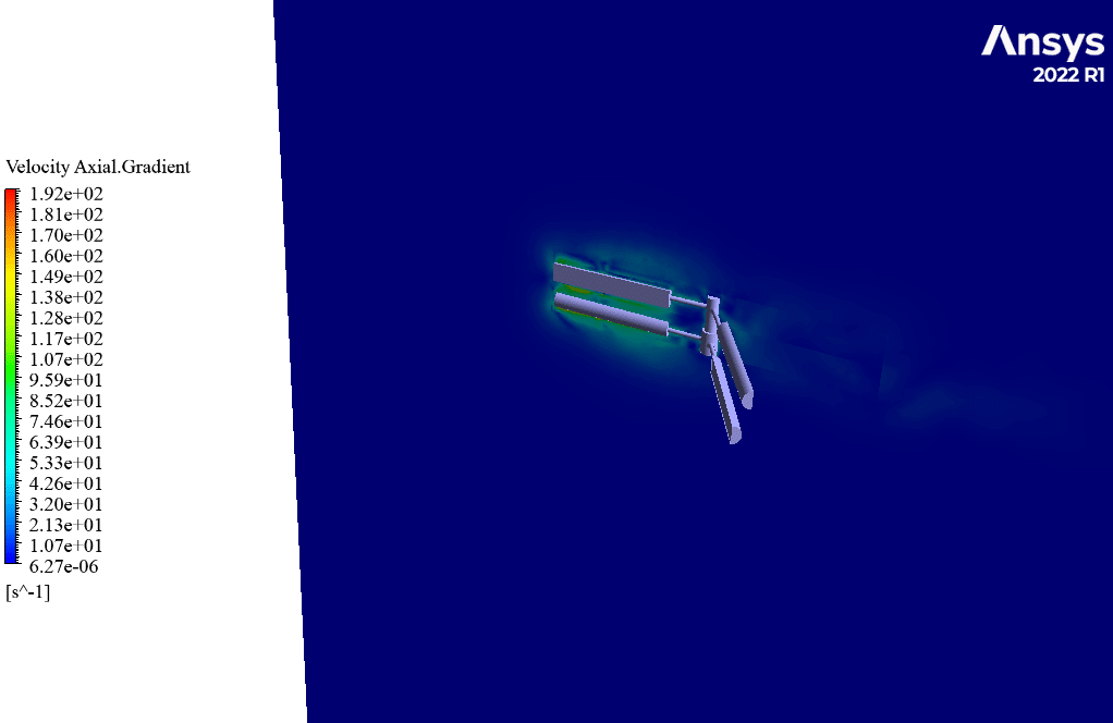
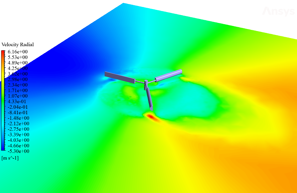
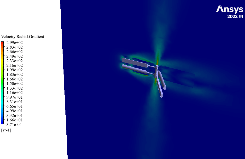
After simulation, streamlines and 2D contours related to velocity, pressure, and velocity and pressure gradients are obtained. The contours show that pressure and velocity in the space between the two rows of turbine blades increase, and, as a result, the value of torque and power applied to the turbine blades is enhanced.
Also, the value of torque applied to the upper blades (clockwise) is equal to 1.89 N.m, and the value of torque applied to the lower blades (counterclockwise) is equal to 1.93 N.m. Therefore, in this turbine model, approximately equal torque is applied to each row of blades.
Arlene Schuppe –
The training was fantastic, extremely detailed and easy to stretch to parallel applications. Remarkable to see the torque balance between the upper and lower blades — exemplifies the clr design efficiency perfectly. Gold standard tutorial here!
MR CFD Support –
Thank you for your positive feedback and recognition of the details in our Contra-Rotating Turbine CFD Simulation Training. We’re delighted to hear about your successful experience with the tutorial and the applicability of the design principles you’ve learned. Your comments motivate us to continue delivering high-quality education materials!
Wilbert Rodriguez –
Fantastic training set! The details about the mesh motion, boundary conditions, and the outcome showing the increase in torque and power were clear and very informative. It’s great to see how the contra-rotating design efficiency gets highlighted with actual CFD simulation data. Would love to see more simulations like this for other turbine models.
MR CFD Support –
Thank you for your positive feedback! We’re thrilled to hear that you found the training resource informative and helpful for understanding the efficiency gains provided by the contra-rotating turbine design. We certainly look forward to bringing more high-quality simulations for other models in the future.
Haylie Schmidt –
I was impressed with the unique approach of using contra-rotating blades. Could you explain how using these blades doubles the turbine’s torque in comparison to traditional blade setups?
MR CFD Support –
In a contra-rotating turbine, the second row of blades utilizes the airflow slipstream from the front row to recover some of the available energy that would typically be lost. Thus, by ensuring the second row rotates in the opposite direction, it counteracts the rotational wake from the first, recovering more energy and translating it into additional rotational torque. Essentially, it’s like getting a second ‘bite at the cherry,’ leading to the doubling of the torque generated for the same airflow compared to a single set of blades.
Vaughn Schneider –
I couldn’t find if the 3D contours of flow structures, like vortices, were also included in the results. Are they presented with the contra-rotating turbine simulations?
MR CFD Support –
No explicit mention of 3D contours of flow structures like vortices is made in the product description. However, since it mentions obtaining streamlines and 2D contours related to velocity and pressure, it appears that these vital flow features can be visualized and analyzed through available simulation data.
Holly Greenholt –
I’m really interested in how the coupled torque results get processed. Could you possess in-depth info regarding the practical applications of this simulation? Looks highly promising for sustainable energy solutions!
MR CFD Support –
Thank you for your kind words. In practical applications, analyzing the torque on both sets of blades in such detailed simulations is essential to optimize turbine design for maximum efficiency. Accurate torque measurements allow engineers to improve the design and positioning of the blades for enhanced energy capture from the wind. The data from this simulation can guide enhancements in real-world turbines, leading to higher performance and more sustainable energy solutions.
Humberto Block MD –
The training for contra-rotating turbines seems impressively thorough. I’m curious, does it include a comparison with single-rotation turbines in terms of performance improvements?
MR CFD Support –
In our Contra-Rotating Turbine CFD Simulation Training, we focus on the detailed operation and benefits of contra-rotating turbines. While we do highlight how the torque power doubles by using two rows of blades, the training primarily discusses the specifics of the contra-rotating model itself. It may not directly compare single-rotation turbines, but the improvement in performance is implied by the detailed results of torque and power enhancement featured in the simulation.