Ducted Fan: Noise and Thrust CFD Study, ANSYS Fluent
$180.00 Student Discount
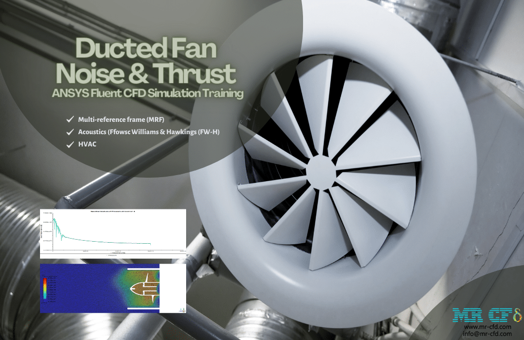
- The present CFD project simulates a ducted fan employed in a room via ANSYS Fluent software.
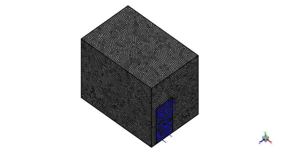
- We have designed the geometry using ANSYS Design modeler software and created the mesh on this geometry using ANSYS meshing software. The mesh type is Polyhedra with 699432 cells.
- multi-reference frame (MRF) model simulates the rotational treatment of the fan.
- Ffowsc-Williams & Hawkings (FW-H) model determines the acoustic effects.
To Order Your Project or benefit from a CFD consultation, contact our experts via email ([email protected]), online support tab, or WhatsApp at +44 7443 197273.
There are some Free Products to check our service quality.
If you want the training video in another language instead of English, ask it via [email protected] after you buy the product.
Description
Description
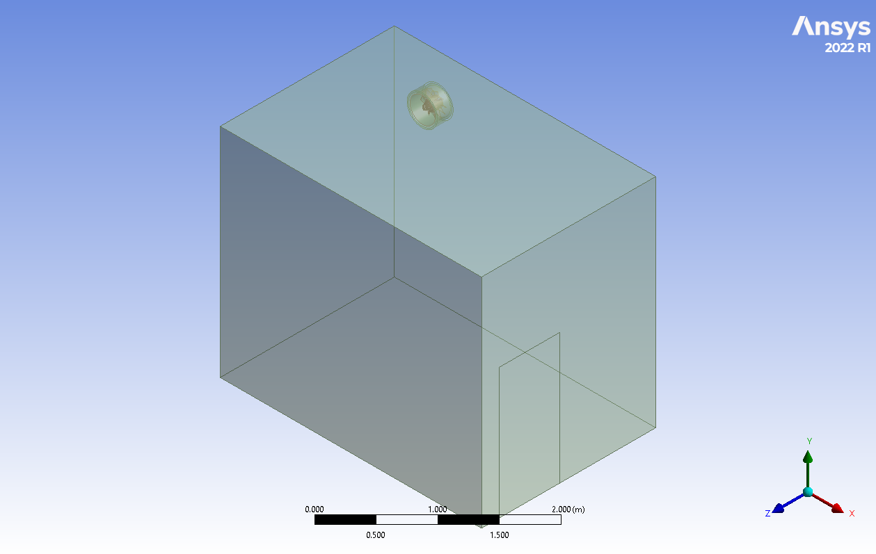
The present project simulates a ducted fan employed in a room. The study aims to investigate the acoustic condition & performance. There is a flow inlet from the door with 0.5 m/s velocities. Also, an outlet on the wall where the ducted fan is implemented. The fan is rotating with 1000 rpm angular velocity.
The 3D model is designed in Ansys Design Modeler software. A 2*3m rectangular room with 2.5-meter height and a 30cm in diameter fan. Moreover, the mesh grid is carried out in Ansys Meshing software. In the first step, a tetrahedron mesh grid is generated; then converted to Polyhedra elements to reduce the number of elements and computational cost. In total, 699432 elements are generated.
Methodology: Ducted Fan Noise & Thrust
The gravitational acceleration is considered in the negative direction of the Y direction by 9.81 m/s^2. The k-epsilon realizable model is used in order to capture the foreseeable wakes and turbulence. In addition, a separated zone is defined for the fan to apply Frame motion (MRF) and Ffowsc Williams & Hawkings (FW-H) Acoustic model determines the acoustic effects.
Conclusion
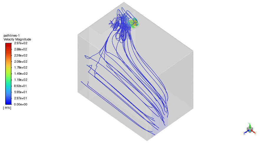
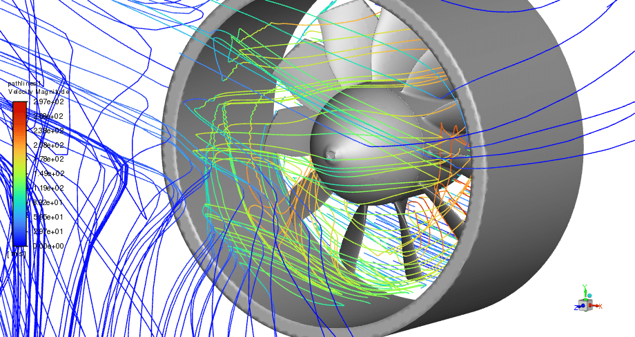
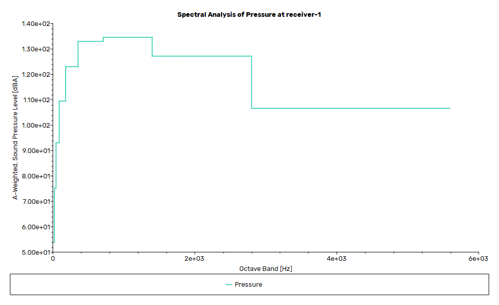
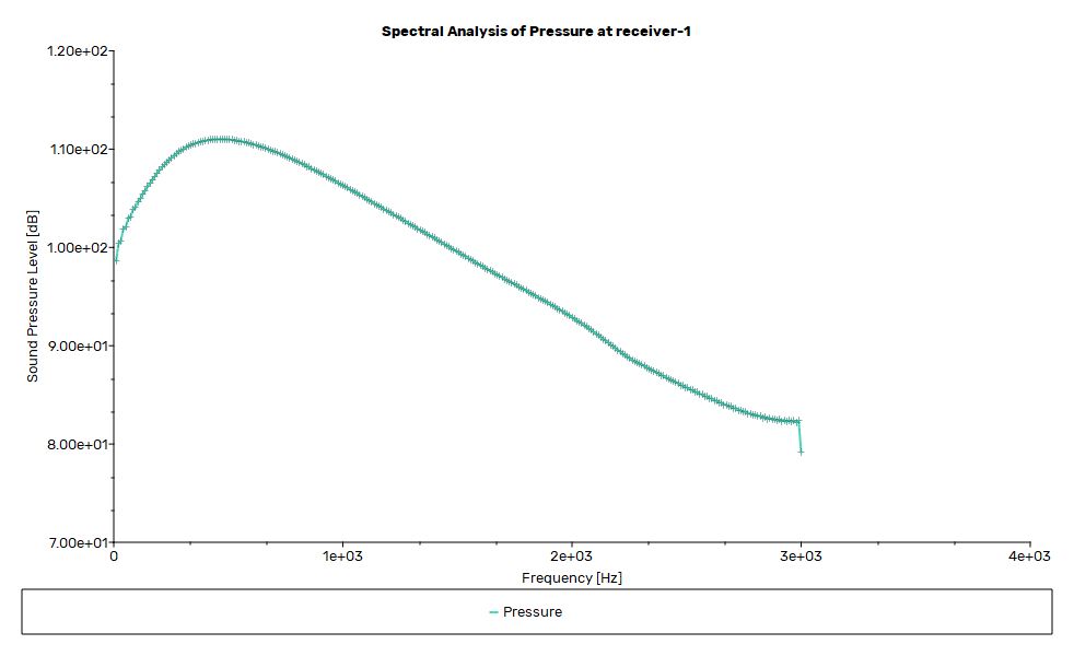
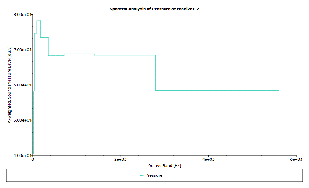
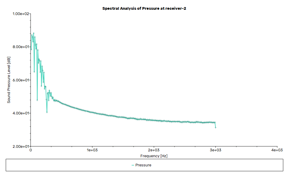
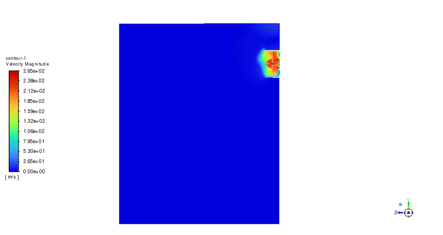
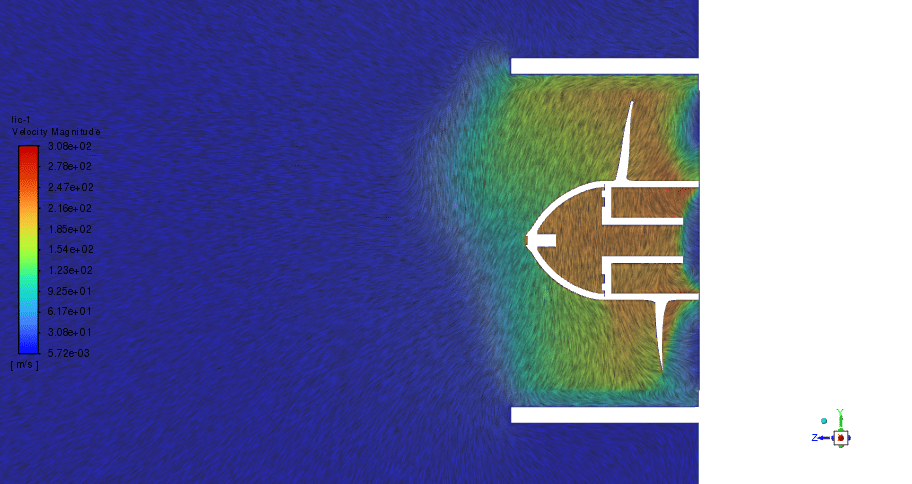
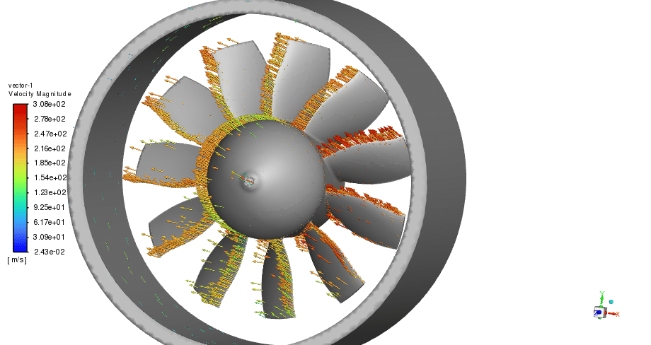
Two sound receivers are located in the room to investigate the noise effect of the fan. One is in front of the fan(receiver 1) and the other one at the entrance, near the door (reciever2). As seen in the contours, air enters the domain with 0.5 m/s, forms wake around the fan zone, and then leaves the domain. Furthermore, the duct acts like a silencer and limits the sound distribution.
Hence, although the sound pressure level is high in receiver 1, it is an acceptable range near receiver 2 that won`t cause any problem for the residents. The A-weighted pressure level backs up the claim and shows 80 dB at its maximum point, less than 120dB. After all, the thrust force is reported as 54.113455N.

Chelsie Jast –
The product description is excellent and detailed. I’m curious about how different speeds of the fan might affect the noise level. Could you provide a brief insight into whether higher or lower fan speeds would significantly impact the recorded sound pressure levels?
MR CFD Support –
Increasing the fan speed will generally lead to higher sound pressure levels due to increased airflow turbulence and mechanical operation noise. Conversely, running the fan at a lower speed is likely to reduce noise levels. For precise quantification of these effects at various speeds, additional simulations would be necessary.
Prof. Josh Hyatt –
It’s clear a lot of thought went into this simulation of the ducted fan. I am impressed with the detailed methodology describing how gravity was accounted for and how the FW-H Acoustic model was deployed to assess noise impacts within the room. The sound pressure levels’ conclusions are reassuring, particularly the mention that the noise remains within acceptable limits for residents.
MR CFD Support –
Thank you for recognizing the details and efforts that went into this study. We always aim to provide thorough analyses to ensure our simulations are as realistic and applicable as possible for our clients. Your feedback is important to us, and we’re delighted to hear that the outcomes of the acoustic study were satisfactory to you. We appreciate you taking the time to leave such a positive review!
Trudie Beatty –
I’m impressed by the reduction of sound distribution thanks to the duct acting as a silencer. It’s quite fascinating to learn how this setup keeps the acoustic conditions in check. Especially noteworthy is how the A-weighted pressure level is at a comfortable range, ensuring a pleasant environment for the residents. Amazing work in utilizing both acoustic modeling and airflow analysis for practical, comfort-considerate solutions!
MR CFD Support –
Thank you for your positive feedback! We’re thrilled to hear that you found our study on the ducted fan both fascinating and informative. Our team is dedicated to delivering detailed and practical simulations that have real-world applications. Knowing that our work contributes to improving living environments is deeply satisfying. If you have any more insights or need further information, we’re always here to help!
Lelah Bayer –
Can this simulation help to design quieter cooling solutions for residential applications?
MR CFD Support –
Absolutely! The study of ducted fans in different configurations and the application of the Ffowsc Williams & Hawkings (FW-H) Acoustic model provide valuable insights into the acoustic performance. This information is vital for designing quieter fans and cooling systems suitable for residential applications.
Prof. Hester Mueller –
I’m impressed with this project’s focus on reducing noise effects. Does the simulation account for different sound frequencies or only overall dB levels?
MR CFD Support –
The simulation takes into account different sound frequencies using the Ffowcs Williams & Hawkings (FW-H) Acoustic model. It reports the A-weighted pressure level which assesses the noise levels at various frequencies according to how the human ear perceives sound.
Mr. Camron Larkin III –
The acoustic simulation provided insights about the sound levels. Could you please explain if the thrust force determination equally takes room acoustics into consideration, or is it solely based on aerodynamic calculations?
MR CFD Support –
Thrust force calculation in this simulation primarily relies on aerodynamic computations involving the movement of air around and through the ducted fan. The acoustic models are separate and are used to evaluate sound propagation and intensity in the room, but they do not directly affect the thrust force determination.