Fan Stage (Axial Flow) Aerodynamic Performance, ANSYS Fluent Training
$100.00 Student Discount
- The problem numerically simulates Fan Stage (Axial Flow) Aerodynamic Performance using ANSYS Fluent software.
- We design the 3-D model by the Design Modeler software.
- We Mesh the model by ANSYS Meshing software, and the element number equals 757886.
- We use the Frame Motion model to define rotational motion.
To Order Your Project or benefit from a CFD consultation, contact our experts via email ([email protected]), online support tab, or WhatsApp at +44 7443 197273.
There are some Free Products to check our service quality.
If you want the training video in another language instead of English, ask it via [email protected] after you buy the product.
Description
Description
This project simulates steady airflow in a 3D axial flow fan stage using ANSYS Fluent software. We perform this CFD project and investigate it by CFD analysis.
The present model is designed in 3-D using the Design modeler. The model consists of a rotating zone and a stationary zone.
The meshing of this present model has been generated by ANSYS Meshing software. The total cell number is 244675.
Fan Stage Methodology
In this project, steady airflow in a 3D geometry of the fan stage is simulated by ANSYS Fluent software.
A fan stage is a common apparatus used for creating steady airflow in industrial applications used in the cooling process of newly painted body parts. The periodic boundary condition simulates the real fan stage at the lowest computational cost.
Two sections are involved Rotor and Stator. The rotor, which has a built-in blade, rotates with constant angular velocity and leads air to enter the stator region with high velocity. Blade within stator alters the flow direction to force it exit stator approximately normal to outlet surface.
Rotor domain rotation is simulated using the MRF module with an angular velocity equal to 1800rpm. The stator domain is fixed.
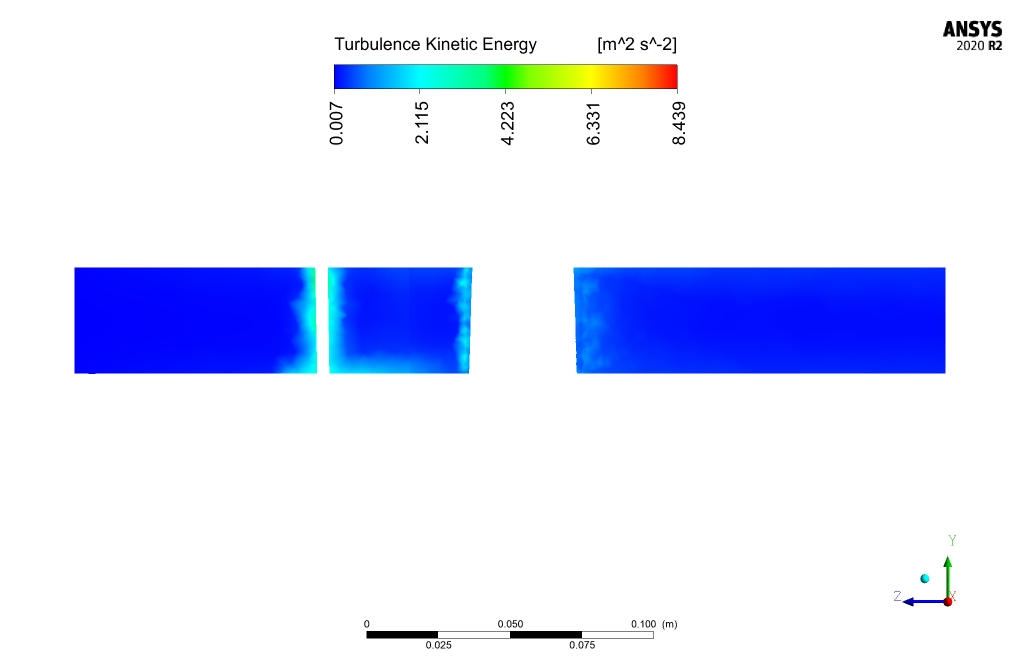
Moreover, the standard k-epsilon model is used to solve the turbulent fluid flow equations.
Fan Stage Conclusion
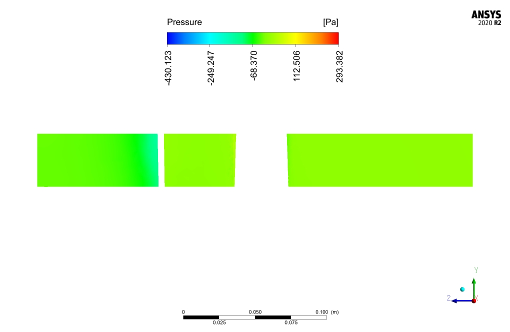
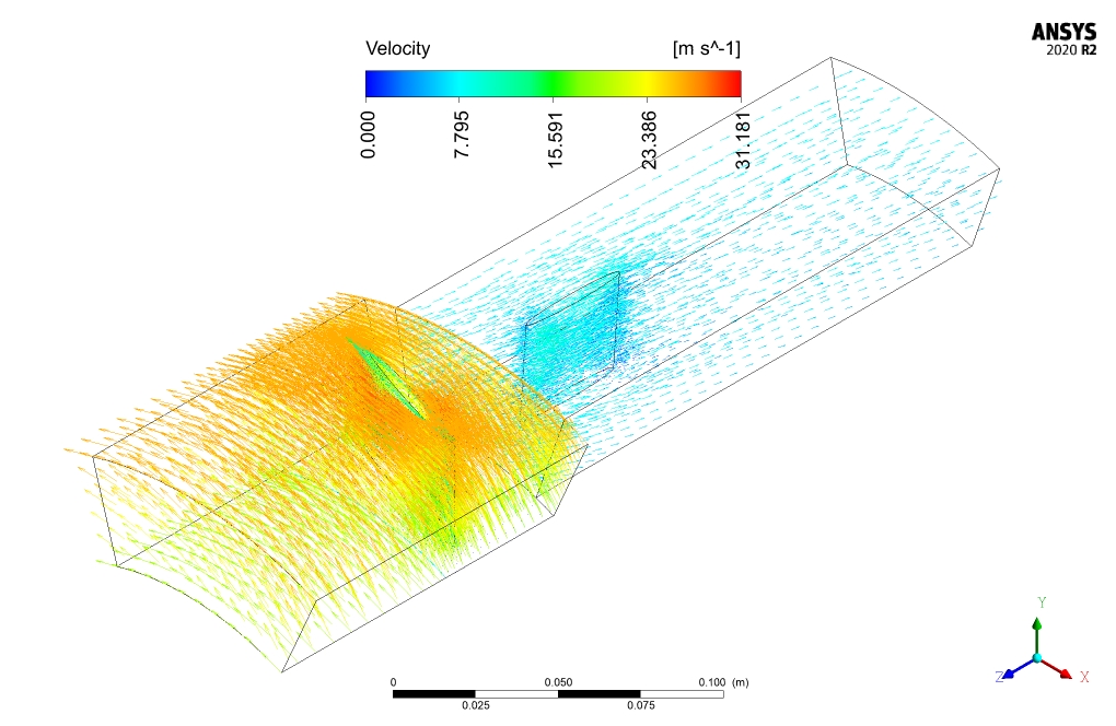
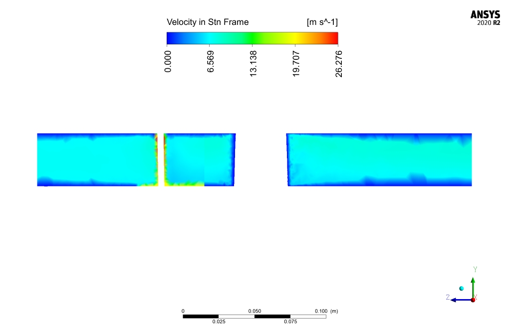
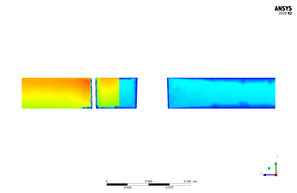
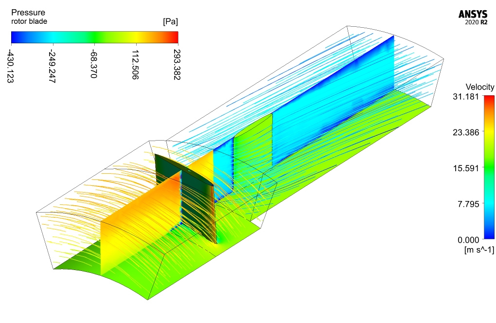
After the simulation, two- and three-dimensional results related to pressure, velocity, streamlines, and velocity vectors are obtained. For instance, as seen in streamlines and velocity vectors results, the rotating motion of the fluid due to the rotation of the rotor domain is clear.
Furthermore, based on the data calculated using Fluent, the rotor’s angular velocity of 1800 rad/s results in linear velocity of the max diameter of the rotor equal to 31 m/s.
TSR (Tip Speed Ratio), which is the ratio of angular velocity (=32m/s) to free stream flow velocity in the stator (=8m/s), is equal to 4. The airflow rate at the stator outlet is equal to 16.14 lit/s.



Izaiah Hodkiewicz –
Can the simulation be used to analyze the performance of fan stages at high angles of attack?
MR CFD Support –
Yes, the simulation can be used to analyze the performance of fan stages at high angles of attack. Please contact us with your specific requirements.
Rickey Kreiger –
Can this simulation be extended to model transient aerodynamic scenarios?
MR CFD Support –
Yes, this simulation can be extended to model transient aerodynamic scenarios. We are open to contributions and can accommodate your desired simulations.
Leland Quigley –
How does the simulation account for the effects of compressibility?
MR CFD Support –
The simulation accounts for the effects of compressibility using the ideal gas law, which is a common approach for modeling compressible flows in CFD.
Timmothy Boyle –
The training and methodology seem solid. The step-by-step explanation is great and helps understand how the velocity and flow direction is influenced by the rotor and stator.
MR CFD Support –
Thank you for your positive feedback about our ANSYS Fluent training for the Fan Stage (Axial Flow) Aerodynamic Performance simulation. We’re glad to hear the step-by-step explanations were helpful to you. If you have any further questions or need more details, we’re always here to assist you!
Laverna Bosco –
I am thoroughly impressed with your explanation of the operations of the rotor and stator in an axial flow fan stage. The reliance on the periodic boundary condition truly illustrates the sophistication of computational techniques for optimizing resource management. Detailing RPM alongside linear velocities grants a clear insight into system performance. And a TSR (Tip Speed Ratio) of 4 furnishes a concise assessment of the interaction between angular and free stream flow velocities. Your learning product has evidently fostered a deep understanding of fluid flow processes in fan stage mechanisms.
MR CFD Support –
We are delighted to know that you have found our ANSYS Fluent training on axial flow fan stage simulations insightful and helpful. It’s rewarding to see that the detailed operational principles and the comprehensive explanation of the model’s performance have enhanced your understanding of aerodynamic performance in industrial applications. Thank you for your affirmative feedback; it’s much appreciated!
Alessandra Heathcote –
The conclusion on axial aerodynamic performance was illuminating. Learning how various parts of the fan work in tandem through simulation was quite interesting. This clearly shows the possibilities with CFD and ANSYS Fluent!
MR CFD Support –
Thank you for your positive review. We are thrilled to hear that our Fan Stage Aerodynamic Performance project provided valuable insights into axial fan operation and the capabilities of ANSYS Fluent. Your acknowledgement is truly appreciated. If you have any more interest in CFD studies or need further assistance, feel free to reach out!
Ms. Telly Aufderhar –
I appreciate the clear explanation of how you’ve utilized the MRF module to simulate the rotor’s motion. I found your simulation a great learning tool to understand the aerodynamics of fan stages!
MR CFD Support –
Thank you for your positive feedback! It’s great to hear that the simulation was helpful and provided you with a clear understanding of fan stage aerodynamics. We’re glad you found our training material effective for learning. If you have any more questions or need further assistance, feel free to reach out.
Carlee Kuhn –
This training project seems excellent for understanding fan stages. Can you elaborate on the significance of the TSR (Tip Speed Ratio) and its practical applications in industry?
MR CFD Support –
The Tip Speed Ratio (TSR) is a critical dimensionless parameter that describes the efficiency of a fan, wind turbine, or compressor’s blade design. It is the ratio of the speed of the blade at its tip to the speed of the airflow it’s encountering. In practical applications, a well-chosen TSR for a fan or turbine ensures optimal energy extraction from the air, maximizing performance while minimizing undesired effects such as noise and wear. The TSR in industrial situations is geared towards improving performance efficiencies, maintainability, and lifespan of the device.
Marcelle Hegmann –
The Fan Stage CFD simulation training course by ANSYS Fluent truly enhanced my understanding of axial flow in an industrial context. The detailed explanation of using MRF for the rotor zone and clear demarcation of rotor-stator interactions was excellent. The course also adeptly covered the implementation of turbulence models, enriching my insight into complex flow phenomena. Brilliant job!
MR CFD Support –
Thank you for your kind words! We’re delighted to hear that our Fan Stage (Axial Flow) Aerodynamic Performance, ANSYS Fluent Training helped to deepen your understanding of axial flow and the rotor-stator dynamics. We strive to provide clear and comprehensive training courses, and we’re glad this was reflected in your learning experience. If there’s anything more we can assist you with, feel free to reach out!
Larry Thiel III –
Is the TSR value of 4 within typical ranges for fan stages? What implications might this have on performance?
MR CFD Support –
In the simulation of the axial flow fan stage, the Tip Speed Ratio (TSR) was found to be 4. Typically, TSR values can vary widely depending on the specific design and application of the fan. A TSR of 4 suggests that the rotor’s tip is moving faster than the incoming airflow. This may imply that the fan is efficient in accelerating the air and could be indicative of good performance. However, without comparing this value to those typical for similar fan stage designs, it is challenging to make definitive statements. Ideal TSR values also differ based on the fan’s application and desired outcomes, such as noise reduction, energy efficiency, or maximum airflow.
Carlo O’Conner –
The fan stage simulation looks very comprehensive. I learned a lot from the methodology! Could we simulate different rotational speeds for the rotor, to see the effect on the efficiency of the fan?
MR CFD Support –
We’re delighted to hear you’ve benefitted from our fan stage methodology. Yes, various rotational speed for the rotor can indeed be simulated to analyze their effect on the fan’s performance and efficiency. If you’d like to explore these variables further, you may consider utilizing parameter study features within ANSYS Fluent to streamline this process systematically.
Marjorie Schuppe –
The ANSYS Fluent training on Aerodynamic Performance of Fan Stage sounds thorough and practical. Really appreciated the details on rotor and stator interactions and the use of MRF module for rotation simulation.
MR CFD Support –
Thank you for your positive feedback! We’re delighted to hear that the training was informative and met your expectations. It’s great to know that the details provided on rotor-stator dynamics and the application of the MRF module were genuinely appreciated. If you have any further questions or need assistance with similar simulations, feel free to reach out. We are here to help!
Rick Little –
Amazing course on aerodynamic performance analysis! The lessons on setting up rotational simulations using the MRF model were clear and informative. The examples used made learning about TSR in the context of fan stages really valuable for my studies.
MR CFD Support –
We greatly appreciate your positive feedback! It’s fantastic to hear that our course helped enhance your understanding of aerodynamic performance in fan stages and that the rotating simulations techniques were effectively explained. Thank you for choosing our training for your learning needs.
Dr. Freddie Rowe –
I was really impressed with the seamless integration of rotor-stator interaction in simulating the aerodynamic performance of the fan stage. The details were well-explained, and the use of MRF for the rotating zone helped clarify the rotational influences on airflow. Great job on showcasing the step-by-step procedure and final results!
MR CFD Support –
Thank you for your positive feedback! We’re thrilled to hear that the training provided clarity and a thorough understanding of rotor-stator interactions in axial flow fan stages. Your appreciation makes our efforts worthwhile. If you need further information or have more questions, feel free to reach out.
Coralie Hills –
I’ve learned a lot from this course! The practical approach to simulating the fan stage with both the rotor and stator dynamics was incredibly informative. It was fascinating to see how the airflow is influenced by the rotor speed and how the blades alter the flow direction. Great job on providing detailed insights into the aerodynamic performance!
MR CFD Support –
Thank you for your kind words! We’re thrilled to hear that the course on simulating the fan stage was invaluable to you. It’s always great to hear that our customers are not only satisfied with their learning experience but are also gaining practical insights into complex simulations. We look forward to providing you with more enriching and informative content in the future!
Miss Brittany Reinger –
I’m really pleased with how well the training demonstrated the axial fan simulation, especially how TSR is calculated. Great job on illustrating complex concepts in such an accessible way!
MR CFD Support –
Thank you for your kind words! We’re glad that you found the training helpful and that it effectively demystified the calculation of Tip Speed Ratio and other aerodynamic elements. Your feedback is appreciated!
Dr. Ross Rosenbaum –
I learned so much about simulating airflow in axial fans through this training! The details on how to set up the simulation using ANSYS Fluent were clear and the methodology section was particularly helpful. Nicely done!
MR CFD Support –
Thank you for the positive feedback! We’re delighted to hear that you found the training on axial flow fan stages helpful and informative. If you have any further questions or need more assistance, don’t hesitate to reach out. We’re here to help!
Sheldon Powlowski –
I just finished the Axial Flow Fan Stage training, and I must say it’s fantastic! The step-by-step process clearly highlighted each part of the simulation, and watching the interplay of forces in the rotor and stator was quite enlightening. The MRF approach for modeling the rotating domain was well taught—it makes me appreciate the complexity behind designing an efficient fan stage.
MR CFD Support –
We’re thrilled to hear that you enjoyed the Axial Flow Fan training! It’s awesome that you found the step-by-step instruction clear and enlightening. Understanding the complexity of fan stage design is crucial, and we’re glad that our product could assist in your learning journey. Thank you for your positive feedback, and if you ever have any questions or need further assistance, we’re here to help!
Thora Schmeler –
Extremely well-executed simulation! The technical aspects were thoroughly addressed, and I found the investigation of aerodynamic performance within the axial flow fan stage truly comprehensive. The use of the periodic boundary condition for cost-effective and realistic simulation was a smart choice that piqued my interest. Integration of the MRF module for rotor simulation indeed reflects an advanced understanding of moving reference frame mechanics and its necessity in rotatory motion analysis. The clarity of the results is commendable as they evidently showcase the influence of rotor motion on airflow patterns. Could you confirm if post-processing included noise level evaluation for industrial applicability, or was it focused solely on aerodynamic performance metrics?
MR CFD Support –
Thank you for your valuable feedback and detailed compliment on our axial flow fan stage simulation product. Noise level evaluation is an essential factor in industrial applications. However, our simulation was primarily focused on investigating the aerodynamic performance, such as pressure distribution, velocity profiles, streamlines, and efficiency metrics like Tip Speed Ratio (TSR). If you’re interested, we can certainly explore noise and vibration analysis as additional aspects in a dedicated simulation product for comprehensive insights into fan stage performance in all relevant areas.
Meghan Brakus –
I’m impressed by the detailed results and simulations accomplished in the aerodynamic evaluation of the axial flow fan stage. The use of the standard k-epsilon model and MRF module clearly provides robust data for industrial applications. It’s intriguing to see how the rotational speed of the rotor heavily influences the airflow characteristics in the stator region. Great job visualizing the effects with the streamlines and velocity vectors!
MR CFD Support –
Thank you for your kind comments! We’re thrilled to hear that our simulation for the aerodynamic performance of the fan stage met your expectations. It’s particularly satisfying to know that the visualization of the airflow and the comprehensive data were of such interest and utility to you. We appreciate your feedback and are glad that our product provided the insights you needed.
Jovanny Abernathy –
I was impressed with the level of detail in the fan stage simulation results! The inclusion of streamlines and velocity vectors really helped visualize the airflow.
MR CFD Support –
Thank you so much for your positive feedback! We’re really glad to hear that the results of the fan stage simulation were able to provide you with a clear visualization of the airflow. It’s gratifying to know that the quality and depth of the CFD analysis have met your expectations. If you have any more inquiries or need further assistance, feel free to let us know!