Fish Cage Floating on Seawater CFD Simulation by FSI Method, ANSYS Fluent
$330.00 Student Discount
- The problem numerically simulates Fish Cage Floating on Seawater using ANSYS Fluent software.
- This project is performed by the fluid-structure interaction (FSI) method.
- We design the 3-D model by the Design Modeler software.
- We Mesh the model by ANSYS Meshing software, and the element number equals 4922130.
- We perform this simulation as unsteady (Transient).
- We use the Dynamic Mesh method to consider grid changes over time.
- We apply the System Coupling to communicate between Fluent and Transient Structural software.
- We use the VOF Multi-Phase model to define the two-phase flow, including water and air.
To Order Your Project or benefit from a CFD consultation, contact our experts via email ([email protected]), online support tab, or WhatsApp at +44 7443 197273.
There are some Free Products to check our service quality.
If you want the training video in another language instead of English, ask it via [email protected] after you buy the product.
Description
Description
The present problem simulates a fish cage floating on seawater’s surface using the Fluid Solid Interaction (FSI) method in ANSYS Fluent software. We perform this CFD project and investigate it by CFD analysis.
The present model is designed in three dimensions using Design Modeler software. The model includes a computational domain with seawater and airflow and a circular fish breeding cage within this domain.
Due to the fact that the model has a perfectly symmetrical structure, half of the model is designed to reduce the computational cost. This computational area has a section called input and a section called output, and the lateral faces of this area have symmetry conditions.
The meshing of the model has been done using ANSYS Meshing software, and the element number is 4922130.
Also, a transient solver has been enabled due to the nature of FSI problems.
Fish Cage Methodology
Due to the fact that this fish breeding cage is floating within the computational area, the flow of seawater collides with this cage, and as a result, two-way interaction between fluid and solid must be considered. Therefore, we should apply the FSI method in the ANSYS Workbench software environment.
When using the FSI method, due to the change in the structure of the fluid flow mesh around the geometric model, it is necessary to define a Dynamic Mesh. The dynamic mesh technique allows changing the mesh structure of the model in a time-dependent manner.
In determining the dynamic mesh method, we apply Smoothing and Remeshing methods. To define two-way FSI, System Coupling should be used in ANSYS Workbench software.
To perform the system coupling, the model must first be defined in each Fluent and Transient Structural software and then couple the process of solving them with this system coupling.
This way, the results of these two solutions in the two software are transferred to each other. Therefore, two data transfers must be defined in the system coupling section; Thus, this data transfer for a specific area or boundary must be defined from a Source to a Target.
To do this, a data transfer from the model wall in Fluent software to the same model wall in Transient Structural software must be defined as Force.
This means that fluid flow around the wall strikes the wall and exerts a force on it. Also, a data transfer from the wall in Transient Structural software to the same wall in Fluent software must be defined as displacement. This means that the wall changes the fluid flow around it.
It should be noted that since the fish cage moves within a computational domain with two phases of seawater and air, the VOF multiphase flow model should be used to define air in the upper part of the computational area and seawater in the lower part.
Since we assume that the fish cage is floating in the seawater, the Wave behavior is defined as the flow of water entering the computational area. To do this, the Open Channel Wave BC option must be activated.
Therefore, the incoming air and seawater flow enter with an average flow rate of 3.08 m/s in the direction of the horizon (y-axis); So, the seawater flow has a bottom at the height of -15 m and a free surface at the height of 0 m. Finally, the airflow is discharged at a pressure equal to atmospheric pressure.
Fish Cage Conclusion
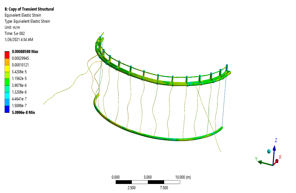
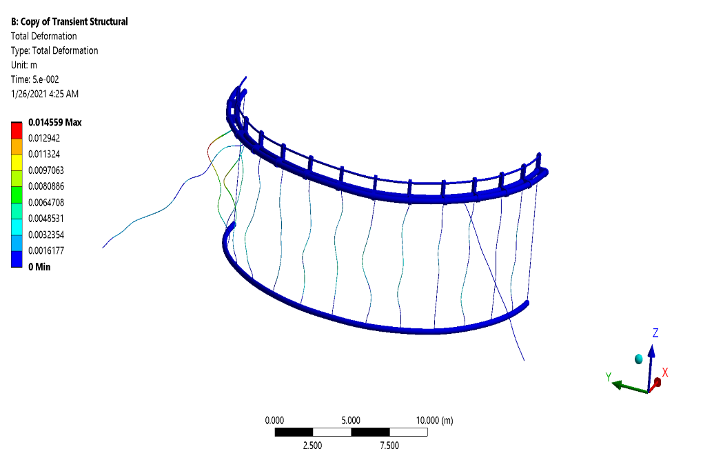
After the solution process, we obtain the results in both Fluent and Transient Structural software. All results are related to the simulation’s final second (0.05 s). In transient structural software, we obtain deformation, strain, and stress contours on the body surface of this fish breeding cage.
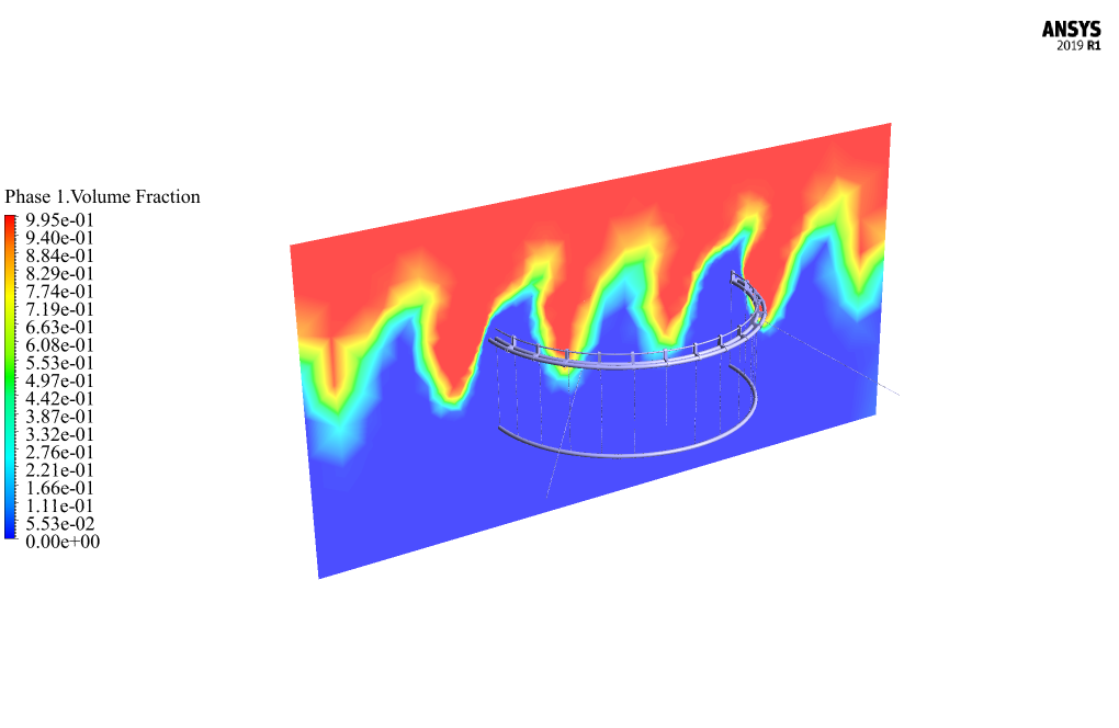
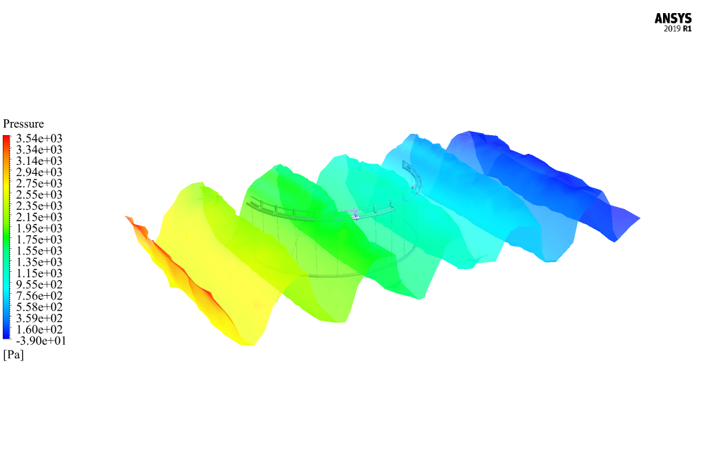
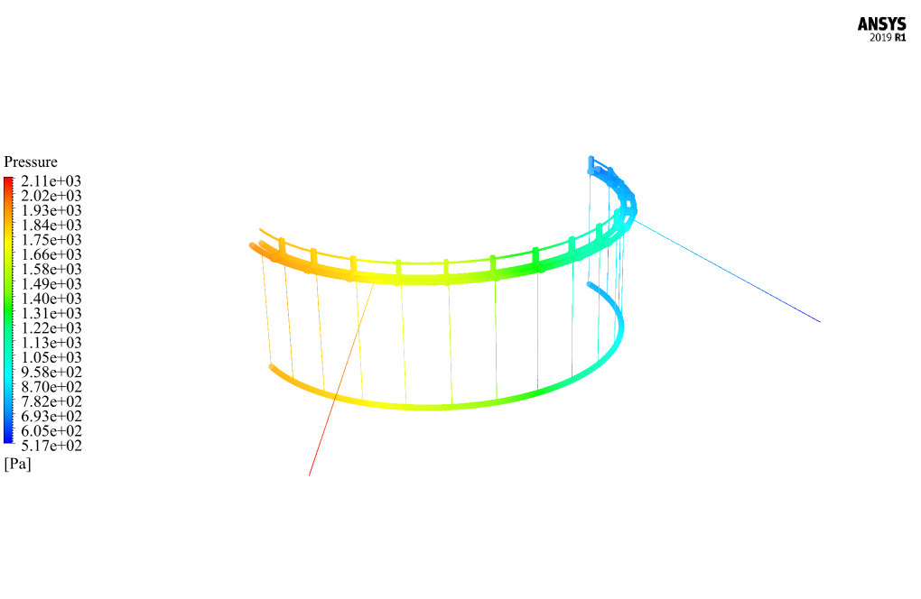
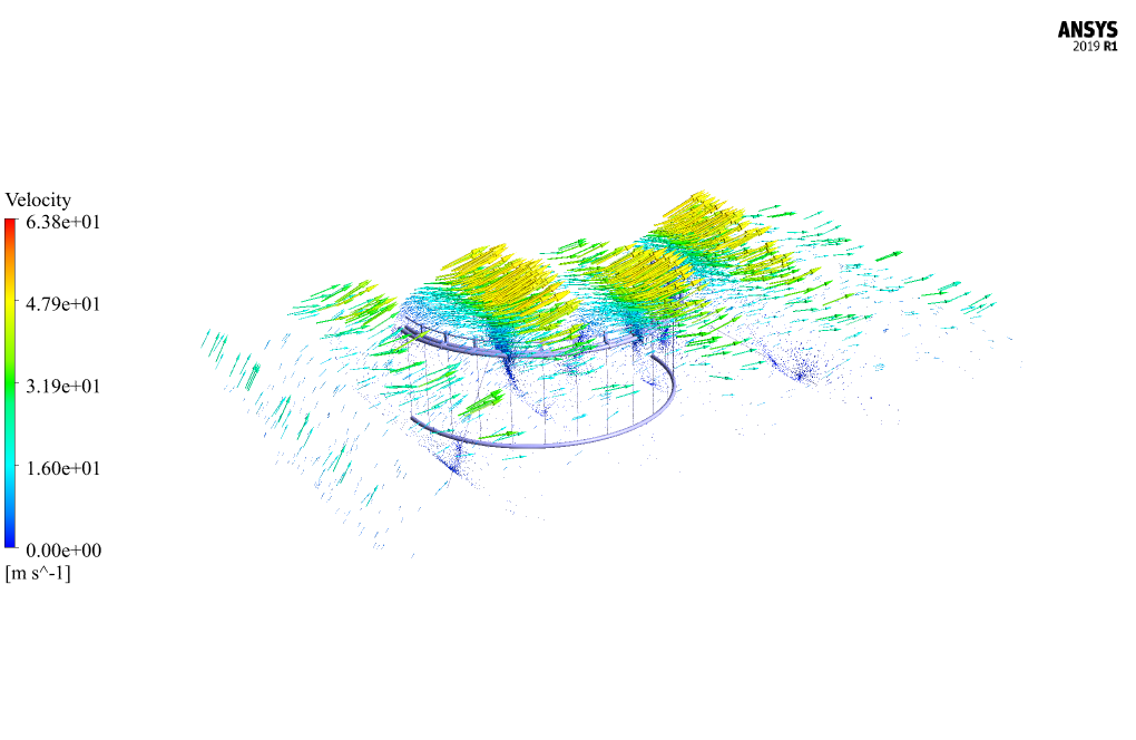
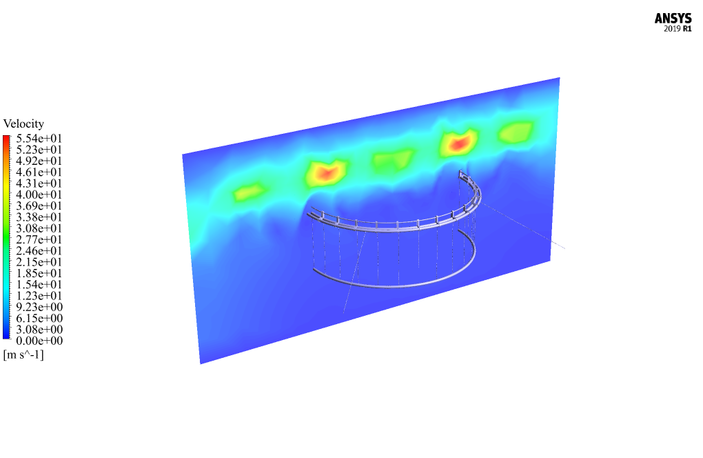
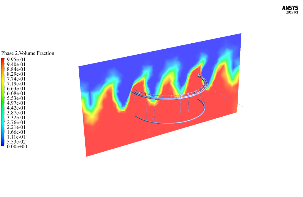
In Fluent software, we obtain two-dimensional velocity, pressure, water, and air volume fraction contours on the middle plate (same as the symmetry plate). Also, we present the contour of the amount of pressure on the surface of the body of this fish breeding cage.
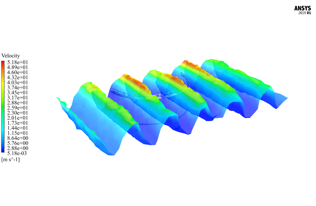
In addition, it has been tried to obtain the surface of the seawater wave and then represents two-dimensional contours of pressure and velocity and velocity vectors on it.
Also, as can be seen in volume fraction contours, the waves created by open channel wave BC are observable. Moreover, the maximum deformation can be seen in the thin bars connecting the top and bottom holders.



Mrs. Daija Bode –
I see that this simulation uses the Fluid-Structure Interaction (FSI) method. Can you explain why this method was chosen for this simulation?
MR CFD Support –
The FSI method was chosen for this simulation because it allows us to accurately capture the interaction between the floating fish cage (the structure) and the seawater (the fluid). This interaction is critical to understanding the behavior of the floating fish cage in real-world conditions.
Adrianna Keeling –
Can this simulation handle different types of fish cages and seawater conditions?
MR CFD Support –
Yes, this simulation can handle different types of fish cages and seawater conditions. We can modify the simulation to accommodate your specific requirements.
Pedro Windler –
How does the simulation handle the buoyancy of the fish cage?
MR CFD Support –
The buoyancy of the fish cage is handled by the FSI method. The buoyancy force is calculated based on the difference in density between the fish cage and the seawater, and this force is then used to determine the cage’s motion in the water.
Dean Jacobs PhD –
I’m amazed by the complexity of the FSI simulation setup described here. It’s fascinating how the input flow rates and the dynamic boundary conditions such as the Open Channel Wave BC are accommodated to introduce realistic water and air interactions in tandem with the floating fish cage. Excellent integration of the VOF model to manage the multiphase aspects!
MR CFD Support –
Thank you for your kind words and for appreciating the technical aspects of the FSI simulation. We aim to provide detailed and realistic setups to ensure that our simulations can mirror real-life scenarios as closely as possible. It’s wonderful to hear that you are pleased with the intricacy and authenticity of our simulation methodologies. Should you have any inquiries or require further assistance, don’t hesitate to reach out!
Dr. Saige Bednar –
The project on the FSI simulation of a floating fish cage was incredibly detailed and educational. The visualization of deformation and stresses along with the fluid dynamics provided valuable insights into the interactions between structures and sea currents. The use of dynamic mesh for the FSI and inclusion of the VOF model for the multiphase flow made the assessment of the design under realistic sea state conditions possible. The initiative to capture wave effects using Open Channel Wave BC is commendable and adds to the reliability of this simulation study.
MR CFD Support –
Thank you for your positive feedback! We are thrilled to hear you found our FSI simulation of the floating fish cage both detailed and educational. It’s our goal to provide high-quality and realistic simulations, and we’re glad that the efforts to include dynamic mesh, VOF multiphase flow modeling, and wave boundary conditions contributed to a meaningful analysis for you. Your appreciation motivates us to continue delivering reliable and useful CFD simulations. Thank you for choosing MR CFD for your learning and research needs!
Prof. Kelton O’Kon –
The detail and scope of this ANSYS Fluent simulation for the fish cage are remarkable! Implementing FSI to calculate the interactions between the seawater and the cage structure opens up real-world applications for designing more efficient and sturdy fish cages. Kudos to the MR CFD team for a comprehensive study that not only uses a dynamic mesh but also includes the effects of open channel wave boundary conditions, illustrating a practical scenario.
MR CFD Support –
Thank you for your positive feedback on our fish cage floating on seawater simulation! We are glad to hear that you appreciate the work put into incorporating FSI and dynamic mesh techniques for a real-life application. Your acknowledgment motivates us to continue delivering high-quality CFD research and analysis. Thank you for choosing MR CFD for your research needs.
Meaghan Cronin –
I enjoyed learning from the ‘Fish Cage Floating on Seawater CFD Simulation by FSI Method, ANSYS Fluent’ product. It was fascinating to see the interaction between the solid structure of the fish cage and the surrounding fluid flows visualized and analyzed using FSI. Understanding the dynamic meshing techniques and system coupling was particularly insightful for applying real-world engineering problems. The graphical representations of deformation, strain, stress contours, and volume fraction contours provided a clear and in-depth comprehension of the fish cage’s behavior in its marine environment. Thanks for the high-quality and informative content!
MR CFD Support –
We’re thrilled to hear that you found the ‘Fish Cage Floating on Seawater CFD Simulation by FSI Method, ANSYS Fluent’ informative and helpful in your learning journey! Understanding the complexities of FSI and dynamic meshing in a real-world application like this can indeed be fascinating, and we are glad that our product met your expectations. We appreciate your positive feedback on the graphical results and how they aided in your understanding of the subject matter. Thank you for taking the time to share your experience!
Arthur Schiller –
I’m highly impressed with how the fish cage floating simulation demonstrates the capabilities of the FSI method for dynamic marine structures. Great job on showcasing the detailed interactions between the fluid and structure!
MR CFD Support –
Thank you for your kind words! We’re delighted to hear you’re impressed with the simulation and the level of detail in demonstrating fluid-structure interactions (FSI) with ANSYS Fluent. Your feedback is very much appreciated!
Dr. Coby Streich –
Fantastic resource! The level of detail in setting up the simulation and explaining the interaction between the fluid and solid components using FSI is appreciated. As someone interested in marine aquaculture and engineering, seeing the marriage of these disciplines through computational simulations is incredibly insightful. It has laid a strong foundation for my own research. The deformation results from the transient analysis were particularly valuable. Kudos to MR CFD for an excellent product!
MR CFD Support –
We are thrilled to hear that you found our ‘Fish Cage Floating on Seawater CFD Simulation by FSI Method, ANSYS Fluent’ so valuable and informative! It’s heartening to see our product contribute to your research in marine aquaculture and engineering. We strive to provide detailed and practical insights into complex simulations and it sounds like we hit the mark for you. Thank you for your wonderful review and we wish you great success in your ongoing work.
Toy Howe –
This CFD simulation teaching tool did an excellent job of detailing the interaction between the fish cage structure and the surrounding seawater. The step-by-step methodology provided a clear understanding of the FSI approach and the use of dynamic mesh. The visualization of deformation and fluid effect on the cage was particularly valuable for grasping the impact of environmental forces on floating structures.
MR CFD Support –
Thank you for your compliments on the CFD simulation course! We’re thrilled to hear that the methodology and visualization aided your understanding of the FSI approach and its implications in environmental analysis of floating structures. Your feedback is much appreciated, and it motivates us to continue creating high-quality learning tools.
Ashton Halvorson V –
I am very impressed by the detailed analysis of the fish cage using the FSI method in ANSYS Fluent. Using half of the symmetric structure to reduce computational cost seems like an efficient technique. The dynamic mesh technique that accounts for the solid-fluid interaction complements the thorough breakdown of the results. This comprehensive study undoubtedly provides valuable insights for fish cage design and its interaction with the marine environment. Great work on implementing the Open Channel Wave BC condition, the results look extremely instructive for understanding wave and cage interactions!
MR CFD Support –
We’re delighted to hear that you appreciate the details and approach of our CFD simulation for the fish cage floating on seawater. It’s rewarding to know that the efforts to reduce computational costs while maintaining high fidelity modeling are recognized. We believe that the dynamic mesh and our handling of the FSI method provide a close representation of the reality. Thank you for acknowledging the use of Open Channel Wave BC conditions. Our goal is to deliver instructive and highly detailed results and it’s great to hear positive feedback from a satisfied customer! Should you have any further questions or need additional information on any aspect, feel free to reach out.
Blanca Murazik –
This simulation study was truly impressive! The detailed approach to utilizing the FSI method for such a practical and complex system as a floating fish cage, exhibits a robust technique in investigating multiple physics interactions in engineering designs. The mesh quality and dynamic mesh adaptation effectively captured the complex movements and interactions between the fluid and solid structures. The adoption of the VOF multiphase model and System Coupling between ANSYS Fluent and Transient Structural to account for two-way interactions was astutely thought out. The successful visualization of strain, stress, and deformation on the fish cage, alongside fluid dynamics characteristics, not only provides the aesthetic contours but essentially the realistic physical behaviors affecting fish farming efficiencies.
MR CFD Support –
Thank you for your thoughtful and comprehensive review! We’re glad to hear that the FSI method applied in the fish cage floating simulation met your expectations and provided you with valuable insights. It’s fantastic to know that the complex interactions captured and visualized through ANSYS Fluent and Transient Structural were effective and intriguing. Your feedback is essential to us, and we take great pride in offering high-quality simulations that can contribute to the practical advancements in engineering. We appreciate your support and look forward to providing you with more innovative simulation solutions.
Alberto Beatty –
After thoroughly studying and applying the Fish Cage Floating on Seawater CFD Simulation by FSI Method, I’ve confidently mastered the skills needed to handle multiphase flow problems and complex FSI analyses in ANSYS Fluent. The simulation runs beautifully, and the level of detail in the results is impeccable, from strain contours to the volume fraction of water and air. The provided learning material has been valuable in my professional development and the ANSYS Workbench environment has become clear. I’ve been able to simulate fluid-structure interactions with precision. Thank you MR CFD Company!
MR CFD Support –
We’re thrilled to hear that our learning product has helped you master such intricate simulations involving Fluid Solid Interactions using ANSYS Fluent. It’s very fulfilling to know that the details and precision we put into our CFD project material are empowering our users and aiding their professional growth. Thank you so much for your positive feedback!
Bettye Dibbert –
I am beyond satisfied with the quality of the fish cage simulation course. The explanation of the FSI method and inclusion of dynamic mesh coupled within the ANSYS Workbench was highly instructive. The challenges of working with ocean wave simulation and body deformation through forces and application of VOF were particularly engaging.
MR CFD Support –
Thank you for your positive feedback! We are thrilled to hear that you found the course on the fish cage simulation informative and engaging. Understanding fluid-solid interactions, especially in complex environments like ocean waves, can be quite challenging. We’re glad our detailed approach utilizing dynamic meshes and VOF multiphase flow model has met your satisfaction. Your success serves as a testament to our commitment to provide comprehensive learning material. If you have any further insight or need assistance in the future, please feel free to reach out to us.
Kris Larson –
I’m really impressed with the comprehensive details provided for the FSI analysis of the fish cage. The explanation of how two-way interaction was accomplished and how deformation and fluid forces were captured is enlightening.
MR CFD Support –
Thank you for your positive feedback! We’re thrilled to hear that our product provided you with a clear understanding of the FSI analysis process using ANSYS Fluent. Our aim is always to deliver comprehensive and educational material. If you have any more questions or need further clarification, feel free to reach out.
Mrs. Sophie Wyman –
How are the boundary conditions set up in this simulation?
MR CFD Support –
The boundary conditions in this simulation are set up to replicate a real-world scenario. The seawater is set to a specific velocity and turbulence intensity, while the fish cage is set to a specific buoyancy and structural properties.