Finned Tube Heat Exchanger CFD Simulation, ANSYS Fluent Training
$80.00 Student Discount
- The problem numerically simulates heat transfer inside a Finned Tube heat exchanger using ANSYS Fluent software.
- We design the 3-D model with the Design Modeler software.
- We Mesh the model with ANSYS Meshing software, and the element number equals 890710.
- The Energy Equation is activated to consider heat transfer.
To Order Your Project or benefit from a CFD consultation, contact our experts via email ([email protected]), online support tab, or WhatsApp at +44 7443 197273.
There are some Free Products to check our service quality.
If you want the training video in another language instead of English, ask it via [email protected] after you buy the product.
Description
Description
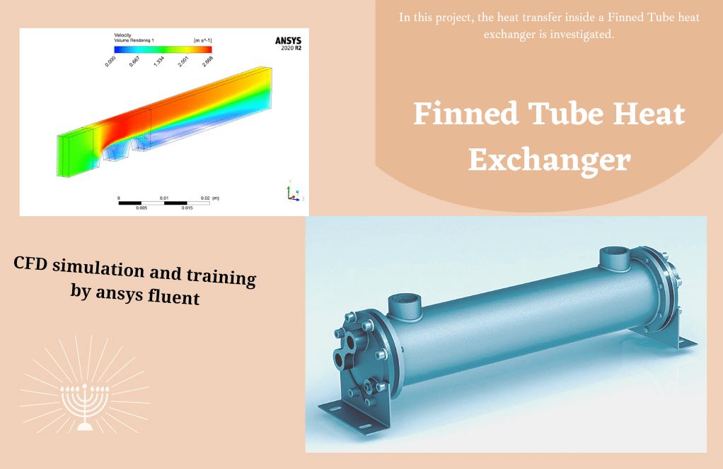
In this project, the heat transfer inside a Finned Tube heat exchanger is investigated by ANSYS Fluent software.
The geometry of this project is designed in the ANSYS design modeler and meshed in ANSYS meshing software. The mesh type used for this geometry is hybrid (structured in the upstream and downstream and unstructured in the main part). The element number is 890710.
It should be mentioned that this geometry only consists of a heat exchanger segment. Since a heat exchanger usually has symmetry, this feature has been used, and instead of solving the flow in the whole heat exchanger, this analysis has been done only in a part of the heat exchanger.
finned tube heat exchanger Methodology
Finned Tube heat exchangers are finned tubes whose main purpose is to create a wider surface about 20 to 30 times larger than the surface of a normal tube heat exchanger. As a result, the volume of the heat exchanger, as well as the economic and process efficiency, are greatly increased.
The energy equation is activated to obtain temperature distribution inside the computational domain.
Since in this analysis, the movement of fluid on the surfaces of the heat exchanger is very important, the SST k-omega model is exploited to solve turbulent flow equations, and the ideal gas model has been used to determine the density changes in proportion to temperature.
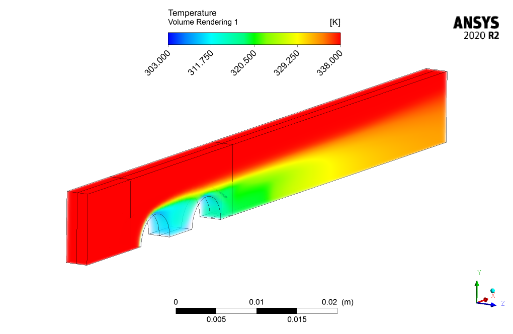
The fluid flow enters the domain with a velocity of 1.42 m/s and a temperature of 338K. This hot flow then collides with the two cold tubes with a temperature of 303K placed in the middle of the domain and loses their temperature.
finned tube heat exchanger Conclusion
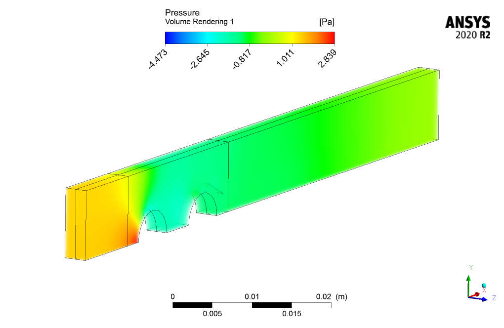
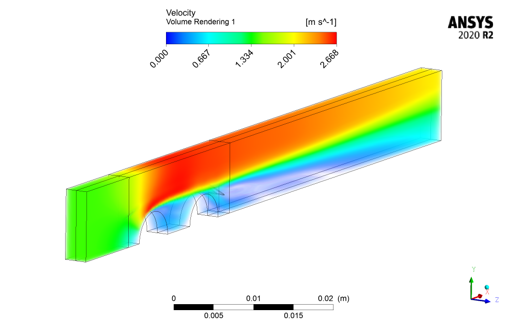
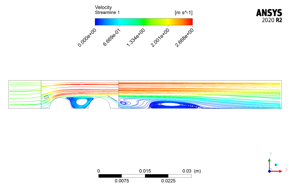
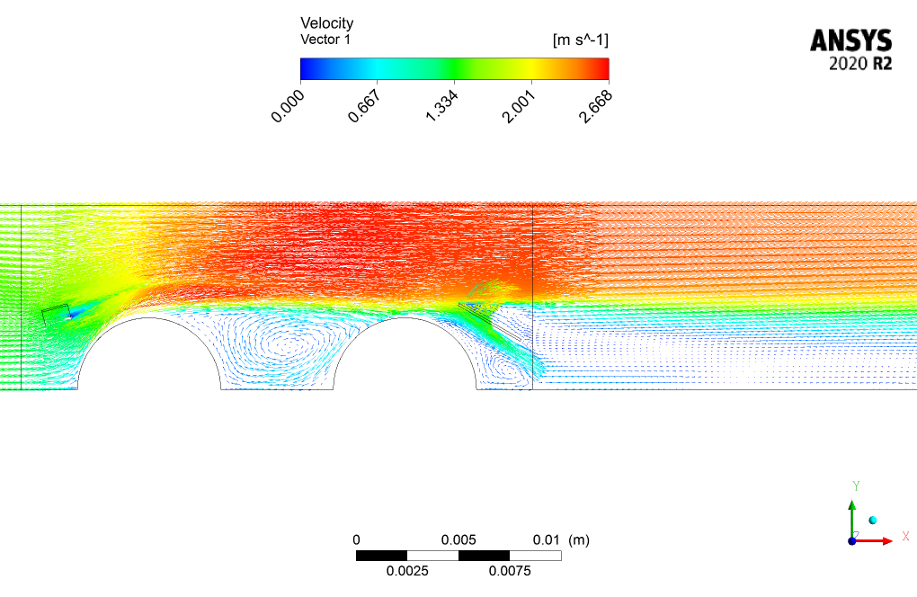
Finally, the contours related to pressure, velocity, temperature, streamlines, and velocity vectors are obtained. As seen in the temperature contour, the fluid flow’s temperature drops near the cold tubes due to the convective heat transfer.
Also, another important point that should be considered is the disadvantages of wake regions that occur between and after the cold tubes, which hampers the heat transfer between the flow and the cold tubes.

Fanny Stamm –
This training on the Finned Tube Heat Exchanger simulation was great! The content was clear and practical, and helped me truly understand the heat transfer dynamics involved. The detail on the use of SST k-omega model and meshing strategy was especially beneficial for my study.
MR CFD Support –
Thank you for your positive feedback! We’re thrilled to hear that our training material on the Finned Tube Heat Exchanger simulation using ANSYS Fluent was clear and insightful. If you have any further questions or need more assistance, feel free to reach out.
Dr. Chyna Gottlieb –
I appreciate the level of detail given for this finned tube heat exchanger CFD simulation on ANSYS Fluent. It’s evident that they are maximizing the operational and economic efficiency. The results seem to be a realistic depiction of how the heat transfer would function in this system.
MR CFD Support –
Thank you for taking the time to write a review of our Finned Tube Heat Exchanger CFD Simulation training. We’re thrilled to hear the details were able to give you a clear and realistic understanding of heat exchanger systems. We continually strive to offer educational materials that are not only informative but practical for real-world applications. Your feedback is greatly appreciated!
Morris Bauch –
I’m really interested to know how the actual heat transfer performance in real-world operations compares to the simulation results. Could the tutorial contain such comparisons, or suggestions on validating the simulation with empirical data?
MR CFD Support –
In our training materials, we provide insights into the expected simulation results and possible comparison with theoretical or empirical data. However, real-world operations can often introduce factors that are not accounted for in simulations. Users looking for validation against empirical data are generally advised to consider setting up experimental validations and using those results to fine-tune their simulation parameters. Unfortunately, our training course does not include real-world operation data, but we encourage users to perform their own validation studies where possible for accurate comparisons.
Gerard Glover –
Very impressive stuff! The detailed analysis of the fin tubes really shows the strength of ANSYS Fluent in simulating complex heat exchanger systems.
MR CFD Support –
Thank you for your kind words! We are thrilled to hear that you’re impressed with the CFD simulation of the Finned Tube heat exchanger using ANSYS Fluent. It is great to know our training materials are serving their purpose and providing detailed insights. We appreciate you taking the time to share your positive experience!
Colt Hamill –
I’m very impressed with how effectively the finned tube design increases the surface area for heat transfer. Was there significant pressure drop observed across the heat exchanger in the simulation?
MR CFD Support –
Thank you for your positive feedback on our Finned Tube Heat Exchanger training! Regarding your question, the simulation you conducted does include results on pressure drops across the heat exchanger. Typically, finned tube designs can lead to additional resistance and thereby a certain amount of pressure drop. Although it’s not stated explicitly within the provided description, the contours of pressure obtained in the study should give insights into the pressure variations, including potential pressure drops. It is an essential aspect commonly analyzed to ensure efficient operation in real-life applications.
Cassie Reilly PhD –
I’m impressed by the level of detail in characterizing the heat exchanger performance. Can you provide more information on how the disadvantages of the wake regions are mitigated in this simulation?
MR CFD Support –
Thank you for your kind words! The disadvantages of wake regions are a complex issue associated with fluid dynamics and heat transfer. While the CFD simulation you mentioned provides visual representations of the wake regions, specific strategies to mitigate their impact often include geometric optimization, altering flow patterns, or employing flow control devices. These strategies are typically established in the design phase and potentially validated through simulation techniques. If you need detailed insights, an advanced study with a focus on wake region management utilizing CFD could help in developing a clear understanding and tailored solutions.
Ayla Barton –
I am very pleased with how comprehensive the simulation steps of the Finned Tube heat exchanger were presented. The increased economic and process efficiency highlighted in the training is noteworthy.
MR CFD Support –
We are thrilled to hear that our Finned Tube Heat Exchanger simulation training met your expectations. Thank you for recognizing the effort we put into presenting a comprehensive guide, and it’s wonderful to know that the benefits regarding efficiency made a positive impression. Your satisfaction is our priority, and your feedback motivates us to keep delivering high-quality training. Don’t hesitate to reach out if you need any further assistance!
Natalie Goyette –
I am highly impressed with the level of details in the simulation for the Finned Tube Heat Exchanger CFD conducted using ANSYS Fluent. The use of hybrid meshing and the explotation of the SST k-omega model for solving the turbulent flow equations certainly contribute to the accuracy of your results. The temperature contour visualization sounds fascinating and clearly demonstrates effective convective heat transfer around the cold tubes. It’s impressive to see how the fluid flow cools as it interacts with the tubes. Great job on this training product!
MR CFD Support –
We’re pleased to hear that you appreciate the attention to detail and found the training material beneficial! Understanding the complex dynamics of a finned tube heat exchanger is essential for efficient design, and our goal is to provide a comprehensive understanding with practical simulations. Your feedback is valuable to us, and we thank you for taking the time to review our product. We look forward to continuing to support your learning journey!
Phyllis Weissnat –
I am thrilled with the results I got from this product! The temperature contours were particularly enlightening, and I now have a deeper understanding of how finned tube heat exchangers work. Kudos to the team for creating such an educational simulation!
MR CFD Support –
Thank you for your positive feedback! We’re excited to hear that our simulation has enhanced your understanding of finned tube heat exchangers. If you have any more questions or need further assistance, feel free to reach out. We’re here to help!
Jordan Prosacco I –
I just finished the Finned Tube Heat Exchanger CFD Simulation training with ANSYS Fluent, and the level of detail provided in the analysis was impressive. The course did a fantastic job explaining complex concepts like the role of finned tubes in enhancing heat transfer and promoting efficiency. I was especially fascinated by seeing the practical impact on temperature distribution and fluid flow visualization. Really solid training!
MR CFD Support –
Thank you so much for your positive review! We’re thrilled to hear that you found the Finned Tube Heat Exchanger CFD Simulation training thorough and informative. It’s great to know that our efforts to provide a detailed and comprehensive learning experience are appreciated by our customers. Should you have any questions in the future or need further assistance, please don’t hesitate to reach out to us.
Maximilian Spinka –
The detail and thorough methodology of the finned tube heat exchanger CFD simulation course were spot on. The practical approach to learning coupled with hands-on software sessions significantly enhanced my understanding of the heat exchange process. Excellent resource material!
MR CFD Support –
Thank you for your kind words! We’re thrilled to know the course met your expectations and helped deepen your understanding of finned tube heat exchangers. Your feedback is highly appreciated, and we hope to continue providing valuable learning experiences.
Eryn Ernser II –
I am thrilled with how detailed the Finned Tube Heat Exchanger CFD Simulation is! The visuals in the output are stunning, making it easy to understand the temperature changes and fluid dynamics around the finned tubes. Great job!
MR CFD Support –
Thank you so much for your kind words! We’re glad to hear that the simulation’s detail level and visual output helped enhance your understanding of the heat exchanger’s performance. Your positive feedback truly motivates us to keep providing high-quality learning resources!
Mrs. Gladyce Mayert –
I am delighted with the depth of detail in the Finned Tube Heat Exchanger simulation. The visuals in the results have been particularly helpful in understanding complex heat transfer interactions!
MR CFD Support –
Thank you for your positive feedback! We’re pleased to hear that our simulation details and visuals have enhanced your understanding of heat transfer in finned tube heat exchangers. If you have any further questions or need more clarity, we’re here to help!
Mrs. Kali Auer I –
Wow, this simulation training must be quite comprehensive! I’m very intrigued by the use of hybrid meshing and how it does in capturing the details of the temperature distributions and flow around the fins. This sounds like an excellent resource for understanding complex heat exchanger simulations.
MR CFD Support –
Thank you for the feedback! We’re thrilled to hear that you appreciate the depth of the simulation training. Our goal is to ensure that learners can effectively grasp the complexities of heat exchanger design, and it’s rewarding to know that the hybrid meshing approach was highlighted in this experience. If you have any further queries, feel free to reach out!
Lillian Lemke –
The training was clear and hands-on, allowing me to understand the principles of finned tube heat exchanger design and operation thoroughly. The hybrid meshing technique was particularly interesting to learn about.
MR CFD Support –
We’re glad to hear that you found the finned tube heat exchanger CFD simulation training clear and informative. Thank you for highlighting the effectiveness of learning about hybrid meshing techniques through our ANSYS Fluent training module. We appreciate your positive feedback!
Dr. Pierce Kutch –
The finned tube heat exchanger simulation was extremely insightful! The visuals were clear, and I could grasp complex concepts with more ease. Thanks, MR CFD for such a comprehensive training package!
MR CFD Support –
We’re delighted to hear that you found our Finned Tube Heat Exchanger simulation training so comprehensive and helpful. Your satisfaction with the clarity and detail of the concepts is very important to us. Thank you for choosing our products for your learning experience, and we appreciate your positive feedback!
Luigi Larson –
I am impressed with the level of detail in the simulated results. Could you share what practical applications this type of finned tube heat exchanger simulation might have?
MR CFD Support –
Thank you for the compliment! Finned tube heat exchanger simulations like this one are vital for optimizing thermal systems employed in various industries including HVAC, refrigeration, automotive, and aerospace sectors. They help engineers assess performance under different conditions, enhance designs for better heat transfer efficiency, and reduce energy consumption while maintaining desired temperatures.
Prof. Casimir Wuckert –
I very much like the detailed setup for the simulation of the Finned Tube heat exchanger using ANSYS Fluent. The utilization of SST k-omega model for turbulent flows and addressing the effect of wake regions shows depth in the simulation process. It seems that the computational work for analyzing heat exchangers has been done thoughtfully, which likely contributes to an effective design and operational understanding of these systems.
MR CFD Support –
Thank you! We’re glad to hear you appreciated the details and methodology involved in the Finned Tube heat exchanger simulation. It’s exciting to know that our product contributed to your deeper understanding of such systems. If you have any more feedback or need further assistance, please feel free to reach out.
Mr. Percival Will PhD –
How does this project take into account the heat loss to the environment?
MR CFD Support –
In this project, the focus is on the convective heat transfer between the finned tube and the fluid flowing through the heat exchanger. Heat loss to the environment can be modeled by applying appropriate thermal boundary conditions at the external surfaces of the exchanger. These conditions could be a fixed temperature, a heat flux (which could be set to zero for adiabatic walls), or convective boundary conditions that calculate heat loss based on the difference between the external wall temperature and the ambient temperature.
Jolie Ritchie IV –
This project really enhanced my understanding of heat exchangers. I was impressed by the detailed analysis and the clarity in the results, as seeing the temperature contour and wake regions helped solidify the concepts. Great learning experience!
MR CFD Support –
Thank you so much for your kind words! We’re delighted to hear that our simulation provided you with clear insights and helped enhance your understanding. We strive to produce informative and helpful tutorials, and it’s great to know when they make a difference. If you have any more questions or need further clarifications, please don’t hesitate to ask!
Prof. Christa Ryan I –
I’ve always been fascinated by the efficiency enhancements gained through finned designs. Could you elaborate on what exactly helps finned tube exchangers achieve better heat transfer compared to normal tube heat exchangers?
MR CFD Support –
Finned tube heat exchangers increase heat transfer efficiency primarily due to their larger surface area. This increase in surface area enhances the rate of heat exchange between the fluid and the tubes, allowing for better thermal performance and more effective heat transfer. Furthermore, the design of finned tubes promotes turbulent fluid flow which also contributes to an increased rate of convective heat transfer.
Dr. Mya Wilderman I –
This Finned Tube heat exchanger simulation training was just what I needed to understand the complex thermal interactions. The detailed methodology and clear explanation of the turbulence model selection helped me grasp the fundamentals quickly. The hybrid mesh structure enhanced my understanding of meshing techniques for diverse geometrical complexities. The results presentation, especially the contours really showed the effectiveness of the heat exchanger design and helped me solidify my learning on fluid and thermal analyses. Great work on this comprehensive training experience!
MR CFD Support –
Thank you for your kind words! We are thrilled to hear our training on Finned Tube heat exchanger simulation using ANSYS Fluent was helpful for your understanding of thermal interactions and meshing techniques. We always strive to provide clear and detailed explanations, and it’s rewarding to know the methodology and results presentations were effective and informative. If you have any further questions or need additional support in your learning, feel free to reach out. Thank you again for choosing MR CFD Company’s learning products!
Edmund Jaskolski –
This training has truly elevated my understanding of heat exchangers. The step-by-step methodology clarified complex concepts, and the result visualizations were crisp, showcasing the efficiency of finned tubes. It’s especially impressive how SST k-omega modeling and the treatment of wake regions enhance the learning experience. I’m eager to apply these insights in practical scenarios. Excellent work setting up the simulations to provide a comprehensive learning tool.
MR CFD Support –
Thank you for the wonderful feedback! We’re thrilled to hear that our Finned Tube Heat Exchanger CFD simulation course has provided valuable insights for you. Understanding the impact of different geometries and flow characteristics on heat transfer is vital, and we’re delighted our course could help clarify these complexities. If you ever have any questions or need further assistance in applying the concepts, our team is here to support you. Good luck with your practical applications!
Antonette Nienow MD –
This project is excellent! The detailed breakdown of the finned tube heat exchanger and the simulation approach was very insightful. The results demonstrating the temperature drop and the flow dynamics make this training product incredibly valuable. Well done!
MR CFD Support –
Thank you for your positive feedback! We are truly glad to hear that you found our training material on finned tube heat exchanger simulation in ANSYS Fluent helpful and insightful. It’s great to know that the detailed explanation and results met your expectations. If you ever have more questions or need further clarifications in the future, please don’t hesitate to reach out.