Flap Effect on Trailing Edge of an Airfoil Simulation, ANSYS Fluent Training
Free
- The problem numerically simulates the Flap Effect on the Trailing Edge of an Airfoil using ANSYS Fluent software.
- We design the 2-D model by the Design Modeler software.
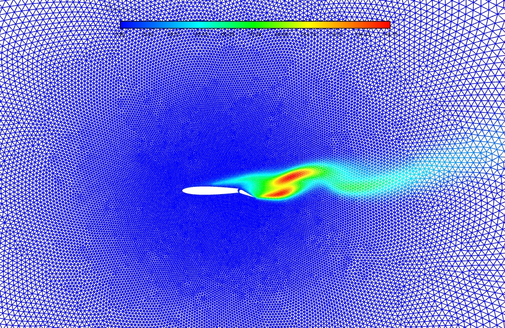
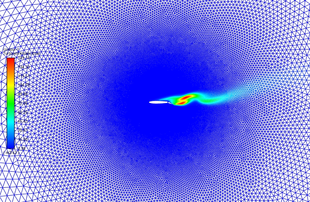
- We mesh the model with ANSYS Meshing software, and the element number equals 64731.
- We aim to study Drag and Lift forces in this project.
To Order Your Project or benefit from a CFD consultation, contact our experts via email ([email protected]), online support tab, or WhatsApp at +44 7443 197273.
There are some Free Products to check our service quality.
If you want the training video in another language instead of English, ask it via [email protected] after you buy the product.
Description
Description
In this project, steady airflow over a flapped airfoil with an attack angle equal to 12 degrees is investigated by ANSYS Fluent software. We perform this CFD project and investigate it by CFD analysis.
The present model is designed in two dimensions using Design Modeler software. The meshing of the model has been done using ANSYS Meshing software. The element number is 64731.
Flap Methodology
A flap is a high-lift device used to reduce the stalling speed of an aircraft wing. Flaps are usually mounted on the wing trailing edges of a fixed-wing aircraft. Flaps also cause an increase in drag, so they are retracted when not needed.
This project investigates steady airflow over a flapped airfoil with an attack angle of 12 degrees. The air enters the domain with a velocity magnitude of 45m/s and passes over the airfoil.
To capture the flow patterns near the airfoil’s surface and to calculate drag and lift forces precisely, the SST k-omega model is used.
Flap Conclusion
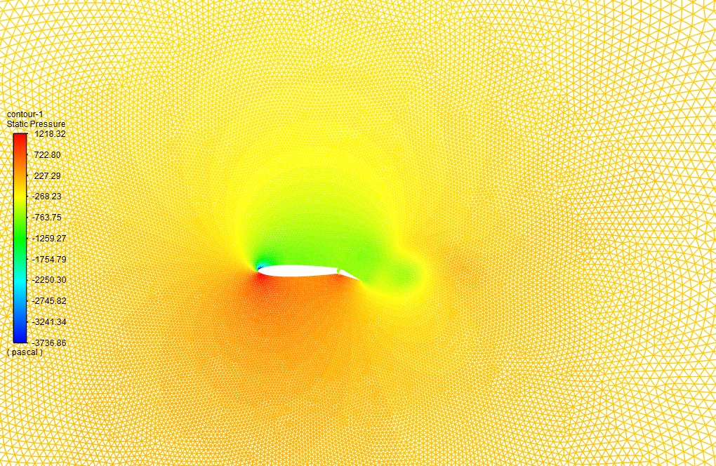
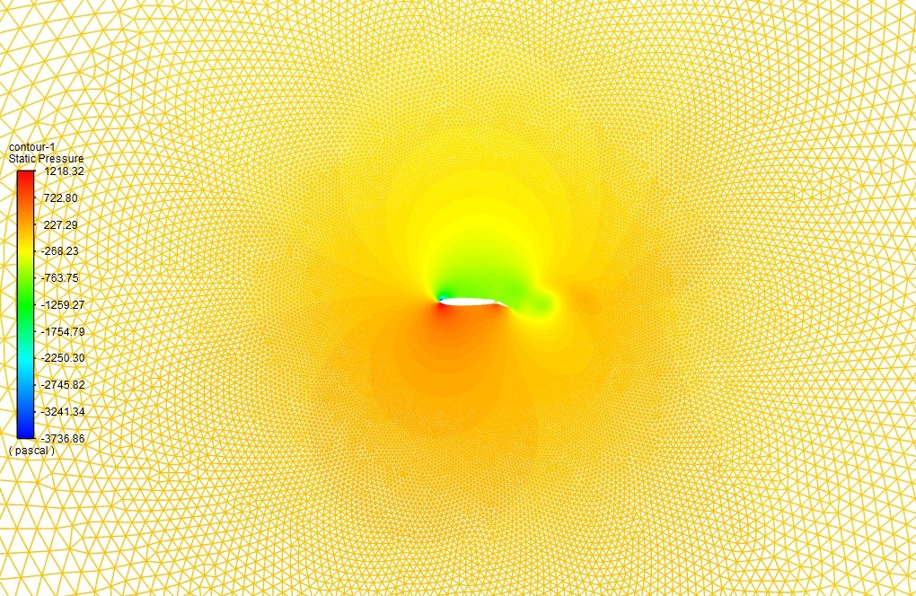
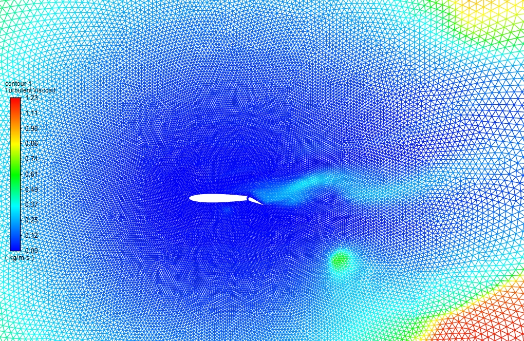
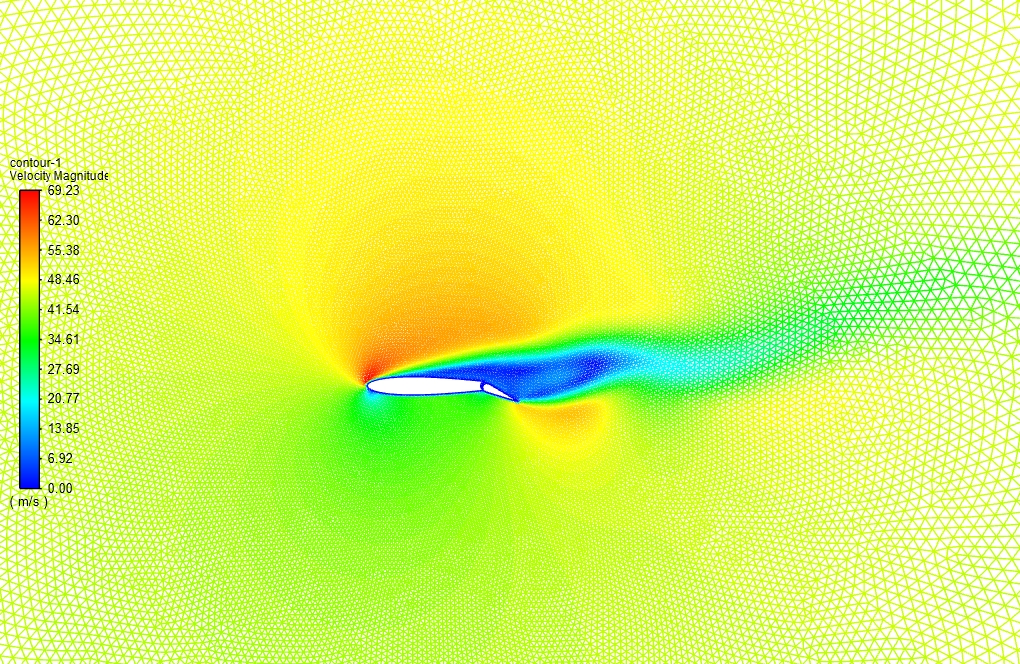
At the end of the solution process, two-dimensional contours related to the velocity, pressure, and turbulent viscosity inside the domain are obtained. The contours related to pressure clearly show how the pressure difference between the pressure and suction sides of the airfoil can contribute to the generation of lift force.
Also, the stagnation point in the leading edge can be observed. Furthermore, the wake region is conspicuously observable in the velocity and turbulent viscosity contour.
In addition, based on the calculated values for lift and drag forces, The lift coefficient of an airfoil with and without the flap is equal to 1.2182 and 1.0530, which shows the effectiveness of the flap in aerodynamic lift force generation.
Moreover, the drag coefficient of the airfoil in the presence of a flap is equal to -0.0273, which is less than airfoil without a flap, where the drag coefficient is equal to -0.0822, which proves that flap presence is effective in drag force reduction that is favorable in aerodynamics applications.

Dr. Alverta Block DVM –
Can the simulation predict the lift and drag forces on the airfoil?
MR CFD Support –
Yes, the simulation provides detailed information about the pressure and velocity distribution around the airfoil, which can be used to calculate the lift and drag forces.
Judd Batz –
I’m truly fascinated by the aerodynamic simulation results! Could you shed light on why the drag coefficient is negative when a flap is deployed on an airfoil?
MR CFD Support –
Thank you for your kind words. The negative value for the drag coefficient seems unusual and could be an error in reporting or interpreting the results. Typically, drag coefficients are positive since drag is a resistive force. The negative sign may refer to the relative decrease in drag compared to the airfoil without a flap, emphasizing the pressure reduction due to the flap’s presence. However, without examining the specifics of the simulation settings, it’s hard to provide a definitive answer.
Tiara Ratke –
How does the simulation model the interaction between the airfoil and the surrounding air?
MR CFD Support –
The simulation uses the Navier-Stokes equations to model the fluid dynamics around the airfoil. The turbulence is captured using the k-epsilon model, which accurately predicts the flow separation and reattachment around the flap.
Alfred Kirlin –
Wonderfully detailed product! Does this simulation also allow for an analysis of how different flap angles affect the lift and drag on the airfoil?
MR CFD Support –
Yes, with the versatile tools available in ANSYS Fluent, users can modify the flap angles to study their effects on lift and drag. Adjusting the angle and analyzing the impact on the airflow can enhance understanding of aerodynamic principles and help in optimizing wing designs for various flying conditions.
Kyle Braun –
The SST k-omega model was a great choice for capturing flow patterns! Really impressive results with the lift and drag coefficients.
MR CFD Support –
Thank you for your kind words! We’re thrilled that you recognized the effectiveness of the SST k-omega model in our simulation. It’s wonderful to hear that you found the results regarding the lift and drag coefficients impressive and beneficial for aerodynamic applications!
Modesta Roob V –
After mastering this training, will I be able to adjust the flap settings on different airfoils and at different angles to analyze their effects on lift and drag?
MR CFD Support –
Absolutely, the purpose of this training is to familiarize you with the simulation of aerodynamic elements like flaps using ANSYS Fluent. With the knowledge acquired, you’ll be able to conduct similar analyses on various airfoil designs and configurations, tailoring flap angles, and other parameters to study their influence on aerodynamic forces.
Makenzie Roob V –
This training enhanced my understanding of airflow over flapped airfoils considerably. The visual representations of velocity and pressure differences were clear and edifying, demonstrating the intrinsic effects of flaps on aerodynamics.
MR CFD Support –
Thank you for your positive feedback! We are delighted to know that our simulation for flap effect on the trailing edge of an airfoil was informative and helped in enhancing your understanding of aerodynamics. We strive to deliver clear visual demonstrations and are glad that you found the data representations effective.
Armando Kovacek –
Can the simulation model the effects of different flap angles on the airfoil’s performance?
MR CFD Support –
Yes, the flap angle in the simulation can be easily adjusted to study its effects on the lift and drag forces, as well as the stall behavior of the airfoil.
Mr. Tyler Mayer I –
I recently utilized the ‘Flap Effect on Trailing Edge of an Airfoil’ simulation product by MR CFD for a project. The detailed solution offered two-dimensional contours that captured important differences with and without the presence of the flap. I was particularly pleased with the enhanced lift coefficient when the flap was deployed, which clearly demonstrated its functionality. Moreover, seeing the drag force decrease with the flap’s inclusion simplified the principles of aerodynamics for practical aviation applications. Notably remarkable was understanding the wake region through the velocity and turbulence visualizations. Exceptional work on creating a powerful learning tool!
MR CFD Support –
Thank you for sharing your positive experience with our ‘Flap Effect on Trailing Edge of an Airfoil’ CFD simulation training product. We’re thrilled to hear that our simulations have provided you with clear, practical insights into the aerodynamics of airflow over a flapped airfoil. Insightful feedback like yours inspires us to continue delivering high-quality educational resources. If there’s anything else you’d like to explore or any further assistance you might need, please let us know!
Alphonso Schultz –
It’s truly impressive how flaps can increase lift without significantly increasing drag, as shown in this thorough simulation. The visualization of the pressure difference and wake region is particularly helpful for understanding the aerodynamics involved.
MR CFD Support –
Thank you for your positive feedback! We’re thrilled to know that you found the simulation’s visualization and explanation helpful in understanding the complex aerodynamics of a flapped airfoil. Your appreciation motivates us to continue providing detailed and quality CFD training materials.
Grady Jones I –
This training material opened up new perspectives in aerodynamics for my projects. The flap influence on the trailing edge was particularly enlightening and directly applicable. Great job on providing practical insights along with solid theory.
MR CFD Support –
Thank you for the positive feedback! We’re delighted to hear that our training material is not only informative but also applicable to your projects. Your appreciation is highly motivating for our team. If you need further assistance or have more questions, feel free to reach out. We look forward to continuing to support your endeavours in aerodynamics.
Ms. Marisa Hammes –
I was truly impressed by the detailed analysis of the flap effect on the airfoil provided by the ANSYS Fluent Training. As an aerospace enthusiast, I am thrilled with how well the simulation captured complex flow phenomena and realistically reflected the aerodynamic forces involved. Kudos to MR CFD for such an informative experience that clearly explains the physics in action!
MR CFD Support –
Thank you for your kind words! We are incredibly pleased to hear that our ANSYS Fluent Training on the effect of the flap on the trailing edge of an airfoil has been both informative and thrilling for you. It is always our goal to create comprehensive and realistic simulations that can aid in understanding complex physics. Your appreciation really encourages us to continue delivering high-quality learning products.
Uriel Kassulke –
Fantastic training simulation! Visualizing the effects of the flap on the airfoil through these results was both insightful and impressively clear. It gave me a solid understanding of the dynamics involved.
MR CFD Support –
We’re thrilled to hear that our simulation provided you with a clear and comprehensive understanding of flap effects on airfoil aerodynamics. Thank you for your positive feedback!
Brendon Hayes PhD –
Extremely satisfied with MR CFD’s ‘Flap Effect on Trailing Edge of an Airfoil’ training. The detailed explanation of flaps’ impact on aerodynamic properties using ANSYS Fluent was insightful. The results truly highlight the significance of flaps in managing lift and drag, reflecting the trainers’ expertise.
MR CFD Support –
Thank you for your positive feedback! We are delighted to hear that our training was informative and made a significant impact on your understanding of aerodynamics in the context of airfoils and flaps. If you have more inquiries or need further assistance, don’t hesitate to reach out. Your satisfaction is our top priority!
Curtis Nitzsche –
The description is enlightening! I loved seeing how the flap’s presence impacts both lift and drag. Real game-changer for aerodynamic efficiency!
MR CFD Support –
Thank you for your positive feedback! We’re thrilled to hear that you found the simulation outcomes about the flap’s influence on lift and drag to be informative. It’s always our goal to provide insightful and practical CFD analysis. If you have any further insights or questions, feel free to share!