Radiator Thermal Performance with Fans, Validation
$400.00 Student Discount
- The problem numerically simulates Radiator Thermal Performance with Fans using ANSYS Fluent software.
- We design the 3-D model with the Design Modeler software.
- We Mesh the model with ANSYS Meshing software, and the element number equals 4683472.
- This project is simulated and validated with a reference article.
- We use the Fan boundary condition and define a Pressure Jump.
- We use a UDF to define the temperature profile.
To Order Your Project or benefit from a CFD consultation, contact our experts via email ([email protected]), online support tab, or WhatsApp at +44 7443 197273.
There are some Free Products to check our service quality.
If you want the training video in another language instead of English, ask it via [email protected] after you buy the product.
Description
Radiator Thermal Performance with Fans, Paper Numerical Validation, ANSYS Fluent Tutorial
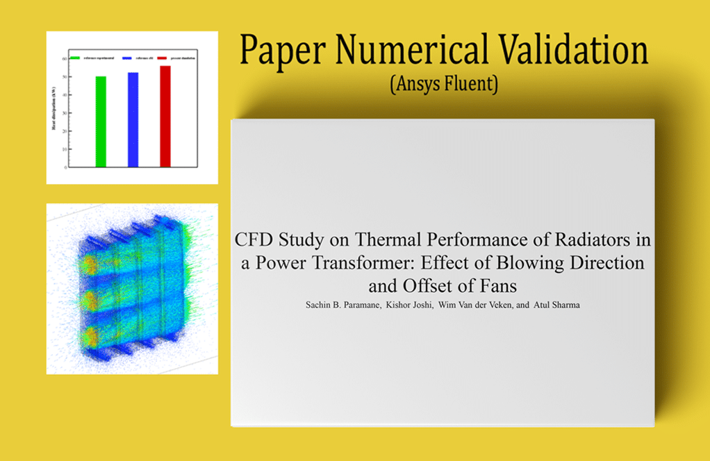
The present problem concerns heat transfer and airflow simulation around a radiator. The present simulation is based on the reference article “CFD Study on Thermal Performance of Radiators in a Power Transformer: Effect of Blowing Direction and Offset of Fans” using ANSYS Fluent software.
Also, the current CFD simulation results are compared and validated with the results of the reference paper. This radiator has three fans for transmitting airflow in the horizontal direction. This radiator consists of several rows of fins and aluminum plates that increase the heat transfer rate.
The present modeling has been done in three dimensions using Design Modeler software. The model consists of three main parts: the radiator body, fans, and the surrounding space.
The radiator consists of four sections, each consisting of fourteen rows of plate fins and two hot water transfer pipes at the top and bottom of the radiators.
Also, three fans have been used to create airflow next to the body of the radiators; The location of the fans in the model of horizontal radiators is on the left side of the radiator and creates airflow in the horizontal direction.
The meshing of the present model has been done using ANSYS Meshing software, and the mesh type is unstructured. Also, according to the physics of the problem and the need for heat transfer between the radiator fins and the airflow, the INFLATION boundary layer mesh is used on the surfaces of the radiator walls.
Also, the FACE SIZING command on the wall surfaces of the radiator fins is used to increase the mesh accuracy. The element number is equal to 4683472.
Radiator Methodology
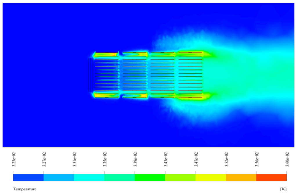
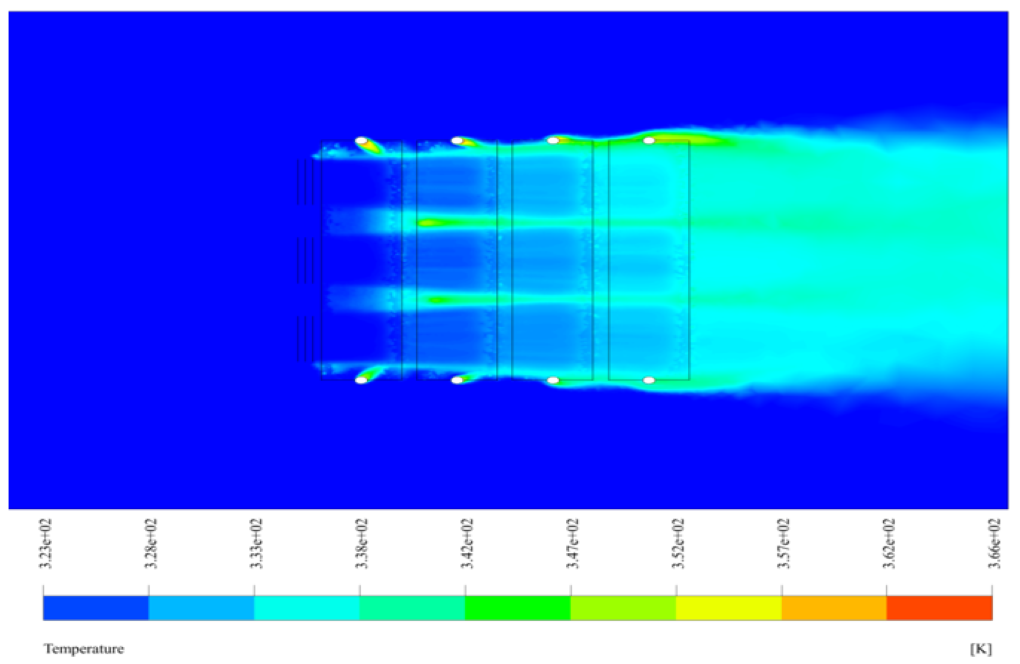
Hot water flows through the upper and lower pipes of the radiator and its middle fins; In fact, it is assumed that all the walls of the pipes and radiator fins have determined temperatures at different points.
Therefore, the temperature profile depends on the height of the radiator plates. The TEMPERATURE boundary condition applying a UDF is used to define this temperature profile.
This temperature profile of the plates on which the UDF is written is obtained in such a way that the temperature of the hot water entering the radiator from the upper part is initially assumed to be 366.15 K, which after flowing into the pipes and downward moving, heat exchange with the ambient airflow, and reaches its lowest temperature value of 353.15 K in the lower part.
These temperature changes are mainly due to the movement of the flow in the vertical direction. The mentioned UDF is written linearly in the form 346.15 + 5 * y. Also, to apply the effect of the fans, the Fan boundary condition is used in the plates located in the middle of the side of the radiator.
Since the input flow to these fans is in the horizontal direction, the rotational speed around the x-axis is considered. The flow in the fans is assumed to be suction by default, but in this model, the fan flow must be blowing, so Reverse Fan Direction is activated to change the airflow direction in the fan.
Also, the amount of pressure jump for each fan is defined as a polynomial pressure function in terms of velocity; Thus, the polynomial function has two coefficients equal to 80 and -10.
Radiator Conclusion
At the end of the solution process, we calculate the net heat loss rate from the radiator plates to the airflow and compare it with the reference paper for Validation. To make this comparison, we use Figure 5 of the article and the ONAF mode (with forced convection heat transfer). We can assume that the rate of heat loss from the radiator body to the surroundings is equal to the air temperature difference between the inlet and outlet. Thus, by using the Report and selecting the Total Heat Transfer Rate option from the Flux Report section, we can calculate the difference in heat transfer rate between the input and output boundaries.
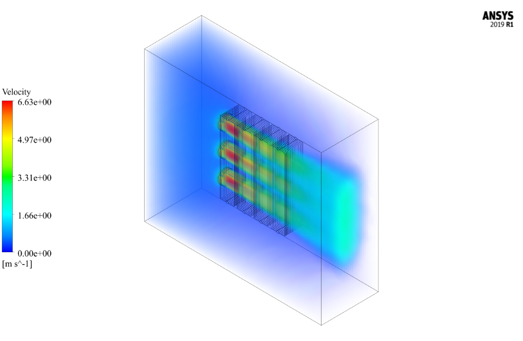
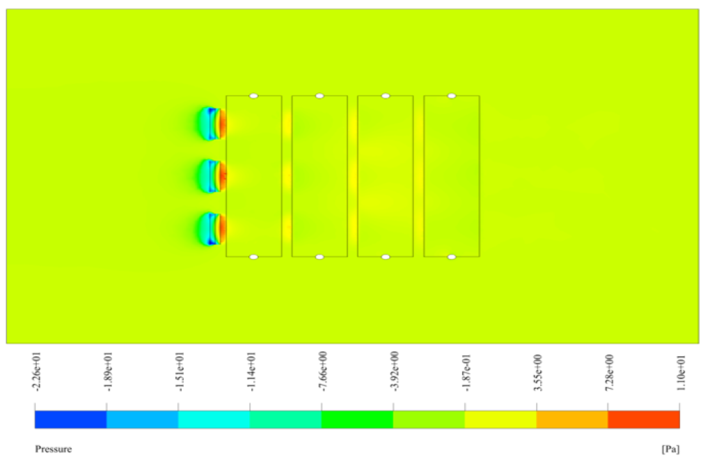
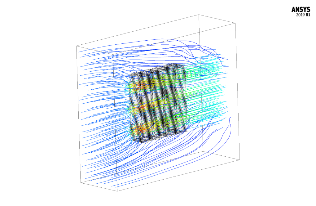
Also, after the completion of the solution process, we obtain two-dimensional and three-dimensional contours of temperature, velocity, and pressure, as well as three-dimensional path lines and velocity vectors.


Samara Miller –
The use of face sizing and inflation layers for increasing mesh accuracy is interesting. Have you found that these specific meshing techniques used in the simulation greatly affect the accuracy of your final heat transfer rate calculations?
MR CFD Support –
Yes, the use of face sizing and inflation layers in meshing greatly enhances the accuracy of heat transfer rate calculations. These techniques refine the mesh near the walls where temperature and velocity gradients are high, capturing the physics of the problem with more precision, which results in more accurate computations of the thermal performance of the radiator.
Pascale Klein –
The tutorial was incredibley detailed and clear. The UDF application for the temperature profile gave me great insight into simulating realistic thermal conditions! Thank you for such a comprehensive learning tool!
MR CFD Support –
Thank you for your kind words! We’re pleased to hear that you found the tutorial on Radiator Thermal Performance with Fans detailed and helpful. It’s great to know the UDF application for the temperature profile was insightful for you. Your feedback is much appreciated, and if you have any more questions or need further assistance, don’t hesitate to reach out!
Ernestine Rogahn –
I was amazed at the accuracy of the simulation compared to empirical data in the reference paper. The detailed setup of boundary conditions and UDF implementation for the temperature profile is impressive!
MR CFD Support –
Thank you for your wonderful feedback! We’re thrilled the numerical validation and detailed approach in setting up the CFD simulation met your expectations and closely matched empirical results. Your commendation encourages us to continue delivering high-quality simulations and tutorials.
Leslie Kirlin –
I was especially impressed by the temperature profile implementation using UDFs in this simulation. Could you explain if this increased relatability to real-world scenarios for the study on transformer radiators?
MR CFD Support –
We appreciate your kind words and interest in the practical aspects of our simulation. Yes, using user-defined functions (UDFs) to implement the temperature profile allowed us to more accurately mimic the gradient in temperature due to heat transfer from the radiator, as would occur in a real-world scenario. This level of detail is crucial for a valid comparison with the thermal data from the reference paper and ensures the simulated behavior of airflow and heat exchange closely matches that in actual power transformer radiators.
Sim Green –
The learning material was really thoroughly presented! Seeing how the tutorial walks through the steps of validating the simulation against the reference paper gave me strong confidence in the approach and methodology. The clear delineation and explanation of boundary conditions and the use of UDF for temperature profiles are particularly impressive.
MR CFD Support –
We truly appreciate your positive feedback on our Radiator Thermal Performance with Fans tutorial. It’s great to hear that you found the demonstration of the validation process and detailed explanations about the boundary conditions and UDF usage both insightful and reassuring. Thank you for taking the time to review our product! If you ever have any more questions or require further assistance with our learning materials, please do not hesitate to reach out.
Rahsaan Littel –
I have noticed increased efficiency in my power transformer since using this tutorial. The simulation closely matched the real results I observed, and this has given me great confidence in using your tutorials for future thermal management projects. Thank you for a detailed and very helpful guide!
MR CFD Support –
We’re thrilled to hear that our ‘Radiator Thermal Performance with Fans’ tutorial has been beneficial for you, especially in increasing the efficiency of your power transformer. It’s always rewarding to learn that our simulations and guidelines can translate into noticeable real-world improvements. We look forward to supporting you in your future thermal management endeavors. Thank you for taking the time to share your positive experience!
Mr. Turner Dare II –
I particularly admired the comprehensive methodology behind simulating the thermal performance of the radiator with fans. Especially the use of the UDF for establishing the temperature gradient and the careful consideration for fan direction to mimic the blowing effect demonstrated remarkable attention to detail. Could you elaborate on how the simulation defines these fans’ properties to maintain accuracy in the computational model?
MR CFD Support –
In the simulation, fan properties are defined to maintain accuracy by using the ‘Fan’ boundary condition and incorporating a polynomial pressure function that incorporates coefficients to represent the pressure jump across the fans. The flow direction is reversed to simulate the blowing action and is aligned with the rotational axis of the fans as per the model’s requirements. The combination of these settings helps achieve accurate representation of the fan behavior within the simulated environment.
Holden Okuneva –
I’m interested in understanding how you compared the net heat loss rate from the radiator with the reference paper. Could you provide more details about this validation process?
MR CFD Support –
In the validation process, we used the net heat loss calculated in our simulation and compared it with the heat loss data derived from Figure 5 of the reference article, which is in ONAF mode (Oil Natural Air Forced requiring forced convection heat transfer). We measured the temperature difference of air between the inlet and outlet and applied it to compute the total heat transfer rate using the flux report section in ANSYS Fluent. By ensuring close agreement with the published data, we validated our numerical methods and simulation results for accuracy and reliability.
Nathaniel Emard –
I am delighted with the results obtained in comparison with the reference paper. What reason can be attributed to any minor differences that might have been observed in the computational results compared to those indicated in the reference text?
MR CFD Support –
Minor differences in computational results in comparison to those in the reference paper may be attributed to several factors such as slight variations in the assumed input parameters, the mesh quality and density, the convergence criteria used in the simulations, and the types of numerical schemes selected for the CFD analysis. Potential discrepancies might also arise from the simplifications and assumptions in the model setup.
Jarod Wintheiser –
I’m really impressed by the level of detail in this simulation study for the radiator thermal performance. The incorporation of real-life conditions and comparison for validation with documented research enhances the credibility of the learning material. Great job MR CFD Company!
MR CFD Support –
Thank you for your positive feedback! We strive for accuracy and detail to provide high-quality simulations that can be trusted and validated, so we’re glad to hear that our efforts resonate with our customers. We appreciate your support!
Dr. Wade Huels V –
The way UDF is applied for temperature profiling seems very interesting—any chance you can explain a bit more about how exactly this UDF interacts with the model and influences the simulation results?
MR CFD Support –
Certainly! The UDF (User-Defined Function) defines a temperature profile across the radiator fins that reflects the decrease in water temperature as it moves from the top (where it’s hotter) to the bottom (where it’s cooler)—this is reflected in the UDF as 346.15 + 5 * y. When applied to the simulation, the UDF causes temperature gradation, which influences the heat transfer from the water to the fins and subsequently to the air. The airflow from the fans aids in removing this heat, contributing to the radiator’s overall thermal performance. Essentially, the UDF is crucial for modelling the temperature-dependent heat transfer across the radiator’s surface accurately.
Prof. Jacey Towne –
I’m pleased with how the simulation matched the study in the reference paper! It augmented my understanding of thermal flows. Could you specify the range of fans’ pressure polynomial coefficients you mentioned?
MR CFD Support –
Thank you for your kind words! The pressure polynomial coefficients used for modeling the fans are ’80’ for the constant term and ‘-10’ for the linear term with respect to velocity. These were determined based on the fan characteristics necessary for the simulation to match the referenced study’s conditions.
Eloy Renner –
This tutorial for the radiator simulation seems thorough, but could you tell me if the polynomial function used for the pressure jump is common in such studies, or was it specifically derived for this case?
MR CFD Support –
In CFD simulations, polynomial functions like the one used for describing the pressure jump across the fans are not uncommon and are used when a specific functional relationship is known or assumed between the variables involved. In this particular study, it was chosen based on empirical data or theoretical understanding described in the reference paper. In general, creating a function to model the pressure drop is very much case-dependent and is usually based on experimental data, fundamental fluid dynamics, or specified performance curves of specific equipment being modeled.
Susan Denesik –
Wow, the comparative analysis and the inclusion of validation using a reference paper add a lot of credibility to the study. It’s impressive how the boundary conditions mimic real-world performance with such precision.
MR CFD Support –
Thank you for your kind words! We take pride in the accuracy and thoroughness of our simulations and validation process. It’s great to hear that our attention to detail is appreciated by our customers.
Dovie Zboncak –
Fantastic results and comparison with the reference study! I was especially impressed by the use of UDF for applying the temperature profile. The level of detail in your tutorial makes replication more feasible for learners.
MR CFD Support –
Thank you for your kind words! We are thrilled to hear that our tutorial on radiator thermal performance with fans was detailed and helpful. Our goal is to provide clear and understandable content that can be effectively used to enhance learning and practical application.
Mr. Jamison Shields V –
The detailed explanation and comprehensive comparison to the reference paper provides reassurance that the simulation is accurate. This tutorial seems like a valuable resource for understanding the complexities of radiator thermal performance,
MR CFD Support –
Thank you for your kind words! We are thrilled to hear that you find the tutorial valuable and a credible resource for your understanding of radiator thermal performance and related CFD simulations in ANSYS Fluent. We always strive for the highest accuracy in our training materials and comparisons.
Johnathon Rutherford –
It’s awesome how detailed the UDF for setting the temperature profile of the radiator plates is! It closely mirrors the dynamic temperature distribution you’d find in an actual radiator system due to the hot water movement. Was the process of integrating the UDF challenging within the set-up, and how precise were the results in matching with the provided reference data?
MR CFD Support –
Thank you for your kind words! Indeed, integrating user-defined functions (UDFs) involves a deep understanding of the simulation process requirements and the physical characteristics of the modeled system. The UDF usage was meticulously planned to account for the variable temperature within the radiator plates reflecting a physical environment. As to the precision of the results, we followed a stringently detailed validation process that accurately matched the simulated thermal performance with the data from the reference paper, showcasing the efficacy of integrating such specialized functions. We are glad that we could achieve high fidelity in our results.
Isaac Kris –
What an exceptionally thorough CFD simulation! The clear matching of the simulated and experimental data from the reference paper gives me a lot of confidence in applying these techniques to my own heat transfer problems. I particularly appreciate the fine-tuning done with the UDF to capture the temperature profile as water flows down the radiator—it’s details like these that make the simulation realistic.
MR CFD Support –
Thank you so much for your thoughtful review! We are delighted to hear that you appreciate the precision and realism of our simulation work. We always aim to provide high-quality, accurate simulations that can be confidently applied to real-world problems. If you ever need further assistance or have any questions related to heat transfer CFD simulations, please don’t hesitate to reach out!