High-Bypass Turbofan Engine CFD Simulation
$100.00 Student Discount
- The problem numerically simulates the High-Bypass Turbofan Engine using ANSYS Fluent software.
- We design the 3-D model with the Design Modeler software.
- We mesh the model with ANSYS Meshing software. The element number equals 16,635,982.
- The MRF method (Frame Motion) is used to define fan rotation.
To Order Your Project or benefit from a CFD consultation, contact our experts via email ([email protected]), online support tab, or WhatsApp at +44 7443 197273.
There are some Free Products to check our service quality.
If you want the training video in another language instead of English, ask it via [email protected] after you buy the product.
Description
High-Bypass Turbofan Engine (Fan Section) Simulation, ANSYS Fluent CFD Training
Description
The turbofan or fanjet is a type of air-breathing jet engine widely used in aircraft propulsion.
In a turbofan, some of that air bypasses these components. A turbofan, thus, can be thought of as a turbojet being used to drive a ducted fan, with both of these contributing to the thrust. Engines that use more jet thrust relative to fan thrust are known as low-bypass turbofans. Conversely, those with considerably more fan thrust than jet thrust are known as high-bypass.
Most commercial aviation jet engines in use today are of the high-bypass type. The fan flow has lower exhaust velocity, giving much more thrust per unit energy (lower specific thrust). Both airstreams contribute to the gross thrust of the engine. The additional air for the bypass stream increases the ram drag in the air intake stream-tube
The ge9x turbofan engine fan, a high-bypass engine, has been modeled in this case. The gas-turbine section has not been considered to study bypass flow behavior and model the fan at working condition. This simulation show airflow created by the fan in high-bypass and engine core at a Mach Number of 0.8.
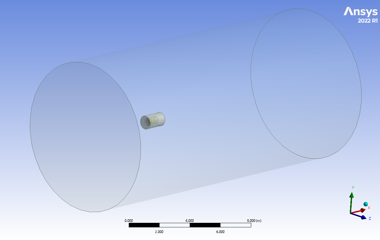
The present model in the 3-D domain of this simulation has been designed in ANSYS Design Modeler. The domain contains a velocity inlet, pressure outlet, and wall for the intake wall and side for the far field.
The meshing of this present model has been generated by ANSYS Meshing software. The mesh grid is unstructured; the total cell number is 16,635,982 elements.
Methodology: High-Bypass Turbofan Engine Fan Section Simulation
For modeling turbulence, the k-omega SST model was used, which simulates the intake at the operational point with a velocity of 0.8 mach number.
Also, the MRF method is used to define turbofan rotation.
Conclusion
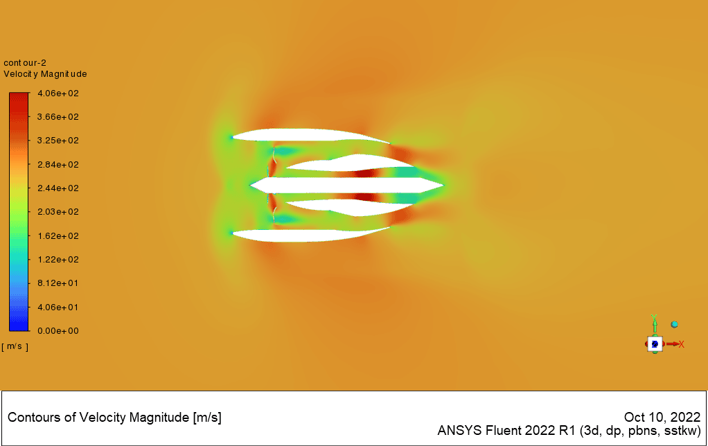
According to the speed contour in the middle of the engine, this simulation shows how the flow speed changes in different body profiles. At first, after the fan, the flow enters the bypass section and its speed increases, and finally, after passing through the bottleneck at the outlet, it reaches its maximum speed.
After passing through the fan, the core current of the engine increases and reaches its maximum in the combustion chamber, then when it reaches the turbine, its speed decreases, and it exits the outlet at a lower speed. These two outflows are mixed and reach a speed almost equal to the input speed
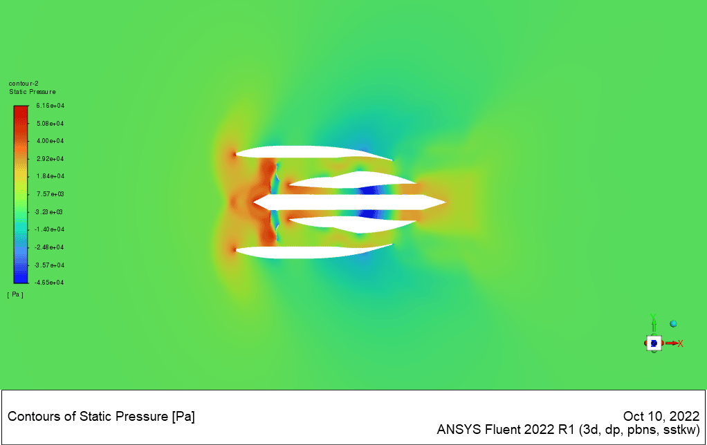
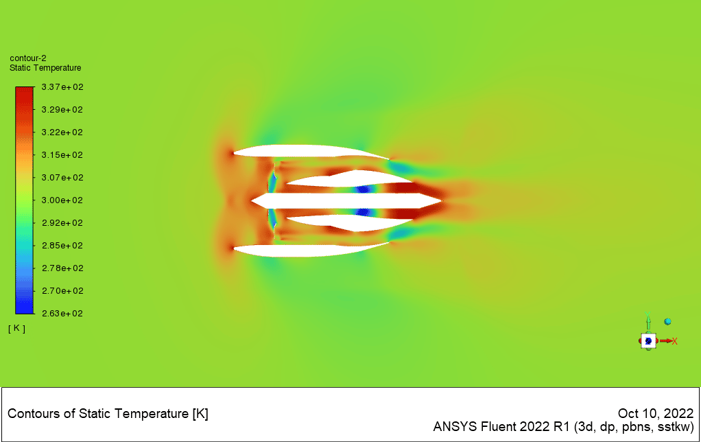
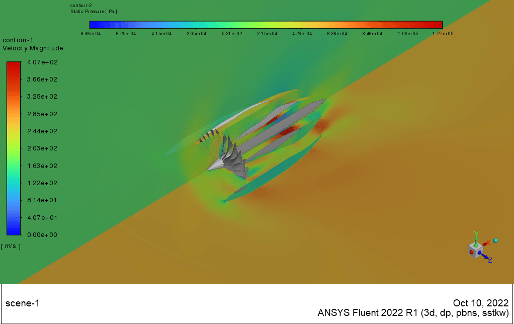
The temperature contour indicates the overall temperature increase in the engine environment. This increase in temperature is due to the increase in pressure due to the movement of the vanes, which is also noticeable in the static pressure contour.
The pressure contour is also due to increased pressure in front of the fan and bypass channels. Therefore, by summarizing these three diagrams, you can get a good view of how the fan works in a turbofan engine




Leila Schuppe –
I am thrilled with the level of detail in the high-bypass turbofan engine simulation! It really helps to visualize the airflow and understand the mechanism better. Great job on structuring a complex simulation into an understandable and comprehensive learning tool.
MR CFD Support –
Thank you for your kind review! We are delighted to hear that our simulation on the high-bypass turbofan engine helped to enhance your understanding. It’s always our aim to provide clear and detailed simulations to aid learning. We appreciate your feedback!
Prof. Abdullah Wintheiser II –
The detail in the simulation analysis is very informative. Was the fuel consumption or thermal efficiency of the engine analyzed during this CFD simulation as well?
MR CFD Support –
Given that the simulation focused on the airflow dynamics and the mechanical aspects of the high-bypass turbofan engine rather than the full engine thermodynamics, information on fuel consumption and thermal efficiency is not directly addressed in the provided simulation. These parameters typically require comprehensive modeling of the combustion chamber and the associated thermodynamic cycles, which go beyond the scope of the airflow simulation.
Jerrell Kling –
I found the explanation of the airflow in the bypass and the engine core fascinating. I’m truly impressed by how much detail the simulation provides about the changes in flow speed and temperature!
MR CFD Support –
Thank you very much for your kind words! We’re pleased to hear that you found the High-Bypass Turbofan Engine simulation detailed and informative. Our goal is to provide comprehensive insights into complex physical processes, and we’re glad we could convey that effectively. If you have any further questions or need assistance with your simulations, please feel free to reach out to us!
Sincere Johnston –
I’m thrilled by how the simulation captures flow speed changes at different engine profiles. Is it possible to obtain specific data on pressure changes at given points in the bypass and combustion chamber during operation for analysis purposes?
MR CFD Support –
Thank you for your positive feedback! Yes, it is certainly possible to obtain detailed data on pressure changes at specific points within the simulation. ANSYS Fluent allows users to monitor and record data at various locations throughout the computational domain, enabling precise analysis of pressure variation in areas like the bypass and combustion chamber during operation. This is useful for performance assessments and optimizing engine design.
Miss Josefina Ward –
Just went through the High-Bypass Turbofan Engine simulation training and I have to say, I’m thoroughly impressed by how accurately the simulation imitates real-world physics. The details in the airflows transition through the fan to the combustion chambers were especially intriguing. Nice work on modeling the engine dynamics!
MR CFD Support –
Thank you for your kind words and for taking the time to write a positive review of our High-Bypass Turbofan Engine CFD simulation training. We’re thrilled to hear that the simulation met your expectations and that the representation of airflows and engine dynamics was helpful and insightful. If you have any further feedback or need more in-depth training materials, feel free to reach out. We wish you the best in your continuing studies and application of CFD.
Emerson Ullrich –
The simulation of the High-Bypass Turbofan Engine sounds comprehensive! I’m curious, does the inclusion of temperature effects provide insights into the performance variations at different thrust levels?
MR CFD Support –
Thank you for your kind words and interest! In this particular simulation, we primarily focused on the airflow created by the fan and the speed and pressure changes throughout the engine. However, temperature effects are indeed very crucial in understanding the performance variations at different thrust levels, as they can significantly affect the engine’s efficiency and the resultant thrust. By analyzing temperature contours and pressure changes, one could infer how the engine performs under different operational conditions. If you wish, further simulations with more emphasis on thermal analysis could be conducted to delve deeper into those aspects.
Ms. Annabelle Aufderhar II –
The simulation sounded thorough, yet I’m curious, was this study conducted with a focus on how the temperature and pressure change throughout the bypass and core flow or just at specific profiles or parts within the engine?
MR CFD Support –
The study focused on understanding the variations of temperature and pressure throughout the bypass and core flow in the engine. Different contours and plots in the simulation represent the changes at various sections, providing a comprehensive analysis of the turbofan operation.
Mr. Arthur Lind –
This training course sounds very comprehensive. Can you tell me if it includes any video lectures or tutorials to help understand the complex airflow behaviors in the simulation?
MR CFD Support –
Yes, the training course includes detailed video lectures that cover the fundamentals of turbofan engine operation, the specifics of the simulation setup, including boundary conditions, and a step-by-step guide through the simulation process in ANSYS Fluent, facilitating an in-depth understanding of complex airflow behaviors within the turbofan engine.
Xzavier Zieme –
I’m impressed with the level of detail in the airflow and temperature simulation of this high-bypass turbofan engine. From the fan to the combustion chamber, interesting how well each aspect has been captured. The massive number of elements in the mesh must have contributed significantly to the accuracy of your findings!
MR CFD Support –
Thank you so much for your positive feedback! We’re glad to hear that you found the details in the simulation informative and noteworthy. The detailed mesh indeed plays a crucial role in achieving precise simulations of complex systems like a high-bypass turbofan engine. If you need any further information or have more questions, please don’t hesitate to ask. We appreciate your interest in our CFD training products.
Alanis Pollich –
The explanation was very enlightening, thank you for your great product!
MR CFD Support –
Thank you for your kind words! We’re thrilled to hear that our High-Bypass Turbofan Engine CFD Simulation has been helpful to you. If you have any further questions or need assistance with anything else, don’t hesitate to reach out. We’re here to help!
Seth Kub –
Does this simulation take into account the thermal aspects of the engine, like the temperature increase due to compression?
MR CFD Support –
The description focuses mainly on the airflow and speed changes through the engine but does mention that the temperature contour indicates an overall temperature increase in the engine environment. This suggests that although primary attention is on aerodynamic aspects, the simulation does reflect some level of thermal response due to compression and the motion of the vanes.
Marlen Becker –
The detail in your review about how the flow speed changes in different parts of the engine illustrates a comprehensive analysis. Do you think the k-omega SST model was the best choice for this simulation, or could other turbulence models potentially improve the accuracy of the results?
MR CFD Support –
Thank you! The k-omega SST is often chosen for aerospace applications because it effectively captures boundary layer flows and separate flows, which are common in turbofan engines. It’s a robust choice for the described simulation. However, there are various other models available, and the optimal choice may depend on factors such as computational resources, required accuracy, and specific flow phenomena of interest. The choice of a more accurate or specialized turbulence model could potentially result in a different simulation outcome.
Howell Spencer I –
The tutorial was incredibly detailed and thorough. Watching the simulation’s response to various profiles along the engine provided real insight into high-bypass turbofan behaviors. Sterling work!
MR CFD Support –
Thank you for your positive feedback! We’re thrilled to hear that our tutorial on high-bypass turbofan engine simulation was informative and helpful. Your experience with the detailed analysis of flow speed and temperature changes is exactly what we aim to provide to our users. If you have any further questions or need additional information, don’t hesitate to ask. We’re here to help!
Dalton Kihn –
I loved the detailed breakdown of different speeds and pressures throughout the engine! The visual aids helped me understand the complex airflow dynamics in the turbofan engine.
MR CFD Support –
Thank you for your positive feedback! We’re thrilled to hear that our simulation visuals and detailed explanations enhanced your understanding of turbofan engine operations. Your satisfaction with our CFD training product is very important to us, and we strive to provide the best learning experience through our simulations. If you have any further questions or need more information, feel free to reach out to us.
Elwyn Wolff –
The detail on the simulation process and results is insightful! This simulation offers a comprehensive understanding of the workings of a high-bypass turbofan engine. The use of the k-omega SST model and MRF method sounds very appropriate for such aerodynamic complexities. Well done on successfully delivering these complex aerodynamic phenomena into understandable results.
MR CFD Support –
Thank you for your positive feedback on our CFD simulation of the High-Bypass Turbofan Engine. We are delighted to know that you found the details insightful and the simulation process comprehensive. Ensuring a thorough understanding of the complex aerodynamics involved in engine operation is at the core of our training offer. Your compliments are much appreciated, and we’re pleased the results were delivered in a format that enhanced your knowledge of fan operations in turbofan engines.
Chad Lehner –
The training materials provided a clear understanding of the bypass flow behavior in a high-bypass turbofan engine. The use of both the k-omega SST model for turbulence and the MRF method for rotation really helped me visualize the airflow processes within the engine. I especially appreciated the detailed examination of how speed and pressure changed within the different sections, which clarifies the fan’s role in the engine’s operation.
MR CFD Support –
Thank you so much for your positive review! We are thrilled to hear that our CFD training materials for the high-bypass turbofan engine in ANSYS Fluent were helpful for you. It’s great that the combination of turbulence modeling and rotational definitions provided a clear picture of the engine’s internal airflow. If you have any further questions or need more insights into our products, feel free to reach out. Your success is our priority, and we’re here to assist you with any advanced simulations you might tackle in the future!
Aliya Predovic –
I am highly impressed with the detail of the simulation work. The ability to visualize airflow and temperature changes inside the high-bypass turbofan engine has deepened my understanding of its functionality. How the fan influences the bypass section and core flow elucidated the dynamics of commercial jet engines nicely. A special nod to the clarity of presentation of pressure, speed, and temperature aspects. Bravo to the MR CFD team for such an insightful simulation study!
MR CFD Support –
Thank you kindly for your enthusiastic compliment. We’re thrilled to hear our High-Bypass Turbofan Engine CFD Simulation met your expectations and provided you with a deeper insight into the engine’s workings! It’s our pleasure to deliver comprehensive studies and clear presentations for our learners. Your words truly motivate the MR CFD Team to continue delivering quality educational content. We appreciate your time writing this review and are pleased to have satisfied your quest for knowledge!
Prof. Braxton Schaden IV –
I’ve just finished the High-Bypass Turbofan Engine CFD Simulation course. The level of detail and depth of knowledge offered was staggering! The way airflow and pressure changes were depicted through the simulation helped me really understand the complexities of high-bypass turbofan engines. Thank you!
MR CFD Support –
Thank you for your kind feedback! We’re delighted to know that our simulation course on the High-Bypass Turbofan Engine provided you with a detailed understanding of its workings. We strive to create comprehensive learning experiences and it’s rewarding to hear that we’ve achieved that. If you have any further interests or need assistance with any other simulation projects, we’re always here to help!