
Supersonic Jet Ramped Intake CFD Simulation Training
$100.00 Internship
- The problem numerically simulates the Supersonic Jet Ramped Intake using ANSYS Fluent software.
- We design the 3-D model with the Design Modeler software.
- We mesh the model with ANSYS Meshing software, and the element number equals 1278343.
- We have used the density-based solver due to the compressibility.
To Order Your Project or benefit from a CFD consultation, contact our experts via email (info@mr-cfd.com), online support tab, or WhatsApp at +44 7443 197273.
There are some Free Products to check our service quality.
If you want the training video in another language instead of English, ask it via info@mr-cfd.com after you buy the product.
Description
Supersonic Jet Ramped Intake Simulation, ANSYS Fluent CFD Training
In this project, we have simulated a supersonic jet ramped inlet using ANSYS Fluent software. With the development of jet engines and the subsequent ability of aircraft to travel at supersonic speeds, it was necessary to design inlets to provide the flow required by the engine over a wide operating envelope and to provide air with a high-pressure recovery and low distortion.
These designs became more complex as aircraft speeds increased to Mach 3.0 and Mach 3.2, design points for the XB-70 and SR-71, respectively. The inlet is part of the fuselage or part of the nacelle.
The ramped or angled intakes are designed so that the angled surfaces form the shock waves, and the uniform and undisturbed flow enters the channel and the engine. The geometry of the cross-section changes as it moves along the channel to give shape to the flow.
In this case, it is modeled from an Intek with a ramp, and its model is taken from the geometry of the F-15 Intak. And this inlet is placed in a supersonic flow with a speed of Mach 1.4, and the changes in speed and pressure and the speed profile along the channel are investigated.
The present model in the 3-D domain of this simulation has been designed in ANSYS Design Modeler. The part contains a velocity inlet, pressure outlet, and wall for the intake wall and side for the far field.
The meshing of this present model has been generated by ANSYS Meshing software. The mesh grid is unstructured; the total cell number is 1278343 elements.
Methodology
In this simulation, the density-based solver has been used. For modeling turbulence, the k-omega SST model was used. In this simulation, the intake is simulated at the operational point with a velocity of 1.4 mach.
Supersonic Jet Ramped Intake Conclusion
In the simulation results, according to the Mach number contour, it is clear how oblique waves and expansion fans are formed in the intake and inside the intake channel.
These shock waves at the beginning of the air inlet make the flow speed subsonic and make the flow uniform, and inside the channel, it acts like a converging and diverging nozzle. It is also evident in the performance of the pressure and temperature contours and how it affects them.
For a more detailed analysis, we look at the speed contours in different intake areas and find out how this wall form has made the flow speed uniform along it.
The pressure contour along the range also shows how the intake opening pressure drops and then recovers during it. This causes the engine to remain in ideal working condition and not suffer from compressor stall.

Reviews
You must be logged in to post a review.
Related products
-
Sale

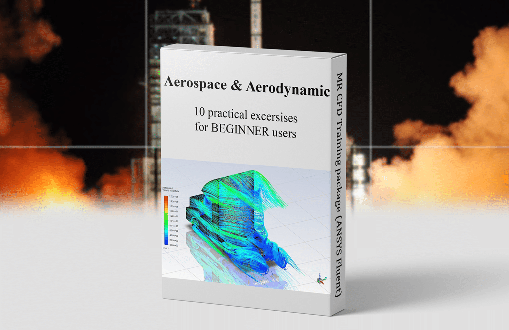
Aerodynamic and Aerospace Training Package for Beginners, 10 Learning Products
Original price was: $840.00.$299.00Current price is: $299.00. Internship

Ms. Isobel Willms Jr. –
I am thrilled with the results attained by the simulation and would like to know how long it took to complete this detailed simulation?
MR CFD Support –
Thank you for your kind words! We’re glad to hear you are pleased with the simulation results. The duration of the simulation can vary depending on many factors including computational power, complexity of the geometry, and the specificity of the assessed conditions. Normally, such simulations can take from a few hours to several days. Would you be interested in any specific aspects of computational duration or efficiency for this project?
Jonatan Botsford –
The results are fascinating! How were distancing conditions from the far field managed to ensure accurate simulation of supersonic flow?
MR CFD Support –
In the simulation of supersonic flow, the far field boundary conditions were managed carefully to guarantee minimal reflection of shock waves and disturbances. By appropriately setting outflow conditions and ensuring that the computational domain is large enough, interference with the behavior of the intake can be minimized to achieve accurate results.
Peggie Koelpin –
Fantastic learning experience! The Supersonic Jet Ramped Intake CFD Simulation Training was insightful and thoroughly explained the complexities of ram intake at high speed, shockwaves, and the role of back-pressure. Following the steps and understanding the flow transition from supersonic to subsonic was captivating. Highly recommended for anyone keen on advanced aerodynamics or seeking to grasp supersonic flow dynamics.
MR CFD Support –
Thank you for your positive feedback! We are thrilled to hear that you found the training insightful and that it enhanced your understanding of supersonic aerodynamics. It’s great to know the material was presented in a way that captured your interest and made learning these advanced concepts enjoyable. We appreciate your recommendation and are delighted that you had a fantastic learning experience.
Dr. Joany Brekke –
I used this training for my aerospace engineering studies and the clarity on how shock waves and expansion fans influence the intake operation was remarkable. It really helped me understand the fundamental aerodynamics at play in supersonic jet engines!
MR CFD Support –
Thank you for your feedback! We’re delighted to hear that our training material was instrumental in enhancing your understanding of aerodynamics in the context of supersonic jet engines. It’s always inspiring to learn how our products help in academic success.
Dr. Kip Heller –
The way that the simulation captures oblique waves and expansion fans is fascinating. How accurately does this model replicate real-world intakes in terms of shock wave formation and pressure recovery?
MR CFD Support –
Thank you for the compliment! Our simulation is designed to capture critical details accurately, and we’re pleased to hear the phenomena of shock waves and expansion fans are well represented. We strive to closely match real-world performance, allowing for valuable insights into pressure recovery and intake efficiency. If you’d like more precise validation data or case study comparisons, we would be glad to provide additional information.
Prof. Luis King V –
I am very impressed with the way the shock waves and the flow behavior was displayed in the CFD simulation. The attention to detail for capturing the phenomena at supersonic speeds within this type of jet engine intake was fantastic!
MR CFD Support –
We’re delighted to hear that you appreciate the detail and accuracy put into the Supersonic Jet Ramped Intake CFD Simulation. Our goal is always to provide insightful and realistic simulations that help understand complex fluid dynamics. Thank you for your positive feedback!