Jet Fan Application in a Tunnel Considering a Car Explosion, CFD Simulation ANSYS Fluent Training
$200.00 Student Discount
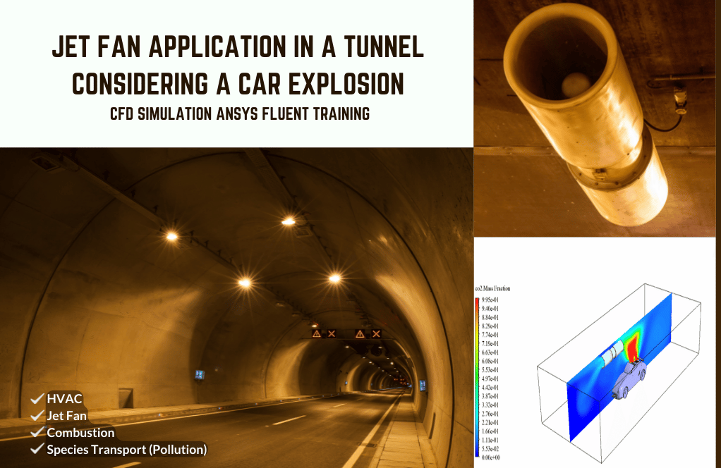
The present simulation is about a Jet Fan Application in a Tunnel Considering a Car Explosion via Ansys Fluent.
Click on Add To Cart and obtain the Geometry file, Mesh file, and a Comprehensive ANSYS Fluent Training Video.To Order Your Project or benefit from a CFD consultation, contact our experts via email ([email protected]), online support tab, or WhatsApp at +44 7443 197273.
There are some Free Products to check our service quality.
If you want the training video in another language instead of English, ask it via [email protected] after you buy the product.
Description
Jet Fan Application in a Tunnel Considering a Car Explosion Project Description
The present simulation is about a car explosion in the tunnel via ANSYS Fluent. This project assumes that a car will ignite due to a gasoline leak and contact with the airflow. This car is crossing the interior of a tunnel. The explosion ignited a fire and released carbon dioxide into the tunnel. Since the tunnel is closed, carbon dioxide fills the space and can’t disappear in the free air.
This phenomenon is dangerous for other cars and passing citizens. Therefore, they use equipment called jet fans on the tunnel’s roof. These jet fans have fans that suck carbon dioxide and other pollutants to the tunnel’s roof. These gases are sucked into the jet fans and are directed out through these jet fans. So, the primary use of these jet fans is to prevent excessive polluting gas emissions.
For this modeling, it is assumed that the combustion reaction has already occurred. Therefore, there is no need to define the combustion reaction and only model the emission of carbon dioxide from combustion.
The species transport model is used to define CO2 and air. Airflow enters the tunnel at a temperature of 300 K and a velocity of 1.5 m/s. At the car’s rear, a specific volume is distinguished as the source of the explosion.
For this zone, a source for CO2 emissions and heating energy due to combustion is defined. CO2 is defined at a rate of 10,000 kg/m3.s and thermal energy at 1000 W/m3. Also, the fan boundary condition defines a pressure jump in the jet fan section.
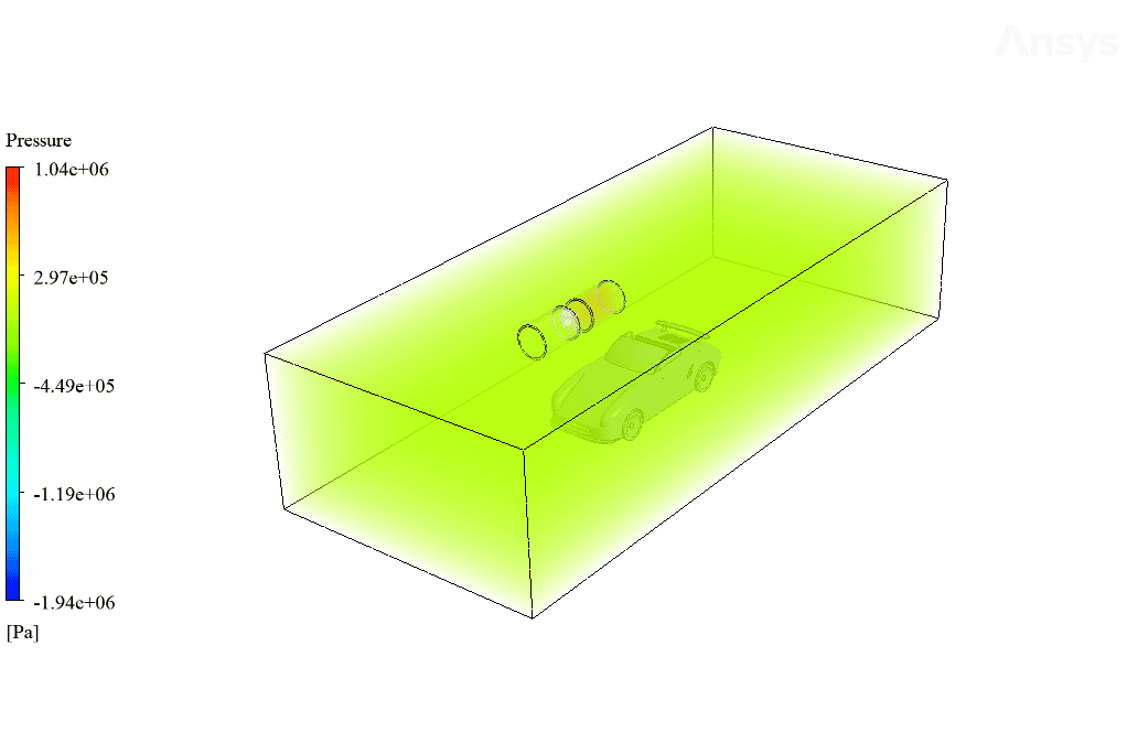
This pressure jump causes the surrounding air to be sucked into the jet fan. The pressure jump is defined as 1000000 Pa.
Geometry & Mesh
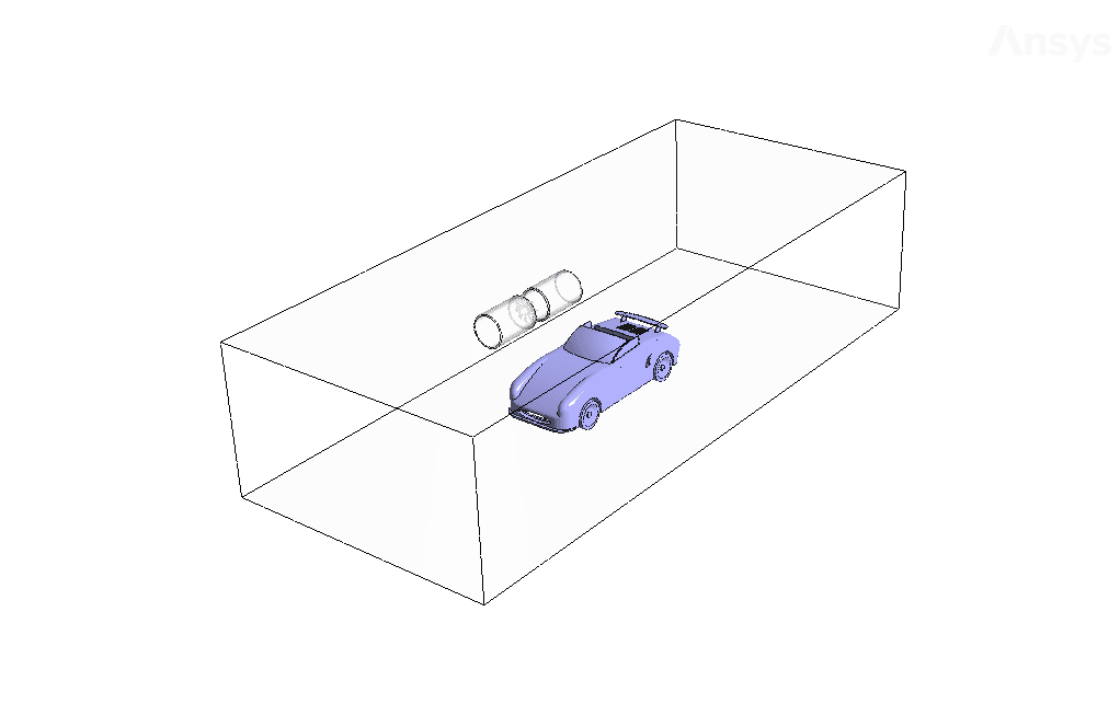
The present geometry is designed in a 3D model via Design Modeler. The computational zone is the interior of a tunnel. Inside the tunnel, a car is modeled on the floor and a jet fan on the roof. Also, a specific volume on the car’s rear for the source of the explosion and a certain level in the initial part of the jet fan is modeled as the fan.
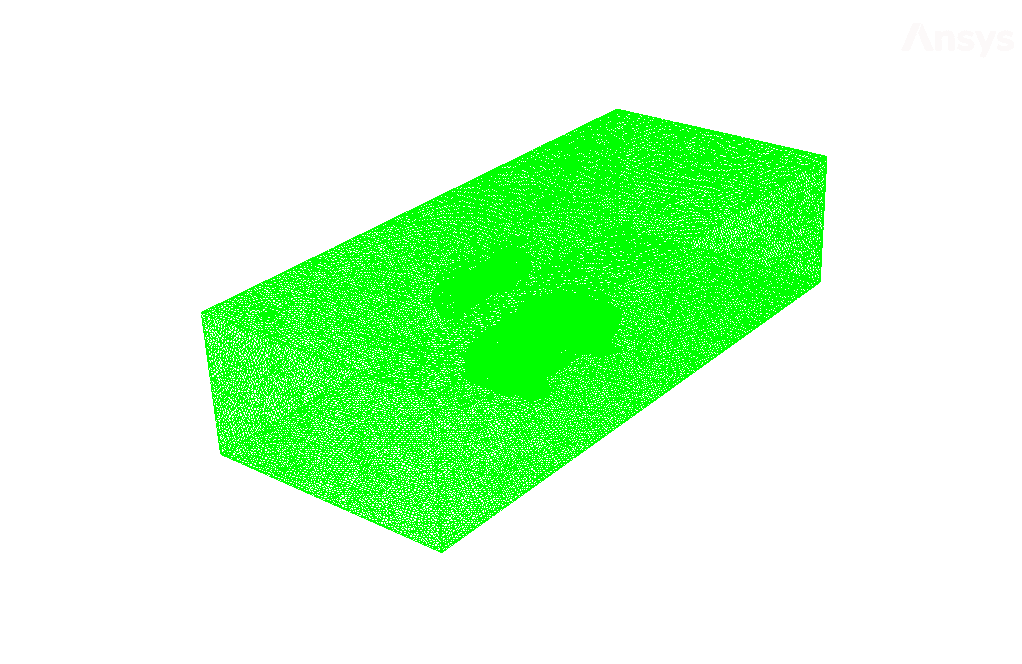
The mesh of the present model has been done via ANSYS Meshing. Mesh is done unstructured, and the number of production cells equals 598396.
Set-up & Solution
Assumptions used in this simulation :
- Pressure-based solver is used.
- The present simulation is steady.
- The effect of gravity on the model is ignored.
| Models | |||
| Viscous | k-epsilon | ||
| k-epsilon model | RNG | ||
| near wall treatment | standard wall function | ||
| Species | Species Transport | ||
| number of volumetric species | 2 (air & CO2) | ||
| Energy | On | ||
| Boundary conditions | |||
| Inlet | Mass Flow Inlet | ||
| velocity magnitude | 1.5 m.s-1 | ||
| temperature | 300 K | ||
| CO2 mass fraction | 0 | ||
| Outlet | Pressure Outlet | ||
| gauge pressure | 0 Pascal | ||
| Wall | Wall | ||
| wall motion | stationary wall | ||
| heat flux | 0 W.m-2 | ||
| Methods | |||
| Pressure-Velocity Coupling | SIMPLEC | ||
| pressure | Second-order | ||
| momentum | First-order upwind | ||
| turbulent kinetic energy | First-order upwind | ||
| turbulent dissipation rate | First-order upwind | ||
| CO2 | First-order upwind | ||
| energy | First-order upwind | ||
| Initialization | |||
| Initialization methods | Standard | ||
| velocity magnitude | 1.5 m.s-1 | ||
| temperature | 300 K | ||
| CO2 mass fraction | 0 | ||
Jet Fan Application in a Tunnel Considering a Car Explosion Result
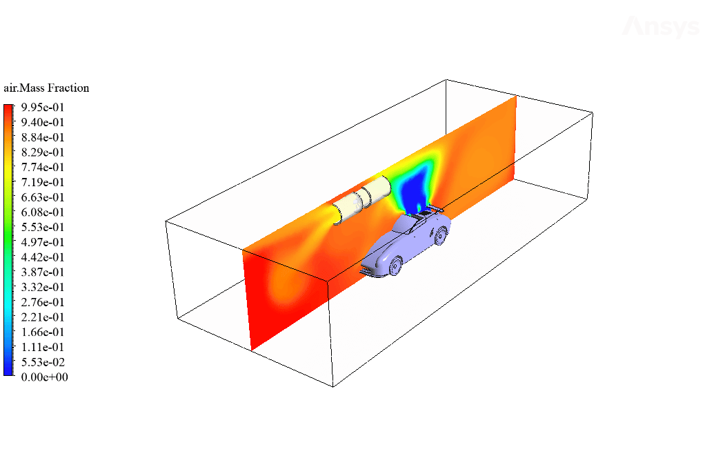
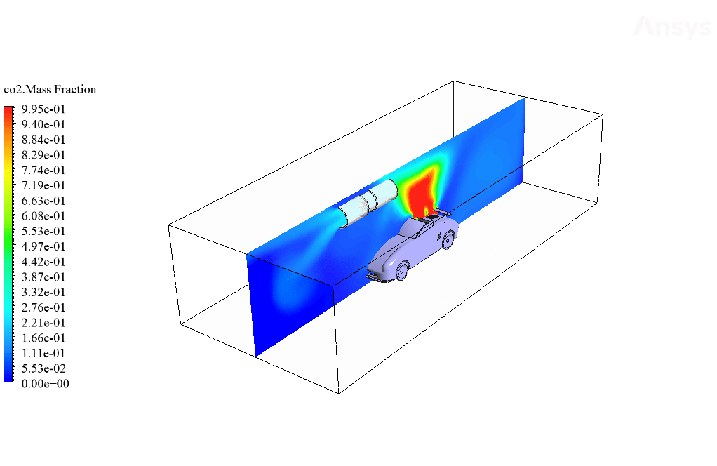
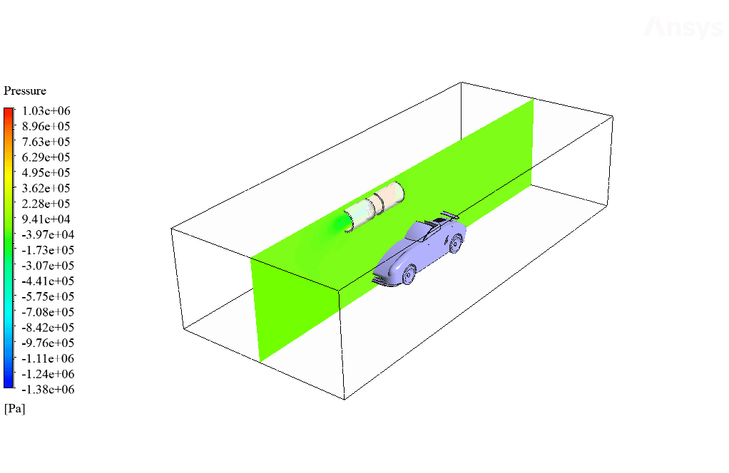
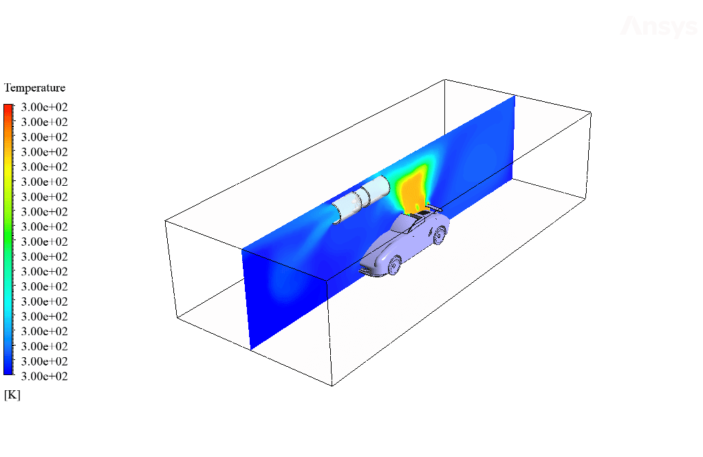
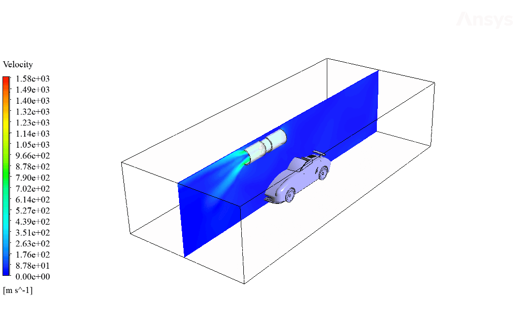
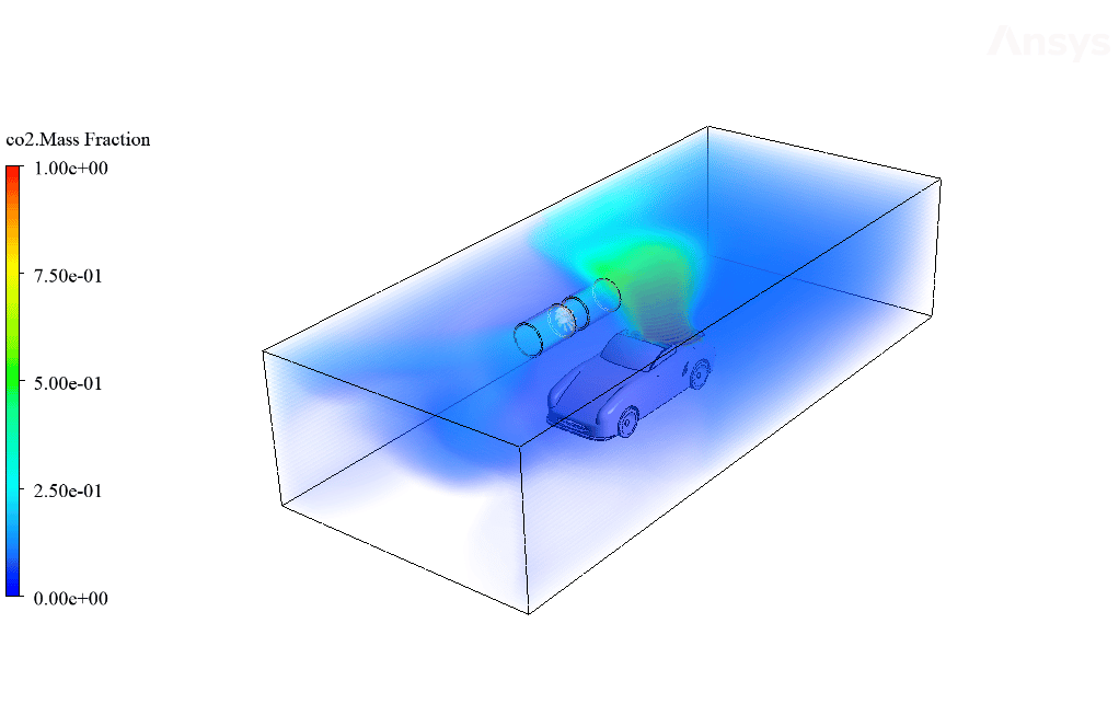
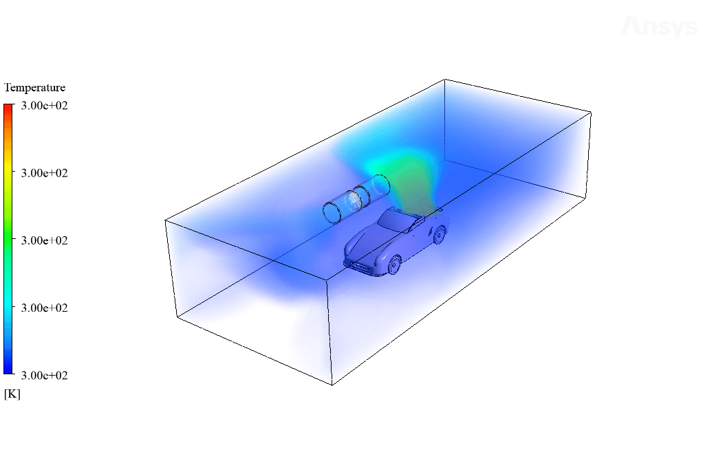
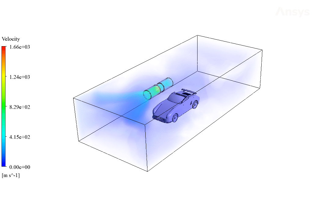
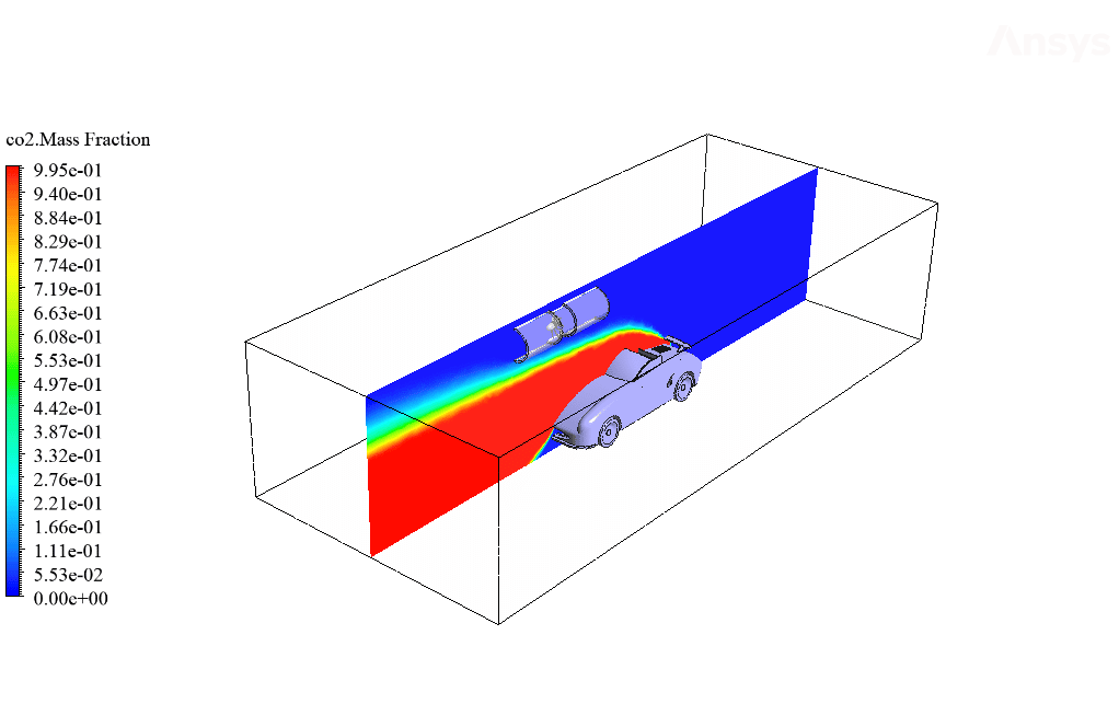
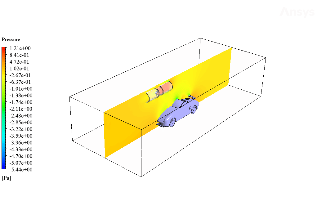
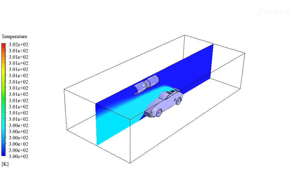
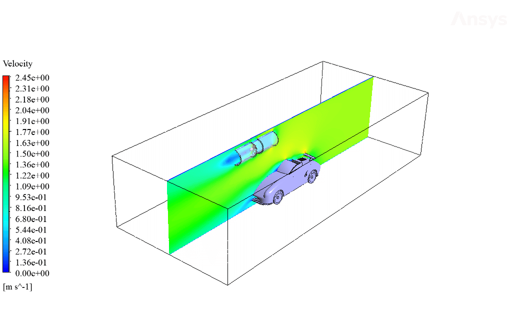
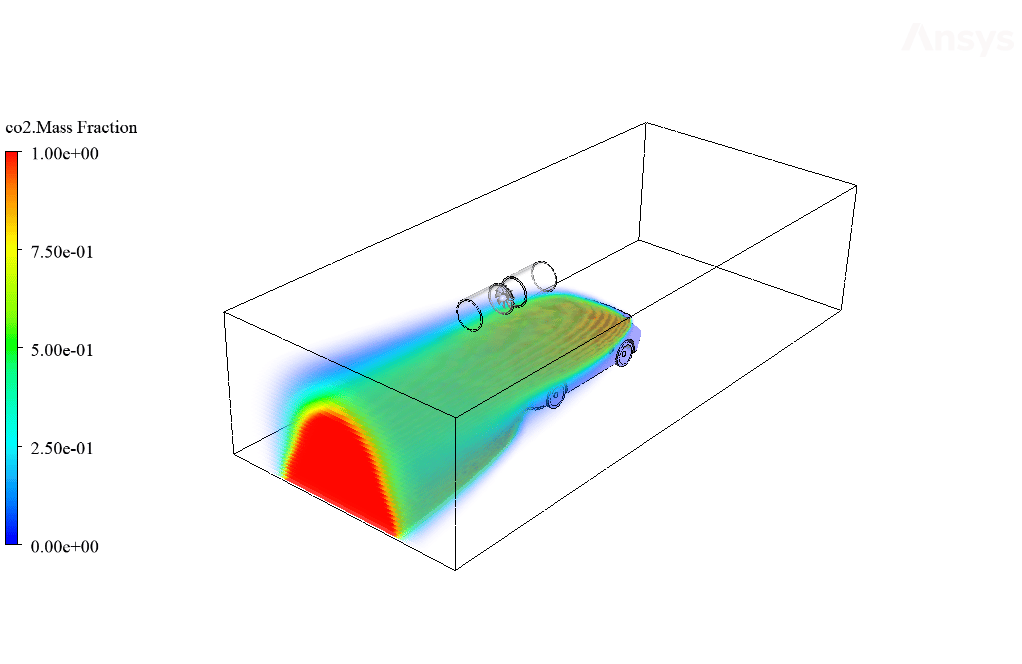
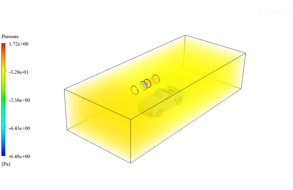
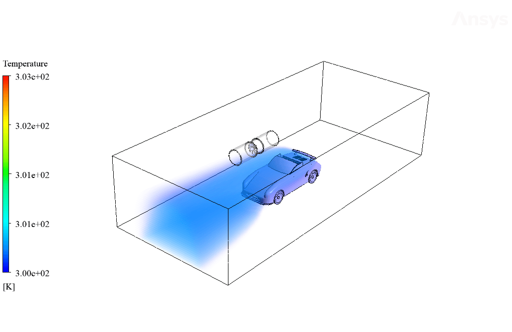
After calculation, 2D and 3D contours related to pressure, velocity, temperature, and mass fraction of air and CO2 are obtained. The results show that the jet fan system is working correctly. The explosion occurs at the car’s rear, generating significant heat and emitting CO2.
The presence of these jet fans causes this CO2 gas to move upwards and be sucked into the jet fans. Therefore, this mechanism prevents the spread of CO2 and pollutants in the tunnel’s interior. Also, to better compare the results and evaluate the performance quality of the jet fans, this modeling was performed again without using jet fans.
All simulation conditions are similar to the previous model; The difference is that the fan boundary condition is not used in the initial part of the jet fan. The results show that when the jet fan does not operate, CO2 gas fills the tunnel’s interior.
Miss Elnora Mraz I –
I’m impressed by the level of detail in the simulation of the jet fan’s effectiveness. It gives me confidence that this could be useful for real-world applications. Well done!
MR CFD Support –
Thank you for your kind words! We’re glad to hear that the detailed simulation results could inspire confidence for practical applications. It’s always a pleasure to receive positive feedback. If there’s anything more you’re interested in or any further information you need, don’t hesitate to reach out!
Maurine Ferry –
The explanation was quite clear, and the various aspects of using jet fans for safety and pollution control in a tunnel environment were interesting.
MR CFD Support –
Thank you for your kind words! We take pride in providing comprehensive and detailed simulations to our users. We are thrilled to hear that you found the materials clear and the jet fan application intriguing. Should you have any more questions or need further explanations, feel free to ask. We are here to help!
Jesse Tremblay –
This simulation seems complex. Were you able to capture all the post-explosion effects within the tunnel accurately, given various assumptions in the initial set-up, or were there some limitations in predicting the aftermath of a car explosion?
MR CFD Support –
The simulation does make certain assumptions for feasibility and computational practicality, such as steady-state conditions and neglecting gravity. While it captures the general behavior of CO2 distributions and the effectiveness of the jet fans pretty well, there could indeed be limitations, particularly in the accurate representation of transient phenomena immediately following the explosion. However, the primary objectives, such as pollutant dispersion control by jet fans, have been effectively modeled and analyzed.
Teresa Kreiger DDS –
The jet fans really seem to do their job effectively based on your results. Great to see that safety measures like this could have such a strong real-world application in emergency scenarios. Keep up the good work!
MR CFD Support –
Thank you for acknowledging the effectiveness of the jet fan simulation in our project scenario. We are glad to hear that you appreciate the practical implications of our CFD analysis and its potential contribution to safety measures. Your feedback is very motivating for our team!
Trenton Hand –
The simulation result summary is insightful. Great to see it considers a critical safety scenario. Is there an analysis on how different velocities of airflow in the tunnel affect the efficacy of the jet fans in clearing CO2?
MR CFD Support –
Thank you for your positive feedback. The simulation specifically focuses on the airflow velocity entering the tunnel at 1.5 m/s. An analysis of various airflow velocities would be interesting to evaluate the jet fans’ efficacy under different conditions, but this simulation maintained a constant velocity to observe the outcome in a controlled environment.
Dr. Aliyah Romaguera IV –
The description of how the jet fan system functions after a car explosion in the tunnel was truly impressive. It showcased the intricacy of CFD applications in safety analysis and how valuable such simulations can be in designing emergency responses.
MR CFD Support –
Thank you for your commendation! We’re delighted to hear that our simulation on the application of jet fans during emergencies was informative and helped demonstrate the crucial impact of rigorous CFD analyses in designing safety measures. Ensuring comprehensible and valuable training material is our priority, and customer feedback like this is greatly appreciated.
Beatrice Jacobi –
This product looks like it provided comprehensive training on how to simulate a complex scenario like a car explosion in a tunnel. Considering the details provided, it seems like everything from initial set-up to final results has been covered effectively. Great job on illustrating the application and impact of jet fans in such scenarios!
MR CFD Support –
Thank you for your kind words! I’m delighted to hear that the training provided a comprehensive understanding of simulating challenging scenarios and the efficacy of jet fans. We strive to offer detailed and practical learning experiences. If you have any more feedback or need further assistance, feel free to reach out!
Prof. Renee Kerluke –
The project illustrates the efficient use of jet fans in clearing the smoke after a car explodes in a tunnel. Remarkable CFD application to enhance safety mechanisms!
MR CFD Support –
Thank you for your kind words. We are glad to hear that our simulation project met your expectations and provided valuable insights into safety applications using CFD. Your feedback is much appreciated!
Dr. Kade Klein V –
The results were fantastic and enlightening. The simulation clearly demonstrated the jet fan’s efficiency. Great job!
MR CFD Support –
Thank you for your kind words. We’re thrilled to hear that you found the simulation results enlightening and that they effectively demonstrated the jet fan’s functionality. Your feedback is greatly appreciated!
Carolina King –
The detail on the species transport model usage is wonderful! Understanding carbon dioxide management in tunnel safety is crucial.
MR CFD Support –
Thank you! We’re glad the explanation on using the species transport model for CO2 management in tunnel safety situations was insightful and appreciated.
Mr. Deven Beer Jr. –
The training was comprehensive and clear. The way jet fans’ efficiency was showcased by comparing scenarios with and without jet fans was particularly helpful for understanding their role in tunnel safety.
MR CFD Support –
Thank you for your kind words! We’re delighted to hear that our ANSYS Fluent training for Jet Fan Application in a Tunnel was thorough and insightful. Your understanding of the importance of jet fans in maintaining tunnel safety is exactly what we aim for. Should you have further inquiries or need additional information on our CFD products, feel free to reach out. We’re here to help!
Marcelle Lockman –
Very impressed with the detail and clarity of this CFD simulation by MR CFD! It gave a great understanding of the jet fan’s impact in the face of a tunnel emergency.
MR CFD Support –
Thank you for your positive feedback! We’re glad that our simulation provided clear insights, and it’s great to hear that the details helped enhance understanding of the jet fan application in critical scenarios.
Fiona Rowe DVM –
The course wonderfully detailed the use of jet fans in emergency scenarios! Great work. Could you please share which software versions are compatible with the course content?
MR CFD Support –
Thank you for your positive feedback! The course generally emphasizes using ANSYS Fluent to simulate the scenario. Any recent version of ANSYS Fluent, typically from the last two or three releases, should suffice as the fundamental simulation principles taught in the course should remain consistent across these versions.
Dr. Fae Okuneva V –
Fantastic learning resource! The ‘Jet Fan Application in a Tunnel Considering a Car Explosion’ simulation was both intricate and realistic. The level of detail in the setup provided a clear picture of each process step. It was particularly insightful to see the species transport model in action and how the jet fans effectively remove pollutants. The stark comparison between the scenario with and without jet fans is a testament to the importance of these systems in tunnels. Great work team MR CFD on an exceptional training module!
MR CFD Support –
Thank you for the cheerful review! It’s terrific to hear that you found the Jet Fan Application simulation to be educational and informative. We’re glad that the details on the species transport model and the effectiveness of jet fans in pollution control were helpful to your learning. Your positive feedback motivates us to keep providing high-quality training content. We look forward to offering you more valuable learning experiences in the future!
Ariel Welch –
Fantastic representation of an emergency scenario! The simulation’s detail on jet fan efficiency in dispelling CO2 post-explosion is invaluable for safety assessments.
MR CFD Support –
We greatly appreciate your recognition of the effort put into running a simulation with such critical applications. Ensuring tunnel safety through accurate CFD analysis is vital, and we’re glad our product reflected this importance. Thank you for your positive feedback!
Dr. Brigitte Ernser –
The training explains the simulation very well, its impact is impressive on my understanding of CFD applications in emergency scenarios. It beautifully demonstrates the vital role of jet fans.
MR CFD Support –
Thank you for your positive feedback on the jet fan simulation training! We’re delighted to hear that it has been instrumental in enhancing your understanding of CFD in real-world applications, especially in managing tunnel emergencies. Your kind words inspire us to continue delivering valuable learning experiences.
Mr. Hal Satterfield –
This is absolutely fascinating! The caliber of the project is astounding and it provides such an incredibly detailed visualization of the mechanics behind handling a car explosion scenario within a tunnel. Using jet fans to manage and mitigate the consequence of a car fire is a commendable use of simulation to ensure safety and proper ventilation. Great job indeed!
MR CFD Support –
We are thrilled that you find the simulation so impressive and useful. It’s wonderful to hear that our detailed approach to modeling the tunnel explosion scenario and jet fan application was well-received. Maintaining safety and finding effective solutions for such critical incidents is of utmost importance to us. Thank you for taking the time to acknowledge our efforts with your praise!
Immanuel Mann –
This training helped me understand the importance of jet fans in emergency situations within tunnels. Did jet fans significantly reduce CO2 concentrations compared to the scenario without jet fans?
MR CFD Support –
Yes, the simulation results showed that the jet fans are very effective in reducing CO2 concentrations. When the jet fans operate, they effectively move the CO2 upwards and suck it away, preventing it from spreading throughout the tunnel.