Duct Effect on HAWT Performance, CFD Simulation ANSYS Fluent Training
$180.00 Student Discount
In this project, a horizontal axis wind turbine (HAWT) is modeled in two different cases via Ansys Fluent.
Click on Add To Cart and obtain the Geometry file, Mesh file, and a Comprehensive ANSYS Fluent Training Video.To Order Your Project or benefit from a CFD consultation, contact our experts via email ([email protected]), online support tab, or WhatsApp at +44 7443 197273.
There are some Free Products to check our service quality.
If you want the training video in another language instead of English, ask it via [email protected] after you buy the product.
Description
Duct Effect on HAWT Performance Problem Description
In this project, Duct Effect on HAWT Performance is simulated in two different cases via Ansys Fluent. Once, without implementing any duct, and in another case, a duct is installed. The study aims to investigate the effect of the duct on turbine performance. Plus, the multi-reference frame (MRF) module is used, and the tip-speed ratio is 2.5.
Geometry & Mesh
The 3D geometry is modeled in Ansys Design Modeler software for both cases. Also, the mesh grid is carried out using Ansys Meshing software. Furthermore, an unstructured grid and boundary layer is generated in the first place and then transformed into polyhedron elements to decrease the computational cost. Therefore, 10506896 & 12216335 elements established the fluid domain, respectively.
CFD Simulation
Several assumptions have been considered to simulate HAWT, including:
- The simulation is Steady in order to investigate the performance in a working manner.
- The pressure-based solver type was used due to the incompressibility of the working fluid.
- Gravitational acceleration effects were ignored.
The following table represents a summary of the solution:
| Models(Viscous) | ||
| Viscous | K-w | SST |
| Materials | ||
| Fluid | Definition method | Fluent database |
| Material name | Air | |
| Cell zone condition | ||
| Material name | Air | |
| Frame Motion | -2000rpm | |
| Boundary condition | ||
| Inlet | Type | Velocity inlet |
| Velocity magnitude | 5m/s | |
| Turbulent intensity | 5% | |
| Turbulent viscosity ratio | 10 | |
| Outlet | Type | Pressure-outlet |
| Gauge Pressure | 0 | |
| Blade-turbine
Nuzzle Hub Tunnel |
Type | Wall
(Stationary – No-slip condition) |
| Solver configuration | ||
| Pressure-velocity coupling | Scheme | Coupled |
| Spatial Discretization | Gradient | Least squares cell-based |
| Pressure | PRESTO! | |
| Momentum | First-order upwind | |
| Turbulent kinetic energy | First-order upwind | |
| Turbulent dissipation rate | First-order upwind | |
| Initialization | Initialization methods | Standard Initialization |
| Run Calculation | Number of Iterations | 2500 |
Duct Effect on HAWT Performance Results
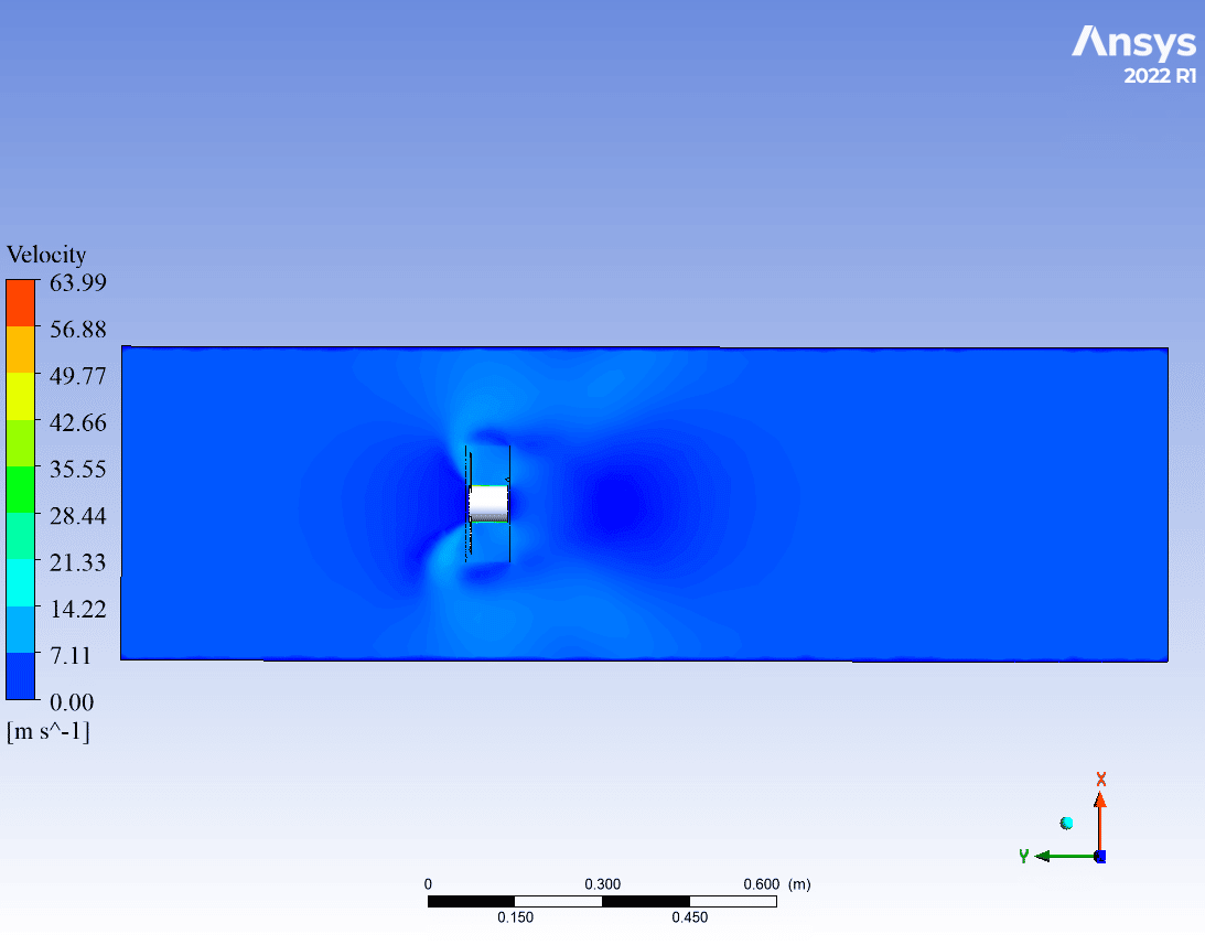
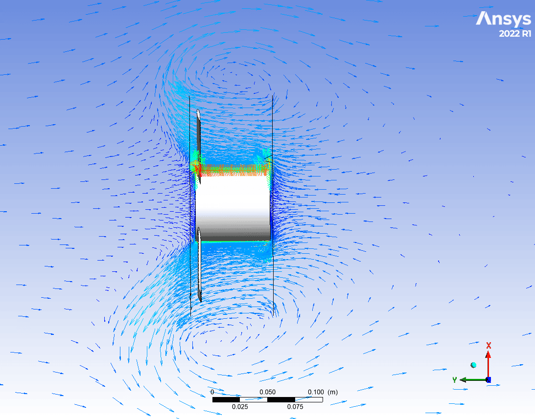
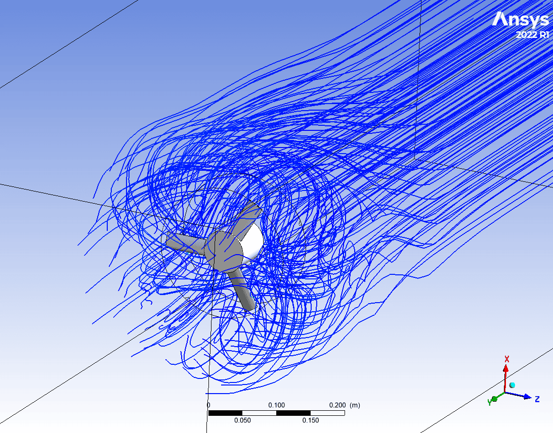
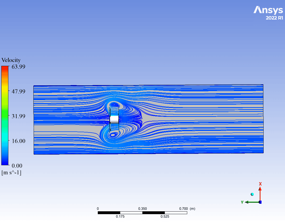
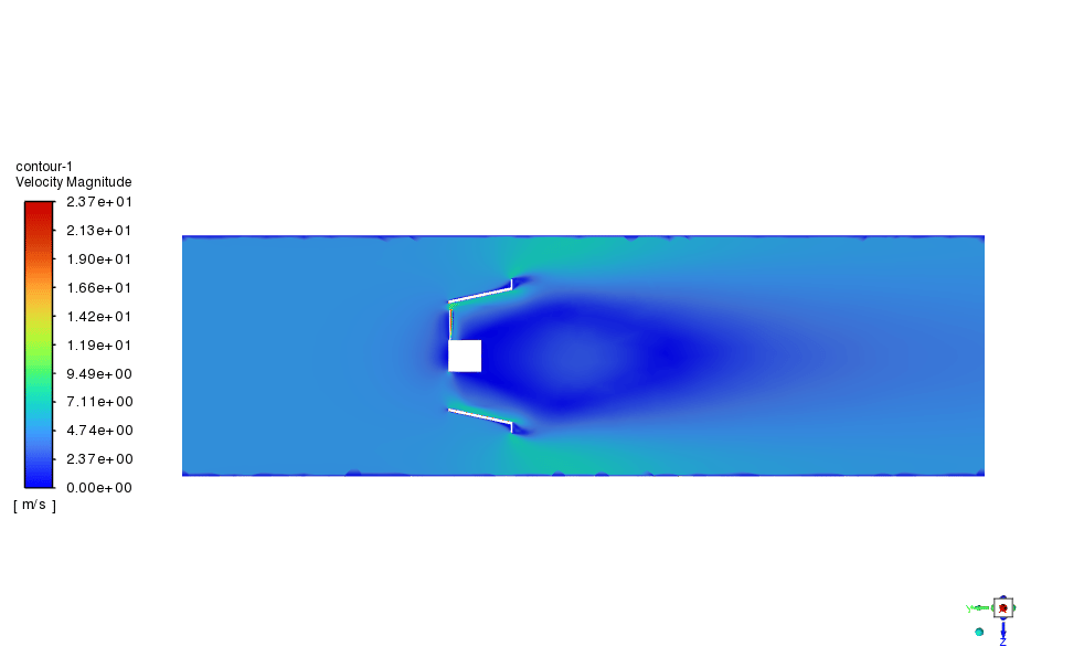
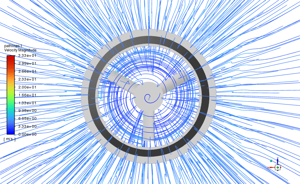
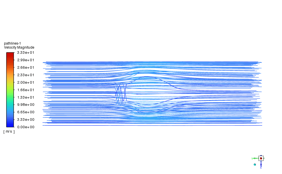
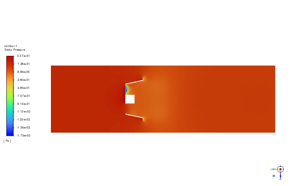
After the simulation process, 2D & 3D contours are extracted, as shown below. To assess properly, the torque generated by the turbine blade around the y-axis is reported by ANSYS Fluent. The results show a significant increase in torque which equals 63%! or in other words, the performance of wind turbines. To conclude, in tip-speed-ratio of 2.5 is a great effect but should be observed for different working conditions.
| Without Duct | With Duct | |
| Wind Turbine Torque [N.m] | 0.0031304626 | 0.0051037854 |


Zita Runte Sr. –
The training material is incredibly detailed and comprehensive. It really helps to illustrate the benefits that duct installation has on the overall performance and efficiency of the HAWT system.
MR CFD Support –
We’re delighted to hear the training was helpful and enriched your understanding of the duct impact on HAWT efficiency. Your positive feedback is greatly appreciated, thank you!
Sammie Spinka –
I am absolutely thrilled with the precision of the CFD simulation for the HAWT performance both without and with the duct. Learning the impact of the duct on torque efficiency, more notably the substantial 63% increase, was an eye-opener. Great job on illustrating complex fluid dynamics concepts so clearly!
MR CFD Support –
We are thrilled to hear you found the simulation insightful and that it effectively demonstrated the effects of duct implementation on the performance of the HAWT! Thank you for your positive feedback; it motivates us to continue providing comprehensive and detailed CFD products.
Prof. Kamron Bednar MD –
I’m very impressed with the CFD simulation comparing HAWT performance with and without a duct. It’s exciting to see a 63% increase in torque using a duct. The detailed approach in setting up the simulation shows MR CFD’s thorough understanding of both HAWT systems and CFD analysis.
MR CFD Support –
We appreciate your positive feedback! Ensuring a rigorous and detailed approach to our simulations is part of our commitment to providing high-quality learning experiences. It’s exciting to share the impact such modifications can have on enhancing turbine performance. Thank you for your recognition, and we’re delighted that you found the simulation valuable.
Mr. Wilson Corwin III –
The simulations demonstrate a noteworthy increment in torque upon using a duct. Does the use of a duct affect the longevity or maintenance requirements of the HAWT in any way? Should this be a consideration for actual implementation?
MR CFD Support –
In the simulations, elements such as longevity and maintenance are not directly modeled; however, intuitively, adding a duct could influence the structural loading and potential wear points of a horizontal-axis wind turbine. Any actual implementation should indeed consider impacts on maintenance and durability along with aerodynamic performance improvements.
Madeline Cremin –
This CFD training for the HAWT duct effect is amazing! Seeing a 63% increase in torque with the duct implementation is impressive. Great to know that the effect of ducted turbines can be simulated accurately using ANSYS Fluent.
MR CFD Support –
We appreciate your positive feedback on the HAWT duct effect CFD training. It’s wonderful to hear that our products are helping customers understand the impact of design modifications like duct implementation on wind turbine performance. Thank you for choosing MR CFD for your simulation needs!
Krystina Aufderhar –
I was fascinated by how much the duct improved the HAWT performance! Great findings!
MR CFD Support –
Thank you for your kind words! We’re thrilled to hear that you found the improvement in the HAWT’s performance due to the duct insightful. It’s fascinating to see the impact of engineering modifications on renewable energy technology. Your feedback is greatly appreciated!
Alice Muller –
I just finished learning from the ‘Duct Effect on HAWT Performance, CFD Simulation ANSYS Fluent Training’, and I must say, the results are astonishing! A 63% increase in torque because of a duct is quite impressive. Clear, detailed instructions made the CFD analysis intriguing and understandable. Complex concepts such as the multi-reference frame and polyhedron elements meshing are expertly broken down. Highly recommend it to anyone looking to understand wind turbine performance optimization!
MR CFD Support –
We’re thrilled to hear that you found the ‘Duct Effect on HAWT Performance, CFD Simulation ANSYS Fluent Training’ so informative and beneficial! It’s fantastic to learn that our efforts to deliver clear and detailed academic material are appreciated by our keen customers like you. We greatly value your recommendation, and we hope you continue to enjoy our training products. Thank you for choosing MR CFD Company for your learning journey.
Frida Moore –
The CFD simulation course improved my understanding of the impact of ducts on HAWT performance. The detailed comparison clearly outlined the benefits. Will the course be updated with simulations at different tip-speed ratios to observe effects under varying conditions?
MR CFD Support –
Thank you for your interest in the Duct Effect on HAWT Performance course. We’re glad to hear the course benefited you. Currently, the simulations focus on a tip-speed ratio of 2.5. Updates on additional simulations at different tip-speed ratios are planned for the future to provide a comprehensive understanding of the performance in various conditions. We will notify our users when these updates are available.
Alvera Hane Sr. –
The transformative effects of using a duct on HAWT performance seen in these results are remarkable. It’s interesting to see how significant improvements can be made to existing technologies by altering certain aspects such as incorporating a duct. This detailed review really helps visualize the effects on performance metrics like torque.
MR CFD Support –
Thank you for the kind words and for your interest in our CFD simulation training. We’re thrilled to hear that you found our case study on the Duct Effect on HAWT Performance insightful, and that you’re appreciative of the level of detail providing demonstrable improvements in turbine performance. We continue to strive for comprehensive and practical engineering simulations that offer valuable insights to our customers.
Emmalee Haley Jr. –
The clarity on the significance of ducts in enhancing wind turbine performance was especially well-presented. The numerical data on torque improvement was compelling!
MR CFD Support –
Thank you for your kind feedback! We are delighted to hear that you found the simulation results and the increase in torque evidence due to the duct effect informative and clear. If you need further insights or have more questions, feel free to reach out!
Josianne Bashirian –
The simulation results showing a 63% increase in torque with the duct are impressive. Love seeing such a detailed explanation of the methodology and the simulation setup!
MR CFD Support –
We’re thrilled to hear that you find the results and explanations impressive. It’s rewarding to know our efforts to provide comprehensive training material are appreciated. Thank you for your positive feedback!
Dr. Kaden Gutkowski –
I’ve completed the boundary layer study following your steps in the Duct Effect on HAWT Performance tutorial. Could you clarify if additional y-plus calculations for wall treatment are needed in similar models? How critical are such calculations for precision in CFD simulations involving turbines?
MR CFD Support –
In CFD simulations that involve the behavior of flow around aerodynamic surfaces like turbine blades, calculating the y-plus value is crucial for capturing the effects of near-wall turbulence accurately. The y-plus value is used to determine the appropriate wall treatment—whether a wall-function approach or a low-Reynolds-number approach is more suitable. Such calculations are therefore fundamental for precision, affecting how well the cfd model captures the flow physics, especially in the boundary layer. For a HAWT performance study as significant as the one you’ve completed, ensuring that y-plus values align with recommended practices is essential to achieve results with a high degree of confidence.
Ms. Juana Feil –
Really loved how detailed and educational this CFD simulation on HAWT performance was! Saw clear benefits of using a duct just by comparing the torque values. Wonderful course format and clarity.
MR CFD Support –
Thank you so much for your positive feedback on our HAWT performance CFD simulation training. We are thrilled to hear that you found it detailed and educational, and that the torque comparison effectively illustrated the benefits of using a duct. Your compliments are greatly appreciated, and we look forward to providing you with more valuable learning experiences.
Prof. Roderick Rosenbaum –
The comprehensive nature and clear explanations in this CFD simulation training course made understanding the complex interaction between duct design and HAWT performance seem like a breeze. The meticulous use of meshing and the detailed outline of the computational setup, along with the MRF model, provided thorough insight—leading me to a solid understanding of how placing a duct can enhance turbine torque substantially. The presentation of simulation results in multiple forms, including 2D and 3D contours, made interpretation of the data easy and accessible, which is greatly appreciated!
MR CFD Support –
Thank you for your positive feedback! We are delighted to hear that you found the training course on the duct effect on HAWT performance thorough and understandable. It’s fantastic to know that the course material, including the meshing techniques and detailed computational setup, contributed effectively to your learning experience. We’re also glad to hear that the presentation of results, with both 2D and 3D visualizations, was well-received and useful in your data interpretation process. We appreciate your detailed review and are grateful that our product could assist you in enhancing your CFD knowledge and skills.
Everardo Funk I –
I’m thrilled with the increase in performance! Can this CFD simulation be customized to different types of duct designs to see how each one affects turbine efficiency?
MR CFD Support –
Thank you for the positive feedback! Yes, the CFD simulation can be customized for various duct designs to evaluate their effects on turbine efficiency. Different geometries can be modeled and analyzed in ANSYS Fluent to determine the most effective design for performance enhancement.
Dr. Estelle Johnston IV –
I just went through the ‘Duct Effect on HAWT Performance’ simulation and was amazed to see the increase in torque of 63% with the duct. The level of detail and depth you’ve provided in the study helped me understand the significance of different design modifications on turbine performance. Great work on creating a comprehensive training module that truly enables practical learning of CFD in wind turbine applications!
MR CFD Support –
Thank you so much for your kind words! We are thrilled to hear that you found the ‘Duct Effect on HAWT Performance’ simulation informative and useful. Our team takes great pride in developing detailed and practical CFD training modules to enhance understanding in real-world applications. Your positive feedback motivates us to continue providing high-quality learning experiences. If you have any further questions or need more insights, feel free to reach out!
Deanna Thiel –
I am impressed by the substantial increase in performance of the HAWT when using the duct. This clearly shows the significance of optimizing turbine design to enhance efficiency. Great work on providing a comprehensive and easy-to-follow breakdown in the comparison between duct and no-duct scenarios in the CFD simulation.
MR CFD Support –
Thank you for your acknowledgment and the positive feedback on the duct effect study. We are pleased to hear that the results of the CFD simulation proved insightful, and the comparative analysis was helpful! If you need further information about the simulation, or if you’re interested in exploring additional variable impacts on turbine performance, please reach out to us or visit our website for more training materials.
Barrett Schaden DDS –
The course clarified the duct effect on HAWT performance brilliantly. The attention to detail in simulation setup and comparison of results with and without the duct made the concepts very tangible. I’m particularly impressed by the significant torque improvement indicated in the findings.
MR CFD Support –
Thank you so much for your positive feedback! We are thrilled to hear that you found the course both enlightening and detailed. It is rewarding to know that the comparison effectively demonstrated the duct’s influence on the HAWT’s performance. Your appreciation motivates us to continue delivering high-quality educational content for our learners. If you have any more questions or need further assistance, feel free to reach out!