
Shell and Helical Tube Heat Exchanger CFD Simulation, ANSYS Fluent Training
$80.00 Internship
- The problem numerically simulates a Shell and Helical Tube Heat Exchanger using ANSYS Fluent software.
- We design the 3-D model with the Design Modeler software.
- We mesh the model with ANSYS Meshing software, and the element number equals 1796590.
- The Energy Equation is activated to consider heat transfer.
To Order Your Project or benefit from a CFD consultation, contact our experts via email (info@mr-cfd.com), online support tab, or WhatsApp at +44 7443 197273.
There are some Free Products to check our service quality.
If you want the training video in another language instead of English, ask it via info@mr-cfd.com after you buy the product.
Description
Description
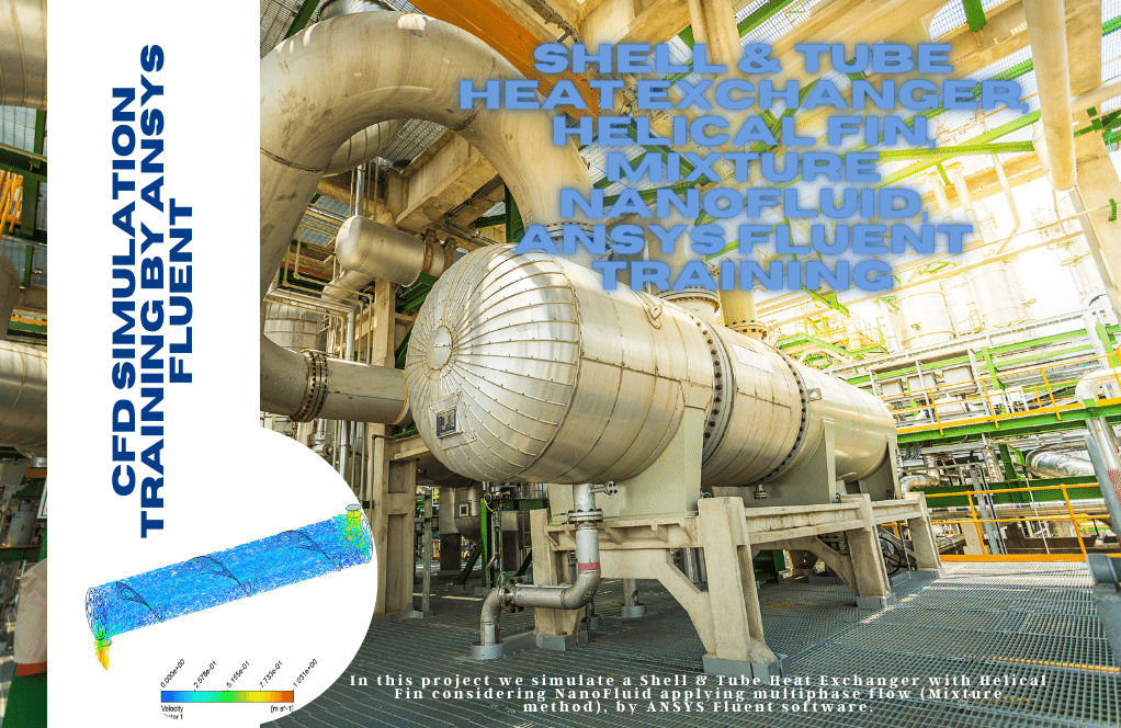
This simulation is about a shell and helical tube heat exchanger via ANSYS Fluent software.
The helical heat exchanger consists of several coils (tubes or helical tubes) with spring-like curves placed inside a cylindrical chamber called a shell. Several spirals are usually used instead of one. But many helical heat exchangers use only one helix to increase heat transfer.
The working principle of a helical heat exchanger is similar to that of a conventional shell and tube heat exchanger. The only difference between the two heat exchangers is the optimal use of space in the helical heat exchangers.
This project investigates the heat transfer between two hot and cold working fluids inside a helical heat exchanger. The hot fluid enters the computational zone with a mass flow rate of 0.05 kg/s and a temperature of 313K. The cold fluid enters the helical tubes with a mass flow rate of 0.0333 kg/s and a temperature of 289 K.
The geometry of the present model is drawn by Design Modeler software. The model is then meshed by ANSYS Meshing software. The model mesh is unstructured, and 1796590 cells have been created.
shell and helical tube Methodology
In this simulation, the energy model is activated because the main goal of this project is to investigate heat transfer in the heat exchanger. The model consists of two parts, cold and hot.
The use of a wall between these two parts is known as the heat transfer boundary. Heat transfer can be modeled using the coupled boundary condition for this wall.
shell and helical tube Conclusion
After simulation, the contours of temperature, velocity, and pressure are obtained. We can also get the temperature of the cold flow (one of the two hot and cold flows) at the outlet and inlet, equal to 308.04 K and 289 K, respectively.
Then, based on the formula, we get the value of the heat transfer rate. Now we compare this calculated value (2651.65 W) with the value obtained from the fluent calculation (2998.19 W). The percentage of comparison error is equal to 1%.
Reviews
You must be logged in to post a review.
Dr. Emil Wolf II –
I’m thrilled with how the complicated geometry of a helical heat exchanger was explained and meshed with such precision. The detailed results on temperature and velocity profiles provided clear insights into the efficiency of the heat exchanger design.
MR CFD Support –
Thank you so much for your positive feedback! We’re delighted to hear that our explanation and results were clear and helpful. It’s great to see that you found the insights into the heat exchanger’s efficiency valuable. If you have any further questions or need additional information, feel free to reach out.
Hertha Kihn –
I’m thrilled with the precision in heat transfer rate calculations! Can this setup handle variations in flow rate for different industrial applications?
MR CFD Support –
Thank you for your positive feedback! Yes, the simulation set up for the shell and helical tube heat exchanger is quite flexible and can be adjusted to cater to different flow rates as required for various industrial applications. The geometry, boundary conditions, and mesh can be adapted to achieve accurate results for differing scenarios.
Samir Lang –
I’m impressed with the results showcased in the findings. Can you tell me if this training includes tips on how to optimize the heat exchanger design for efficiency?
MR CFD Support –
Thank you for your kind words. The training focuses on simulating and analyzing heat transfer within a helical tube heat exchanger, but it also includes guidelines on evaluating performance and identifying parameters that influence efficiency. Optimization techniques may not be the main focus, but with the provided data, users can understand how design changes impact heat transfer and can extrapolate ways to improve overall efficiency.
Nolan Nader –
The detailed simulations provided by this learning product seem to be thoroughly performed and concise. Very clear step-by-step methodology enhanced my understanding of the heat transfer processes within helical tube heat exchangers. Great job!
MR CFD Support –
Thank you for your kind words on our Shell and Helical Tube Heat Exchanger CFD Simulation training! We’re thrilled to hear that our detailed methodology has significantly contributed to your understanding. If you have any more feedback or need further assistance, we’re here to help!
Mrs. Otilia Pouros –
The sheer detail in explaining the Shell and Helical Tube Heat Exchanger simulation is amazing. The step-by-step setup, the clarity on methodology, and the insightful conclusion truly helped me grasp the essentials of such a complex process. The understanding of how the energy model is crucial for heat transfer analysis is particularly well conveyed.
MR CFD Support –
Thank you for your kind words! We’re thrilled to hear that you found the explanation clear and helpful. It is our goal to ensure our users have a comprehensive understanding of the simulations we provide. If you have any more questions or need further information, don’t hesitate to ask. Happy simulating!
Eliezer Kub –
This Shell and Helical Tube Heat Exchanger simulation training has been so instructional! The visuals on temperature contours were particularly enlightening. It has definitely enhanced my understanding of the heat transfer processes within such exchangers.
MR CFD Support –
We’re thrilled to hear that our simulation training on the Shell and Helical Tube Heat Exchanger has been helpful to you! Understanding the intricacies of heat transfer in these systems is crucial, and we’re glad our visuals and explanations could make the concepts clear. Thank you for taking the time to share your positive experience.
Baron Breitenberg –
This training material seems pretty comprehensive! It’s neat to see how well the principles of heat exchange are conveyed through the helical heat exchanger model. The methodology outlined here shows the efficiency of ANSYS Fluent in solving complex CFD problems which include energy equations. I appreciate the detailed discussion on temperature, velocity, and pressure results which should help anyone understand the overall heat transfer process within such systems. It’s also impressively accurate going by the error margin in the calculated heat transfer rate!
MR CFD Support –
Thank you for your positive feedback! We’re delighted to hear that our simulation material on the shell and helical tube heat exchanger met your expectations and helped you gain a better understanding of the heat transfer principles in action. We strive to provide thorough and accurate simulation training, so we’re pleased to know the error margin and simulation results were satisfactory. If you have any more questions or need further assistance, we’re here to help.
Jazlyn Dietrich –
The simulation and results provided by MR CFD exceeded my expectations. The level of detail in both the methodology and the conclusion sections really helped me understand the process behind helical heat exchangers. I am especially impressed by how the software managed to successfully simulate the physical phenomena and yield such accurate results in terms of heat transfer rate.
MR CFD Support –
Thank you for your review! We’re thrilled to hear that the simulation results not only met but exceeded your expectations. It’s fantastic to know that the detailed explanation contributed to your understanding of helical heat exchangers. Your positive feedback is greatly appreciated, and if you have any more questions or need further assistance, don’t hesitate to reach out!
Katrine Barrows –
The training for the helical tube heat exchanger simulation was amazing! The detailed breakdown of the setup process helped me understand each step clearly.
MR CFD Support –
Thank you for your positive feedback! We are pleased that our training for the Shell and Helical Tube Heat Exchanger CFD Simulation through ANSYS Fluent was able to clearly demonstrate the setup and simulation process. We strive to make complex topics accessible and are glad you found it helpful.
Alverta O’Connell –
The details on the simulation of the shell and helical tube heat exchanger are meticulous and offer such rich insights into the methodology! It’s delightful to know ANSYS Fluent could simulate this setup efficiently and provide accurate heat transfer rate assessments. Truly intriguing work by MR CFD Company!
MR CFD Support –
We greatly appreciate your feedback and the positive review. It’s a pleasure to see our clients derive value and gain important insights from simulations such as the one done for the shell and helical tube heat exchanger. Thank you for choosing our ANSYS Fluent Training course!
Laura Crooks –
I just finished going through the Shell and Helical Tube Heat Exchanger CFD Simulation tutorial and got fantastic results. Everything was clearly explained, and the setup guide was easy to follow. My simulations are much more efficient now, and the results corroborate with theoretical expectations, which is quite satisfying! Thank you, MR CFD, for such a valuable learning experience.
MR CFD Support –
We’re delighted to hear that the tutorial on Shell and Helical Tube Heat Exchanger CFD Simulation was beneficial for you. It’s fantastic that your simulations align with theoretical predictions and that our material contributed to your learning process successfully. Thank you for your positive feedback and for choosing MR CFD Company’s learning products!
Marcus Pouros –
The simulation sounds thoroughly detailed. I’m especially interested in how the heat transfer rates from your CFD analysis compared so closely with theoretical values. The use of single versus multiple helices in the design for optimal space usage and effectiveness sounds like a critical factor in efficiency—a nice job capturing the nuanced physics in action!
MR CFD Support –
Thank you for your kind words! It’s great to hear that the detailed information and comparison of heat transfer rates provided in this simulation were interesting to you. We strive to ensure our simulations are not only accurate but also insightful by encompassing all such crucial design elements and physics. Your acknowledgment motivates us to keep delivering high-quality CFD simulations and trainings.
Neal Purdy –
Just finished the ‘Shell and Helical Tube Heat Exchanger CFD Simulation’ course by MR CFD. The detailed explanation on setting up coupled boundary conditions was incredibly helpful, and the balance between theory and practical CFD application was just right.
MR CFD Support –
Thank you for your positive feedback on our Shell and Helical Tube Heat Exchanger CFD Simulation course! We’re delighted to know that the content met your expectations and was beneficial in understanding the coupled boundary conditions. MR CFD prides itself on delivering high-quality education that balances theoretical knowledge with practical skill-building. Your success is our goal!
Saige Doyle –
The practical outcomes of this training seem impressive! It was very helpful to understand the comparison with the theoretical value, and the error margin is quite low. Plus, the visual representations of temperature and flow distributions helped me grasp the heat exchange process better.
MR CFD Support –
We deeply appreciate your acknowledgment and are glad to know the training material was effective for you. Understanding complex heat exchange systems can be challenging, but we’re pleased to see our simulation helped clarify the concept. Thank you for sharing your thoughts!
Nelda Blick Sr. –
I’m impressed with how detailed the simulation can calculate the heat transfer rate. Brilliant work on comparing the results and having such a minimal error margin too!
MR CFD Support –
Thank you for your kind words! We are thrilled to hear that our simulation’s precision and detail have met your expectations. Ensuring accuracy in our results is a top priority for us. We appreciate your recognition of the effort put into achieving a low error margin in our heat transfer rate calculations.
Mrs. Burnice Dibbert MD –
I’m extremely satisfied with the results that the Shell and Helical Tube Heat Exchanger simulation was able to achieve. The detailed explanation of the process, as well as the clear indication of the outlet temperatures and comparison error, gave me a big picture of the skill level required and the quality of training provided.
MR CFD Support –
We’re thrilled to hear about your positive experience with the Shell and Helical Tube Heat Exchanger CFD Simulation training! Thank you so much for your complimentary review. It’s always rewarding to know that our customers are benefiting from the quality education we strive to provide with ANSYS Fluent software. If there’s anything else we can do to assist you in your learning journey, please let us know.
Dawn Reichel –
I am really impressed by how thorough the analysis on the shell and helical tube heat exchanger is. It’s enlightening to see how the helical design optimizes space and enhances heat transfer. Great use of ANSYS Fluent!
MR CFD Support –
Thank you for your kind words! We are thrilled to hear that you found the simulation enlightening and appreciated the details of our analysis. Our aim is always to provide comprehensive insights using tools like ANSYS Fluent to help understand and optimize such complex engineering systems. If you have more questions or need further clarifications in the future, don’t hesitate to reach out.
Rogelio Heller –
I found the methodologies discussed and the final comparison between the calculated heat transfer rate and the one obtained from the Fluent calculation intriguing. Excellent practical demonstration of the concepts!
MR CFD Support –
Thank you for your positive review! We’re thrilled to hear that you found the simulation methodology and error comparison informative and practical. It’s great to know our training material effectively demonstrates complex engineering concepts. Your feedback is appreciated!
Prof. Rasheed Bartell –
After completing the training course, I must say I’m genuinely impressed with how comprehensive it was. The step-by-step helical heat exchanger simulation provided great insights into practical CFD applications, particularly regarding heat transfer efficiency within compact structures. Hats off to MR CFD Company for such enlightening content!
MR CFD Support –
Thank you very much for your positive feedback! We’re thrilled to hear that you found our training course on the Shell and Helical Tube Heat Exchanger to be comprehensive and enlightening. At MR CFD Company, we strive to create detailed and useful content for all our users, and we are glad you found it practical. We appreciate the time you took to write this review, and we look forward to providing you with more valuable learning experiences in the future!
Dr. Braulio Herman MD –
I’m deeply impressed by the results of this heat exchanger simulation. The detailed analysis and accurate data representations are evident in the provided material.
MR CFD Support –
Thank you for your positive feedback! It’s fantastic to hear that our simulation met your expectations with accurate and detailed analyses. We’re grateful for your appreciation of our product.
Lacey Ankunding MD –
The training was enlightening, and simulations especially helped clarify heat transfer principles. I saw an increase in my understanding of how to set up the coupled boundary conditions.
MR CFD Support –
We’re thrilled to hear that our ANSYS Fluent training on the Shell and Helical Tube Heat Exchanger was so helpful for you! It’s great to know you’ve gained a better understanding of setup and heat transfer processes. Thank you for taking the time to share your positive experience and feedback with us!
Dr. Kelton Swaniawski I –
Absolutely stellar results demonstrated by MR CFD in simulating a shell and helical tube heat exchanger. The level of detail in outlining the process, from geometry to mesh generation, reflects high standards of coursework. Additionally, practical outcomes such as the temperature variations and heat transfer rate calculations provide a profound grasp of the thermal dynamics at play. It’s this depth of analysis that truly enriches learning for students and professionals alike. Kudos to the entire team!
MR CFD Support –
Thank you for your positive feedback! We are thrilled to hear that you found our simulation and training materials to be helpful and detailed. Our team strives to provide high-quality educational resources to enhance the learning experience. Your compliments are greatly appreciated, and we look forward to continuing to serve our customers with excellence.
Laura Hodkiewicz –
After going through this CFD simulation training, I finally understood how to setup and analyze a shell and helical tube heat exchanger using ANSYS Fluent. The detailed explanation of methodology and the structured way the simulation steps are presented allowed me to easily grasp the concepts. The visualizations of temperature, velocity, and pressure were particularly helpful in understanding the flow and heat transfer. A thank you to MR CFD for creating such a comprehensive and informative training product, which has enhanced my understanding of heat exchanger simulation a great deal!
MR CFD Support –
We’re thrilled to hear that our Shell and Helical Tube Heat Exchanger CFD Simulation training has been so informative and useful to you! Thank you for your kind words. It’s always gratifying to know that our training products are making a positive impact on our customers’ learning experiences. If there are any more CFD concepts or simulations you need help with in the future, don’t hesitate to reach out or explore our other product offerings!
Chauncey Feeney –
Fantastic! Learning from this simulation made complex concepts of heat exchangers much clearer. The structured layout of temperature, velocity, and pressure analysis was especially helpful.
MR CFD Support –
Thank you for your kind words! We’re thrilled to hear that our simulation was able to clarify complex concepts for you. Your appreciation for the structured layout of our analysis encourages us to continue providing high-quality learning products. If you have any more feedback or need further assistance, feel free to reach out!
Tracey Harber V –
I was genuinely impressed with the level of detail in the simulation and how accurately the temperature differentials were captured. Great job!
MR CFD Support –
Thank you for the kind words! We strive to provide accurate and detailed simulations to help our users understand and visualize complex heat transfer processes. We’re glad to hear you found the simulating results impressive.
Diana Schoen –
I just completed the Shell and Helical Tube Heat Exchanger CFD Simulation training with ANSYS Fluent, and I’m truly impressed. The details and procedures were impressive, making complex concepts much easier to grasp. The results were very accurate, and comparing each point with theoretical expectations provided me with a strong understanding of heat exchanger operations. Thank you, MR CFD, for such a well-structured and insightful training module.
MR CFD Support –
We’re delighted to hear that you found our Shell and Helical Tube Heat Exchanger CFD Simulation training resourceful and that it enhanced your understanding of heat exchanger operations. Thank you for choosing MR CFD to enrich your knowledge and for taking the time to provide us with your positive feedback. If you have any further questions or need assistance in the future, don’t hesitate to reach out!
Kendall Nienow –
Terrific results! It’s clear that the methodology for the shell and helical tube heat exchanger was well executed, leading to nearly exact correlation between theoretical and simulation heat transfer rates. I am particularly impressed by the low error percentage. Kudos to your team for effectively using the energy model and coupled boundary condition to achieve these accurate simulations.
MR CFD Support –
Thank you for your positive feedback! We’re pleased to hear that you are impressed with the accuracy of our simulation for the shell and helical tube heat exchanger. Our team always strives to utilize the most efficient modeling techniques to ensure high-quality results. We appreciate you taking the time to recognize our efforts.
Germaine Orn –
I’m impressed with how the simulation handles the helical design of the heat exchanger to effectively use the space and increase the heat transfer. Great job on achieving precise results between the calculated and Fluent calculated heat transfer rates!
MR CFD Support –
Thank you for your kind words and for noticing the attention to detail in our simulation! We strive for accuracy and precision in our work and it’s rewarding to see that it resonates with our users. Your recognition of the meticulous design and the effective use of space in the helical heat exchanger is much appreciated. Thank you once again for choosing our training products, and we look forward to providing you with more high-quality simulations.
Rosalee Champlin –
I’m very satisfied with how detailed the simulation was and the accuracy of the heat transfer rate calculations. Understanding heat transfer in helical heat exchangers has never been clearer—great job MR CFD Company!
MR CFD Support –
We’re thrilled to hear that you’ve had such a positive experience with our Shell and Helical Tube Heat Exchanger CFD Simulation training! Our team strives to provide comprehensive and accurate simulations to facilitate a deeper understanding of heat transfer processes. Thank you for choosing MR CFD Company, and we appreciate your kind words!
Rex Wiegand PhD –
Fantastic learning tool for visualizing and understanding heat exchange in a helical design! The intricacy of the coil within the ANSYS simulation provided clear insights into temperature and velocity gradients. Seeing both the practical setup and the computed results gave a great comprehensive picture of the principles at work.
MR CFD Support –
Thank you for your positive feedback! We’re delighted to hear that our simulation has provided you with a clear understanding of the heat exchange process in a helical tube heat exchanger. It’s gratifying to know that the level of detail in the simulation was helpful for your learning. If you have any further questions or need assistance, feel free to reach out!