Packed Bed CFD Simulation by ANSYS Fluent, Training
$100.00 Student Discount
In this project, which has been done by the CFD simulation method with the help of Ansys Fluent software, and the results of this simulation have been analyzed.
Click on Add To Cart and obtain the Geometry file, Mesh file, and a Comprehensive ANSYS Fluent Training Video.To Order Your Project or benefit from a CFD consultation, contact our experts via email ([email protected]), online support tab, or WhatsApp at +44 7443 197273.
There are some Free Products to check our service quality.
If you want the training video in another language instead of English, ask it via [email protected] after you buy the product.
Description
Packed Bed Project Description
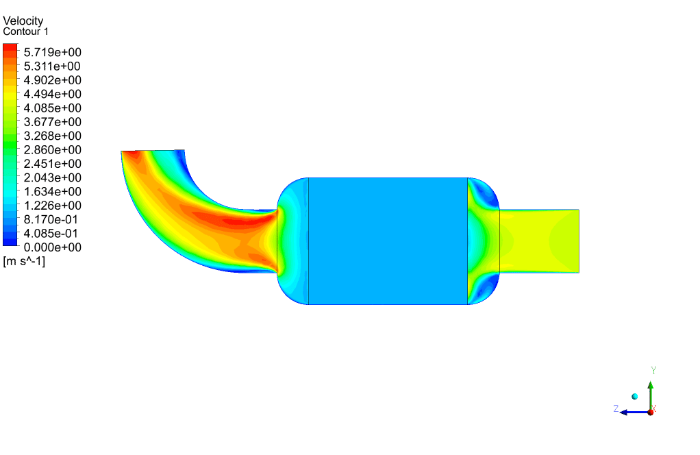
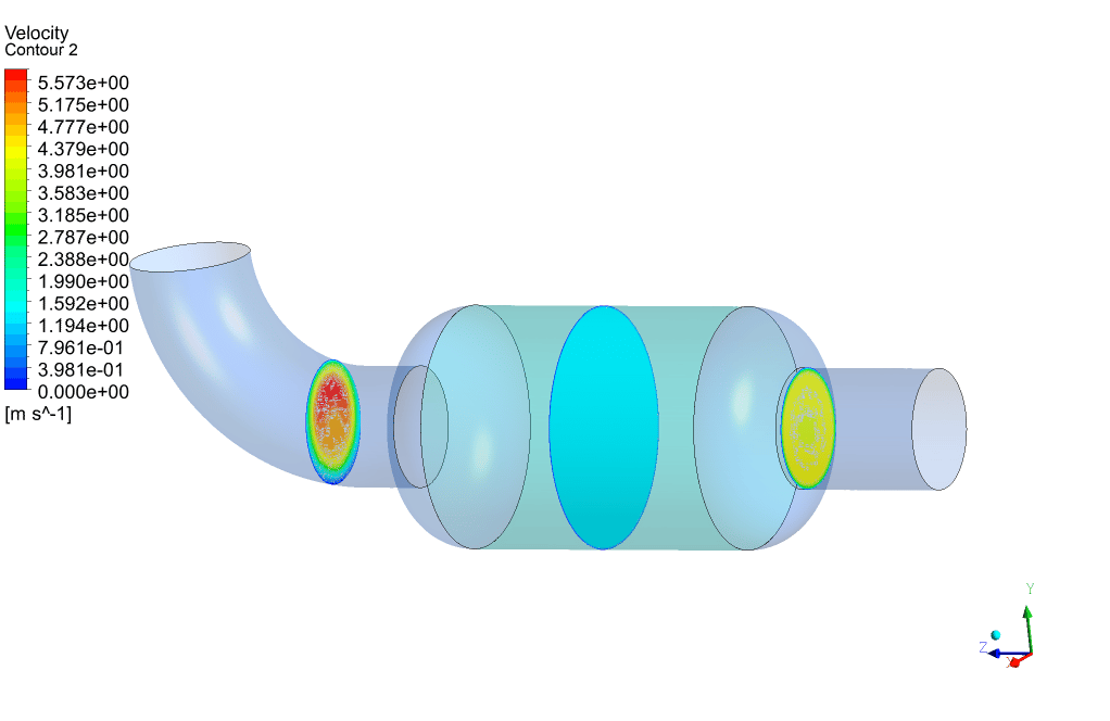
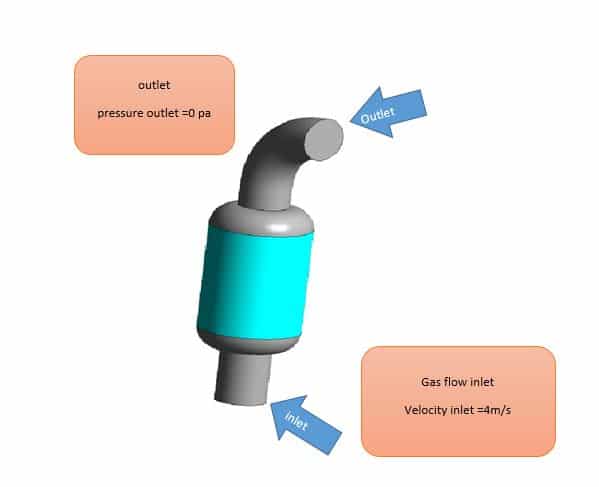
In this project, which has been done by the CFD simulation method with the help of Ansys Fluent software, the gas flow passing through the packed bed is simulated. The gas used is argon monoatomic gas, which enters at a speed of 4 m/s and for the outlet is defined zero Pascal gauge pressure. The packed bed area is a porous medium with an inertial resistance of 45 (1 / m) and viscous resistance of 3e9 (1 /m^2).
Geometry & Mesh
The three-dimensional geometry of this project has been produced with SpaceClaim software.
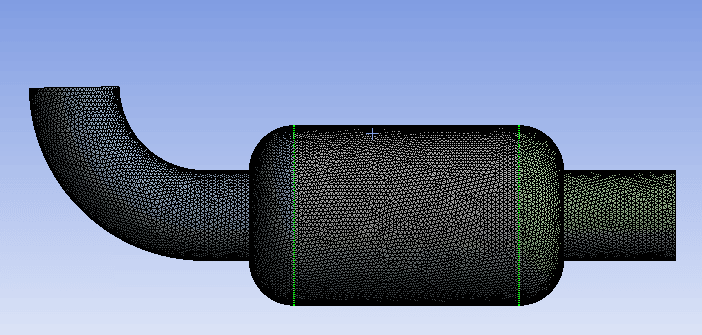
The length of the commutating domain is 80 mm, the width is 97 mm, and its height is 388 mm. meshing of this project has been done with Ansys Meshing software, and the type of elements is unstructured. Also, the total number of elements is 501444.
CFD Simulation
- the pressure-based solver method has been selected.
- The simulation is steady.
- The gravity effect is ignored.
The following tables represent a summary of the defining steps of the problem in this project and its solution:
| Models | ||
| Viscous model | k-epsilon | |
| Model | standard | |
| Cell zone conditions | ||
| Packed bed | Porous zone | on |
| Inertial resistance | 45 (1/m) | |
| Viscous resistance | 3e9 (1/m) | |
| Laminar zone | on | |
| Boundary conditions | ||
| Inlet | velocity inlet | |
| Velocity magnitude | 4m/s | |
| Outlet | Pressure outlet | |
| Gauge pressure | 0 pa | |
| Walls | Stationary wall | |
| Solution Methods | ||
| Pressure-velocity coupling | Coupled | |
| Spatial discretization | Pressure | Second-order |
| Momentum | second-order upwind | |
| Turbulent kinetic energy | first-order upwind | |
| Turbulent dissipation rate | first-order upwind | |
| Initialization | ||
| Initialization method | Hybrid |
Packed Bed Results
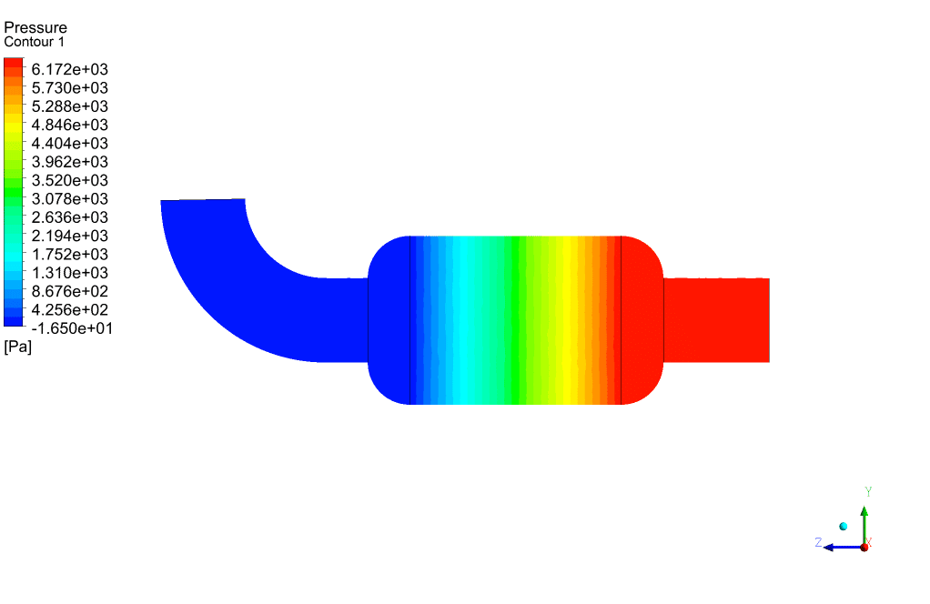
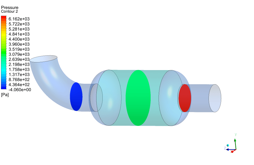
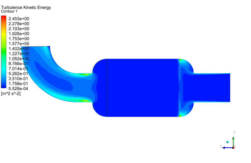
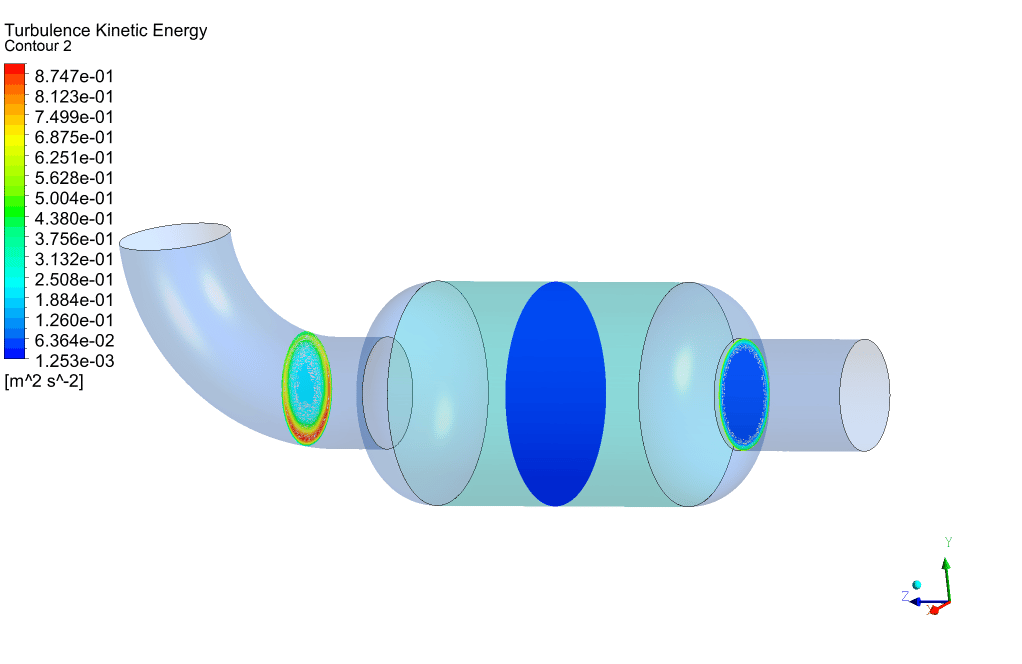
At the end of the simulation, we can see that a high-pressure drop has occurred in the porous area. The amount of pressure drop is directly related to the magnitude of the defined viscous and inertial resistances. To overcome this high-pressure drop, we must provide the pressure required to cross this barrier in the path before the gas enters the packed bed area using a pressure-boosting element such as a compressor.


Clay Fadel –
The simulation seems to encompass all the essentials of a packed bed scenario. I’m curious if there were any particular challenges or interesting findings when setting the inertial and viscous resistances for the porous medium?
MR CFD Support –
The challenges in setting inertial and viscous resistances in a porous medium like a packed bed often lie in accurately capturing the resistance encountered by the flow through the medium. These values are crucial as they directly impact the simulation results, particularly the pressure drop observed across the bed. The interesting finding here would be how closely the pressure drop predicted by the simulation matches the expected performance of an actual packed bed in real-world conditions. This validation is essential for ensuring that the simulation can be a reliable tool for designing and optimizing packed bed systems.
Abigail Cartwright –
The detailed documentation on each step of the CFD process for the packed bed project is much appreciated! The explanation regarding resistance settings for the porous medium and the results explanation is very insightful and adds to the learning experience.
MR CFD Support –
Thank you for your kind words! We’re thrilled to know that you found the project documentation and explanation clear and useful for your learning. The project was designed specifically to enhance understanding of porous media simulation, and we’re glad it has served its purpose for you. If you need any further information or assistance, feel free to reach out.
Ella Corwin –
I found the project on Packed Bed CFD simulation quite insightful. It provided a clear understanding of how to set up and run a simulation involving gas flow through a porous medium. The detail on porous media parameters was especially helpful. Great job!
MR CFD Support –
Thank you for your kind words and feedback! We are thrilled to hear that our Packed Bed CFD simulation training was informative and helpful for you. If you have any further questions or need additional assistance with CFD simulations, please don’t hesitate to reach out to us. We’re here to help!
Beverly Flatley –
After reading through the packed bed simulation training, I must say that the content provided impressive detail regarding the setup—especially the thorough explanation of resistance values applied within the porous zone. But I want to know more about post-processing. After the simulation, what kind of flow details can we visualize in the packed bed region, and how does it help in understanding the performance of the packed bed filter?
MR CFD Support –
After the completion of the packed bed simulation, post-processing tools allow for detailed visualization of several flow characteristics within the packed bed region. This includes velectionicity profiles, pressure distribution, and possibly contour plots and streamlines, providing an understanding of flow distribution, dead zones, and exhibiting the pressure drop across the packed bed more vividly. These insights are crucial in evaluating the overall performance of the packed bed, allowing for optimization of the filter media and the tweaking of operational parameters to improve effectiveness and efficiency.
Prof. Melvin Ryan –
The visualization and explanations in the training materials were very helpful! I have a clearer understanding of how different resistances in the packed bed affect the flow of argon gas.
MR CFD Support –
We’re thrilled to hear that our training materials have contributed to your understanding of CFD simulations for packed beds. Thank you for your positive feedback!
Mina Rogahn –
I was amazed by the level of detail in the simulation results. It’s clear that the CFD approach for modeling the gas flow dynamics in a packed bed using ANSYS Fluent is quite in depth and presumably accurate.
MR CFD Support –
Thank you for your positive feedback on our Packed Bed CFD Simulation training! We always strive to provide comprehensive and detailed simulations to ensure the best learning experience. We are glad to hear that you are satisfied with the quality of our training.
Prof. Ila Muller –
I’m truly fascinated by the level of detail in this training simulation for understanding the flow through a packed bed system. The step-by-step breakdown provided in the description was helpful and engaging!
MR CFD Support –
Thank you for your positive feedback! We’re delighted to hear that the detailed explanation of the simulation process for the Packed Bed CFD project has enhanced your learning experience. If there’s anything more you’d like to learn or inquire regarding our simulations or any other CFD-related training materials, please don’t hesitate to ask.