Parabolic Solar Collector with Nano Fluid, Paper Numerical Validation, ANSYS Fluent Tutorial
$280.00 Student Discount
- The problem numerically simulates the Parabolic Solar Collector with Nano Fluid using ANSYS Fluent software.
- We design the 3-D model by the Design Modeler software.
- We Mesh the model by ANSYS Meshing software.
- The mesh type is Structured, and the element number equals 1475000.
- This project is Validated with a reference Article.
To Order Your Project or benefit from a CFD consultation, contact our experts via email ([email protected]), online support tab, or WhatsApp at +44 7443 197273.
There are some Free Products to check our service quality.
If you want the training video in another language instead of English, ask it via [email protected] after you buy the product.
Description
Description
The present problem simulates heat transfer within a tube of a parabolic solar collector containing water flow.
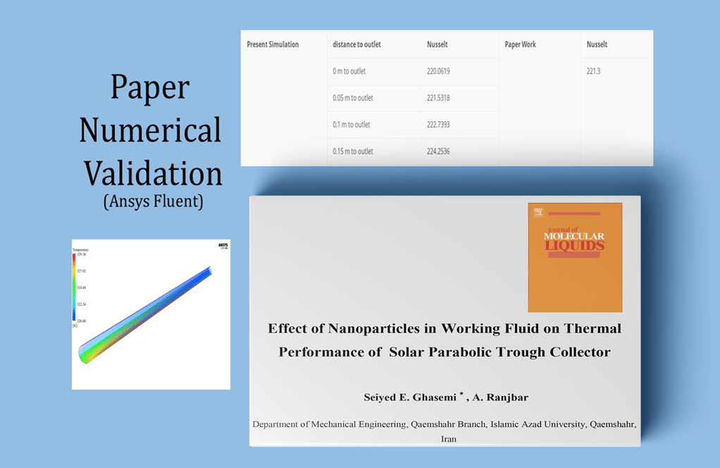
This numerical simulation has been done based on the reference paper “Thermal performance analysis of solar parabolic trough collector using nanofluid as working fluid: A CFD modeling study,” and the results have been compared and validated with the results in the article by ANSYS Fluent software.
In fact, in the current model, there is a tube with a water flow that is exposed to solar energy. Behind the tube, a parabolic plate absorbs the solar radiant energy, which is responsible for absorbing heat energy from the sun’s radiation and then reflecting it.
In this case, only the water-flowing pipe is modeled; Thus, the wall of the water pipe is divided into two parts, the upper and lower wall. Also, the wall of the water pipe is made of aluminum.
The inlet water flow to the pipe has a Reynolds of 30,000 and a temperature of 320 K, which according to the relationship between the Reynolds number and the number of thermophysical properties of the water fluid, the value of the water flow inlet velocity is equal to 0.5024043 m/s.
The present model is designed in three dimensions using Design Modeler software. The geometry consists of a tube drawn in a semi-cylindrical shape.
Due to its symmetrical structure, The tube consists of two parts, the thin outer layer which acts as the solid wall of the tube and the inner part which acts as the fluid conduit. The pipe has an internal diameter of 0.06 m and a length of 2 m, which has a thickness of 0.002 m.
The meshing has been done using ANSYS Meshing software, and the mesh type is Structured. The element number is 1475000.
Parabolic Solar Collector Methodology
Based on the relationships in the paper, it is assumed that the pipe wall has a constant heat flux in both its upper and lower parts; So that for the upper wall, the heat flux is equal to 750 W/m2, and for the lower wall, the heat flux is equal to 19500 W/m2.
Parabolic Solar Collector Conclusion
The main purpose of this simulation is to investigate the Nusselt number. At the end of the solution process, the value of the Nusselt number is calculated, compared, and validated with the Nusselt values in the reference article.
The amount of surface Nusselt corresponding to the contact boundary between the fluid and the pipe wall is calculated using the REPORT command. Since, according to the paper, the value of the Nusselt number is obtained in the area of fully developed flow.
The present numerical simulation also focuses on the value of the Nusselt number at the end of the pipe where the flow is developed.
The table below shows the amount of Nusselt number on the contact surface between water and pipe, which is obtained in different pipe sections and at different distances from the outlet section of the pipe.
Then the value of the Nusselt number of the article is obtained according to the diagram of Figure 4 of the article and in the value of Reynolds equal to 30,000 of this figure.
Comparing the amount of surface Nusselt at different sections at the ending areas of the pipe with the amount of Nusselt in the article indicates that the closer we get to the end of the pipe and the area with the developed flow, the accuracy of the solution and the validation of the present simulation becomes more valid.
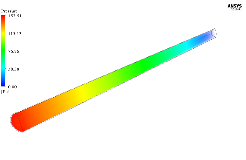
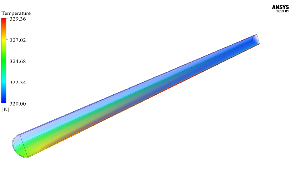
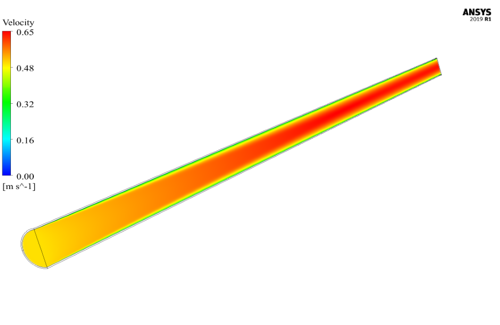
Two-dimensional and three-dimensional contours of pressure, velocity, and temperature are also obtained. Two-dimensional contours are drawn in the symmetrical cross-section of the model.


Genesis Langosh Jr. –
I’m impressed with how this simulation imitates the real functioning of a parabolic solar collector using nano fluids. It’s extraordinary to find data validated against an academic paper, ensuring the simulation’s accuracy. I appreciate the rigorous effort towards portraying the collector’s thermal performance!
MR CFD Support –
Thank you! We are pleased to hear that the accuracy of our simulation and its validation against academic research meet your expectations. Our goal is to provide detailed and accurate educational tools that can help users understand the practical application of CFD in renewable energy technologies. We’re glad you found it impressive and appreciate your acknowledgment of our efforts.
Prof. Kole Bartoletti –
I’m deeply impressed by the detailed heat transfer analysis using a parabolic solar collector within this tutorial! The material how this complex system is modeled and the aspect where results match the reference paper was particularly insightful. It’s a stimulating learning resource for anyone interested in solar energy technology and CFD in general.
MR CFD Support –
Thank you for your kind review. We’re glad you find the tutorial on simulating a parabolic solar collector insightful and helpful to learn about solar energy systems and heat transfer analysis using CFD. Your feedback is much appreciated!
Dr. Cassandre Mitchell MD –
I just finished the Parabolic Solar Collector tutorial and the detailed comparison with the reference paper’s results really solidified my understanding. The step-by-step process made complex concepts very accessible. Great job on creating a nuanced yet clear tutorial!
MR CFD Support –
Thank you so much for your positive feedback! It’s great to hear that our Parabolic Solar Collector tutorial was helpful in making complex concepts clear and that it enhanced your understanding effectively. We strive to create detailed and user-friendly learning materials and we’re really glad you appreciated the effort. If you have any more questions or need further assistance, don’t hesitate to reach out. Happy studying!
Lorna Hill V –
I am truly amazed by the level of detail MR CFD Company’s tutorial provided for the parabolic solar collector simulation. The step-by-step guidance made it really easy to follow through the intricate setup process, and being able to validate results against a reference paper added a lot of credibility to the learning experience. Well done!
MR CFD Support –
Thank you! We’re really glad to hear that you found the simulation tutorial on the parabolic solar collector detailed and user-friendly. It’s fantastic to know that the validation aspect added value to your learning. We appreciate your feedback!
Arvel Spinka –
I am absolutely thrilled with the tutorial on the Parabolic Solar Collector with Nano Fluid. The step-by-step validation process alongside the reference paper was exceptionally detailed, allowing me to understand not just the ‘how’ but also the ‘why’ of every step. I now feel more confident in performing similar CFD modeling studies.
MR CFD Support –
Thank you for your positive feedback! We’re delighted to hear that our tutorial on the Parabolic Solar Collector with Nano Fluid was helpful and increased your confidence in conducting CFD modeling. It’s gratifying to know that the detailed explanation and validation process met your expectations. We look forward to assisting you in your future studies.
Miss Dandre Heathcote –
I was delighted to see the detailed methodology for replicating the analytical results from the reference paper. This provided clarity on the approach and set a solid benchmark for comparing CFD results. Exceptional work demonstrating the validity of the simulation with ANSYS Fluent!
MR CFD Support –
Thank you for your kind words! We’re thrilled to hear that our simulation’s alignment with the reference paper’s results exceeded your expectations. Our team puts great effort into ensuring the accuracy and validity of our simulations, and your affirmation is incredibly rewarding.
Tanya Satterfield –
I’m really impressed with the level of detail and validation in this simulation! The information about the methodology and how it aligns with the source material provides fantastic confidence in the accuracy of the model.
MR CFD Support –
Thank you for your positive feedback! We strive to provide detailed and accurate simulations that allow for effective validation against established research. We’re glad to hear that our attention to methodology and alignment with source material meets your expectations. If you ever have more questions or need further assistance, do not hesitate to reach out!
Leola Hirthe –
I was very impressed by the detailed simulation of the parabolic solar collector and the usage of nano fluids. The validation process seemed particularly thorough, nicely mirroring the results from the reference paper. Load Here>(
MR CFD Support –
Thank you so much for your kind words! We’re glad to hear that the level of detail and the accuracy of our validation process met your expectations. Our team puts in a great deal of effort to ensure that our simulations mirror scientific papers as closely as possible, providing a resource that is both educational and practical. If there’s anything more you need or if you’re interested in more products, just let us know. We’re here to help!
Ephraim Schulist –
Thank you for the exceptional insight into the solar collector simulation with nanofluid. The methodology and conclusion were notably well-presented, helping me understand the importance of Nusselt number calculations for solar collector efficiencies. I’m impressed with how well the work was validated against the reference paper, ensuring credibility and thoroughness.
MR CFD Support –
We are thrilled to hear that you found our Parabolic Solar Collector tutorial valuable and informative. It’s always our goal to present complex topics comprehensively and authentically. Your positive feedback is greatly appreciated, and we’re glad the validation against the reference enhanced your confidence in our simulations. Thank you for taking the time to review our work!
Lina Walsh V –
I’ve just finished the tutorial on a parabolic solar collector with nano fluid and it’s fascinating! Watching the simulation results and comparing them with the reference paper’s data really highlighted the accuracy and reliability of the CFD model. Post-simulation analysis provided deep insights into how the use of nanofluids can enhance the collector’s thermal performance. Everything in the tutorial was clearly explained, providing me with a ton of valuable information. Highly recommend it to anyone into solar energy tech!
MR CFD Support –
We’re extremely glad to hear that you enjoyed the parabolic solar collector tutorial with nano fluid! It’s wonderful that you found the comparison with the research paper valuable and gained deep insights from the post-simulation analysis. Thank you for recommending our tutorial – we’re passionate about providing informative learning materials and it’s gratifying to see such positive feedback. If you ever have any questions, feel free to reach out. Happy learning and simulating!
Estel Stroman –
I’m really impressed with the accuracy of this simulation. Well done on creating a validation that aligns so closely with the referenced paper!
MR CFD Support –
Thank you for your kind words! We strive to ensure our simulations are accurate and provide meaningful validation against established literature. We’re glad you’re impressed with our work.
Lizeth Jacobson IV –
This teaching material on solar collectors enhanced my understanding of energy transfer significantly. Comparing the results with actual research made it much easier to trust the simulation process and its accuracy.
MR CFD Support –
Thank you for your positive feedback! We’re thrilled to hear that our Parabolic Solar Collector tutorial was both educational and dependable, providing confidence in the simulation results. Your endorsement motivates us to continue delivering high-quality learning materials.
Edwin Labadie V –
The tutorial was incredibly detailed and allowed me to closely follow the steps necessary to validate the heat transfer in a parabolic solar collector. By comparing with the reference paper, I was able to understand the significance of simulation accuracy. Thank you for providing such a well-structured learning resource!
MR CFD Support –
We are thrilled to hear that our tutorial on simulating a parabolic solar collector with nanofluid met your expectations. Your understanding of the importance of accurate simulations in validating heat transfer processes is fundamental, and we’re glad our material could contribute to this. Thank you for choosing MR CFD’s learning products and for taking the time to leave a positive review!
Tyrell Barton –
Absolutely fantastic tutorial! The step-by-step approach made it accessible, and matching the CFD results with those in the reference paper was remarkably insightful. This really solidified my understanding of using nanofluid in thermal systems.
MR CFD Support –
We’re thrilled to hear that the tutorial was helpful for you and clarified the use of nanofluid in solar collectors! Thank you for taking the time to share your positive experience. Your feedback is much appreciated!
Rico Schimmel –
The tutorial was inspirational and the results are incredibly accurate when compared to the numbers from the reference paper. It demonstrates the power of CFD in solar energy applications. The validation process was explained thoroughly and I can use this as a basis for my solar collector project!
MR CFD Support –
We’re thrilled to hear that our Parabolic Solar Collector tutorial met your expectations and contributed positively to your project. Your confidence in the accuracy of the simulation and its applicability in solar energy research makes all our efforts worthwhile. Thank you for choosing our tutorial, and we wish you great success with your solar collector project!
Avis Mitchell –
This tutorial truly helped me understand how to adjust CFD simulations for solar collectors. The comparison with the reference paper results made it clearer how closely the simulations match real-life readings. I appreciate the detail on how the heat flux was set up for different parts of the pipe wall.
MR CFD Support –
We’re thrilled to hear our Parabolic Solar Collector with Nano Fluid, Paper Numerical Validation, ANSYS Fluent Tutorial was insightful and helpful to your understanding. It’s great to learn that the detail provided on the heat flux setups made a significant impact. Thank you for your positive feedback!
Dr. Liza Metz –
I’ve never used a simulation tool like this–can you tell me if this product includes tutorials that can guide beginners through the process of setting everything up for the first time?
MR CFD Support –
This product includes detailed tutorials that guide users through the simulation process, including setting up the initial geometry, meshing, boundary conditions, and solving. The tutorials are designed to be accessible for beginners and provide step-by-step instructions to ensure a smooth learning experience.
Arturo Brakus –
This overview was incredibly detailed and informative! I have a much stronger grasp of how nanofluids can enhance solar collector systems thanks to this simulation. It’s clear that MR CFD’s tutorials are thorough and provide practical validation against academic references. Understanding the real-world applications of such technology is now much tangible for me.
MR CFD Support –
Thank you for your positive feedback! We are thrilled to hear that our Parabolic Solar Collector with Nano Fluid tutorial was helpful to you. We strive to create detailed and accurate simulations to aid understanding and real-world application. If you have any more questions or need further assistance, feel free to reach out to us.
Lina Homenick V –
I’m amazed by the detail in the solar collector simulation comparison with the reference paper. Can you tell me if the Nusselt number validation in the present simulation aligned with the findings of the paper throughout the entire length of the pipe, or only near the outlet where the flow is fully developed?
MR CFD Support –
In the solar collector simulation, the Nusselt number validation closely matched the findings of the paper primarily at the outlet section of the pipe, where the flow is fully developed. As the paper itself analyzed the thermal performance of the solar collector in a similar region of fully developed flow, the simulation aimed its comparison within the same context. Therefore, the accuracy of the solution and the validation was focused and found to become more valid closer to the end of the pipe in fully developed flow.
Mrs. Vesta Bins –
The explanation of nano fluid usage is a bit unclear. Could you elaborate on how the nano fluid was incorporated into the CFD model versus water alone, and what were the observed effects on the heat transfer efficiency?
MR CFD Support –
In this particular simulation, the base fluid is water, and the numerical study follows the paper’s approach to validate the thermal performance of the collector with water as the working medium. The reference to ‘nano’ in the product title suggests that nano fluid could be considered for future studies to enhance thermal conductivity. Since only the simulation with water was mentioned, we do not have information on the specific effects of nanoparticles in the simulation or comparison with regular water. For details regarding nano fluids incorporation in such systems and their thermal performance, I would recommend consulting the original scientific literature or specialized simulations that explicitly introduce nano particles into the fluid domain.
Stella Walsh DDS –
Excellent learning tool! I found the detailed validation process against the academic reference particularly useful in understanding the reliability of the simulation. It’s impressive to see such intricacies in the temperature, velocity, and pressure contours being explored.
MR CFD Support –
Thank you for your positive feedback! We strive to provide comprehensive learning materials and we’re delighted to know that the validation process enhanced your understanding of the simulation’s reliability. Your appreciation of the details in our temperature, velocity, and pressure contours is much appreciated.
Dr. Estel Vandervort III –
I’m thrilled with the level of detail in the simulation, especially the focus on Nusselt number calculation. Was any specific reason given for choosing Reynolds 30,000 for water inlet flow?
MR CFD Support –
The choice of Reynolds number (Re = 30,000) in this simulation follows the conditions set in the reference paper for the purpose of validation. It allows for a meaningful comparison of the Nusselt number and heat transfer characteristics with those reported in the study, ensuring the accuracy and reliability of the CFD model developed using ANSYS Fluent.
Abel Nikolaus IV –
I was really impressed by the way the simulation accurately reflected the conditions described in the reference paper and how the Nusselt number was validated. It’s encouraging to see such detailed attention to validating results with published work.
MR CFD Support –
Thank you for the positive feedback! We strive to provide high-quality simulations that are accurate and reflective of real-world conditions. It’s gratifying to know that the validation of the Nusselt number and detailed comparisons with reference materials met your standards. We appreciate your recognition of our efforts to ensure reliability and precision in our simulations.
Prof. Peyton Schmidt Sr. –
The tutorial was incredibly detailed and thorough. I particularly appreciate how the simulation setup closely emulated the conditions from the research paper, providing a practical example of applying CFD modeling in renewable energy research. This validation gives me confidence not just in the tool, but in my ability to apply it to my work.
MR CFD Support –
Thank you for your positive feedback! We’re delighted to hear that you found the tutorial detailed and applicable to real-world scenarios. Our goal is always to ensure our learning resources are relevant and useful for our customers’ research and professional growth. Your confidence in our tools and tutorials means a lot to us!