
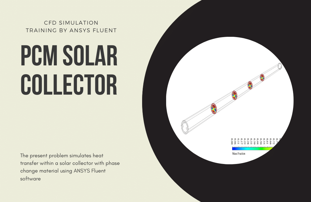
PCM in Glass-Coated Circular Chamber CFD Simulation
$100.00 Internship
- The problem numerically simulates Phase Change Material in Glass-Coated Circular Chamber using ANSYS Fluent software.
- We design the 2-D model by the Design Modeler software.
- We Mesh the model by ANSYS Meshing software, and the element number equals 4797.
- We perform this simulation as unsteady (Transient).
- We use the Solidification and Melting model to define phase change materials.
To Order Your Project or benefit from a CFD consultation, contact our experts via email (info@mr-cfd.com), online support tab, or WhatsApp at +44 7443 197273.
There are some Free Products to check our service quality.
If you want the training video in another language instead of English, ask it via info@mr-cfd.com after you buy the product.
Description
Phase Change Material in Glass-Coated Circular Chamber, ANSYS Fluent CFD Simulation Tutorial
The present problem simulates the performance of PCM in Glass-Coated Circular Chamber by ANSYS Fluent software. We perform this CFD project and investigate it by CFD analysis.
This PCM is evenly distributed inside the chamber. PCMs are materials with inorganic or organic compounds that are capable of absorbing and storing large amounts of latent thermal energy.
Thermal energy storage in these materials is achieved during the phase change process (solid phase to liquid or vice versa); So that when the phase changes from solid to liquid, they absorb heat from the environment, and when the phase changes from liquid to solid, they return the heat to the environment.
These phase-change materials have different melting or freezing temperatures.
Therefore PCM is used in heating and cooling systems; For example, these materials receive ambient heat on a hot day in the form of latent heat and melt, and then, in the cool air of the night, return the heat to the environment again, by changing the phase and solidification process.
For the present modeling, a glass coating around the chamber containing phase change material with a constant temperature of 338.15 K has been used, which is responsible for transferring heat to the phase change material.
The 2-D geometry of the model is designed using Design Modeler software. The present model includes a circle with an outer radius of 0.0335 m and an inner radius of 0.032 m. The meshing has been done using ANSYS Meshing software, and the mesh type is unstructured. The element number is 4797.
CFD Methodology
Since the nature of the PCMs of the present model is based on the phase change between solid and liquid phases, the solidification and melting model has been used for the simulation. This PCM is in the initial state of the simulation at 332.15 K.
To use the solidification and melting model, the maximum temperature at which only the solid phase exists (T_solidus), the minimum temperature at which only the liquid phase exists (T_liquidus), and the latent heat of solvent melting in the pure state (Pure solvent melting) must be used.
Because the simulation process is transient, the simulation process is performed in a time interval of 250 minutes (15,000 seconds) with a time step of 600 s.
Phase Change Material Conclusion
At the end of the solution process, liquid mass fraction and temperature contours were obtained at different times with intervals of 40 minutes.
Also, a graph of changes in the amount of liquid mass fraction over time is obtained. As it is obvious, the liquid mass fraction increases in terms of time, and the solid mass fraction decreases consequently
1 review for PCM in Glass-Coated Circular Chamber CFD Simulation
You must be logged in to post a review.
Mr. Jairo Schimmel Jr. –
This simulation is a fantastic tool for understanding the complex heat transfer phenomena in PCMs!
Miss Amaya Fahey Sr. –
Can this simulation be customized to model the phase change process in different types of PCMs and under different conditions?
MR CFD Support –
Yes, we can accommodate your desired simulations. Please share more details about your specific requirements.
Alexia Robatov –
I want to simulate an almost similar case with Phase changing material. however, my case is in 3D. how can I calculate the liquid fraction changes in my domain??
Mr CFD Support –
In general, you should define a volume average report and select a volume fraction report for your desired phase. However, since your model may be different in some aspects please contact our consultants. They will guide you through every step.
Maybell Champlin –
This tutorial was so comprehensive! It greatly enhanced my understanding of phase change materials in thermal systems. Thanks for a fantastic resource.
MR CFD Support –
We are delighted to hear you found the PCM in Glass-Coated Circular Chamber CFD Simulation tutorial comprehensive and helpful. Your feedback is much appreciated, and we’re glad it improved your understanding of thermal systems! Thank you for your kind words!
Foster Abbott –
How accurate is this simulation?
MR CFD Support –
The simulation is based on well-established physical principles and mathematical models, and we validate our results against experimental data to ensure accuracy.
Prof. Jodie Renner DVM –
The tutorial on PCM in Glass-Coated Circular Chamber was incredibly helpful! The clarity of instructions and the step-by-step approach made it easy for me to understand the complex physics behind PCMs and their usage in thermal management systems.
MR CFD Support –
Thank you so much for your kind words! We’re thrilled to hear you found our tutorial helpful and that it clarified the concepts behind PCM usage in thermal systems. Your positive feedback motivates us to continue providing detailed and user-friendly learning materials. If there’s anything else you’d like to learn about, feel free to explore more of our tutorials!
Prof. Gaston Schuppe –
This tutorial was incredibly beneficial for my understanding of PCM behavior. The visual representation of the simulation was particularly poignant and helped solidify the theoretical concepts I read about in my thermo-fluid courses.
MR CFD Support –
We’re thrilled to hear that our tutorial was instrumental in your learning and that the visual elements enhanced your understanding. Thank you for your kind feedback!
Cleve Beier –
I’m thoroughly impressed with the level of detail in the PCM in Glass-Coated Circular Chamber simulation tutorial. The presentation of temperature and liquid mass fraction contours over time provided me with a clear visual understanding of PCM behavior, which I found invaluable for my own thermal management projects.
MR CFD Support –
Thank you for your kind words! We are thrilled to hear that our simulation tutorial met your expectations and provided valuable insights for your projects. It’s always our goal to deliver comprehensive and understandable CFD analysis explanations. Your feedback is greatly appreciated, and we look forward to assisting you with any future learning needs.
Prof. Zack Boyle V –
I’m thoroughly impressed with how well the thermal properties of PCM were explained. The description made grasping the concept really easy!
MR CFD Support –
Thank you so much for your kind words! We’re thrilled to hear that our explanation of PCM’s thermal properties was clear and easy to understand. We aim to provide comprehensive and informative simulations to help our users learn, and it’s rewarding to know that you had a great experience with our product.
Buck Greenholt –
This tutorial has been an enormous help! I was able to simulate PCM in a glass-coated chamber accurately, and the detail in the heat transfer process clarified concepts I was previously murky on. Thanks to the step-by-step guidance, I’m much more confident in handling phase-change materials in my future projects.
MR CFD Support –
Thank you so much for your kind words! We’re thrilled to hear that our tutorial on the PCM in a glass-coated circular chamber was helpful to you. Your newly gained confidence in dealing with phase-change materials is exactly the outcome we hope for, and we’re glad we could assist. Should you have any more queries about similar CFD simulations or need further assistance, please feel free to explore our other tutorial offerings.
Brandt Koelpin –
I’m thoroughly impressed with the detailed explanation of the phase change material simulation in a glass-coated chamber. It fascinatingly combines thermodynamics with computational analysis to optimize thermal energy storage.
MR CFD Support –
Thank you for your kind words! We’re delighted to hear that our explanation of the PCM simulation was clear and informative, and it’s great to know that it resonated with your interest in thermodynamics and computational analysis.
Dr. Albin Schmidt –
The PCM tutorial was fantastic! In the provided tutorial, it states that the glass-coated chamber is initially at 332.15 K. Does this temperature signify the ambient temperature or the starting temperature of the PCM itself?
MR CFD Support –
I’m pleased to hear that you found our PCM tutorial fantastic! With regards to your question, the initial temperature of 332.15 K mentioned in the tutorial refers to the starting temperature of the PCM itself. This initial temperature is set for the onset of the simulation process and is an important value for analyzing the thermal behavior of the PCM during the solidification and melting simulation.
Dr. Sierra Hoppe II –
I’m thoroughly impressed with the simulation of PCM in a Glass-Coated Circular Chamber CFD by ANSYS Fluent. The way the phase change material’s behavior is accurately captured during the heating and cooling stages demonstrates the power of Fluent’s solidification and melting model. Well done on a very educational CFD project!
MR CFD Support –
Thank you for your kind words! We’re delighted to hear that you found the PCM simulation in a Glass-Coated Circular Chamber informative and representative of Fluent’s capabilities. Your appreciation greatly motivates our team to keep producing quality simulations and tutorials.
Lempi Schuster –
I’m thrilled with how the PCM in a glass-coated circular chamber simulation has enhanced my understanding of thermal storage systems. It perfectly demonstrates the absorption and release of thermal energy through phase changes. Excellent tutorial!
MR CFD Support –
Thank you for your kind feedback! We are delighted to hear that our ANSYS Fluent tutorial was instrumental in deepening your understanding of phase change materials and thermal energy storage systems. Your satisfaction with our simulation is greatly appreciated.
Horace Lockman –
I’m absolutely fascinated by the work MR CFD Company has done with the PCM in Glass-Coated Circular Chamber simulation. This advanced use of ANSYS Fluent software highlights the huge potential in energy conservation methods. Kudos to the whole team for such insightful research and clear presentation in this CFD analysis. It’s evident that a lot of effort has been put into accurately simulating the phase change process and it seems useful for real-world applications!
MR CFD Support –
Thank you so much for your kind words! We’re thrilled to hear that you’re pleased with our PCM in Glass-Coated Circular Chamber CFD simulation tutorial. Our team strives to deliver detailed and precise simulations that can be beneficial in practical applications. Your appreciation truly motivates us to continue doing our best. If you have any further thoughts or inquiries, don’t hesitate to get in touch!
Eli Collins MD –
The detailed explanation of the PCM’s process and setup is impressive. Definitely learned a lot.
MR CFD Support –
Thank you so much for your kind words! We are thrilled to hear that our tutorial on PCM in a Glass-Coated Circular Chamber was helpful to you. It’s great to know that the information was clear and educational. If you have any more feedback or need further assistance in the future, feel free to reach out!