Pigging Oil Flow in a Pipeline CFD Simulation
$80.00 Student Discount
The present problem simulates the pigging oil flow inside pipelines using ANSYS Fluent software.
Click on Add To Cart and obtain the Geometry file, Mesh file, and a Comprehensive ANSYS Fluent Training Video.To Order Your Project or benefit from a CFD consultation, contact our experts via email ([email protected]), online support tab, or WhatsApp at +44 7443 197273.
There are some Free Products to check our service quality.
If you want the training video in another language instead of English, ask it via [email protected] after you buy the product.
Description
Pigging Oil Flow in a Pipeline CFD Simulation, ANSYS Fluent Training
The present problem simulates the pigging oil flow inside pipelines using ANSYS Fluent software. Inside this model’s pipeline is a piece called a pig.
The term pig stands for Pipeline Inspection Gauge and is used in pipelines to check and record geometric and fluid information, as well as other items such as cleaning pipes and creating a physical barrier between two different fluids, etc Using pigs inside pipelines and controlling and directing them is called pigging.
Since the presence of pigs in the passage of fluid flow can act as a barrier, the use of these pigs can cause a pressure drop in the flow of the desired fluid, which is known as a problem that must be addressed. The present model defines a simple stationary pig inside a pipeline.
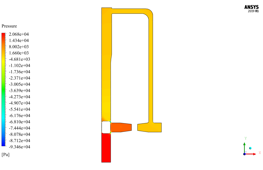
The purpose of the present simulation is to investigate the behavior of the fluid around the body of this pig inside the pipe and the pressure drop on both the upper and lower sides of the pig.
The simulation process is performed in two modes. Thus, oil flow with different inlet speeds, including 0.9 m/s and 1.9 m/s,, enters the pipeline’s interior.
Also, the VOF multi-phase model has been used to define the oil and gas materials in the pipelines and two materials have been defined as gas-oil and petro in the present model. This simulation was performed in 90 seconds with a time step of 0.03 seconds.
Geometry & Mesh
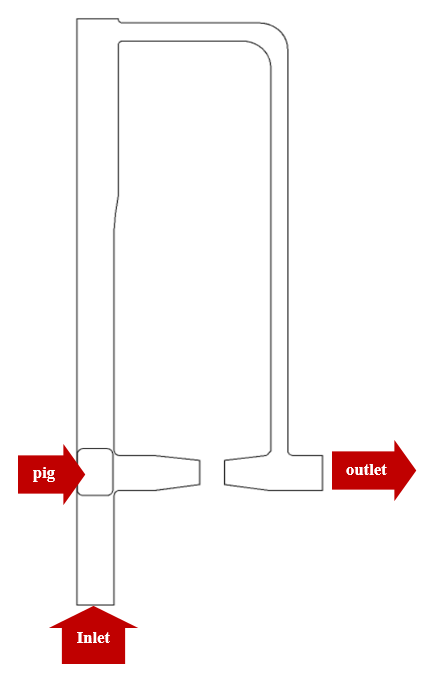
The present model is designed in two dimensions using Design Modeler software. The model includes a pipeline with a certain geometry with a simple pig inside it. The following figure shows a view of the geometry.
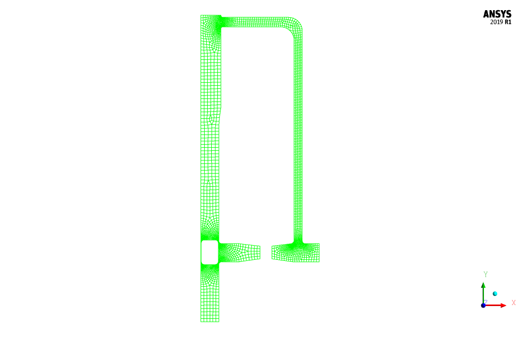
The meshing of the present model has been done using ANSYS Meshing software. The mesh type is unstructured and the element number is 5789. The following figure shows an overview of the mesh.
Pigging CFD Simulation
To simulate the present model, several assumptions are considered:
- We perform a pressure-based solver.
- The simulation is transient; the amount of pressure drop changes on the pig’s top and bottom sides have been investigated over time.
- The gravity effect on the fluid is ignored.
A summary of the defining steps of the problem and its solution is given in the following table:
| Models | ||
| Viscous | k-epsilon | |
| k-epsilon model | standard | |
| near-wall treatment | standard | |
| Multiphase Model | VOF | |
| number of Eulerian phases | 2 (gas-oil & petro) | |
| formulation | implicit | |
| interface modeling | sharp | |
| Boundary conditions | ||
| Inlet 1 | Velocity Inlet | |
| velocity magnitude | variable (0.9 & 1.9 m.s-1) | |
| volume fraction for petro | 1 | |
| volume fraction for gas-oil | 0 | |
| Outlet | Pressure Outlet | |
| gauge pressure | 0 pascal | |
| Walls (walls of pipeline & walls of pig) | Wall | |
| wall motion | stationary wall | |
| Methods | ||
| Pressure-Velocity Coupling | SIMPLE | |
| Pressure | PRESTO | |
| momentum | second-order upwind | |
| volume fraction | compressive | |
| turbulent kinetic energy | first-order upwind | |
| turbulent dissipation rate | first-order upwind | |
| Initialization | ||
| Initialization methods | Standard | |
| gauge pressure | 0 pascal | |
| x-velocity | 0 m.s-1 | |
| y-velocity | variable (0.9 & 1.9 m.s-1) | |
| petro volume fraction | 0 | |
Pigging Results
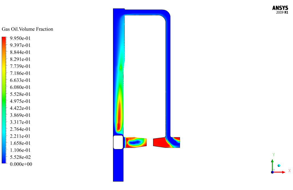
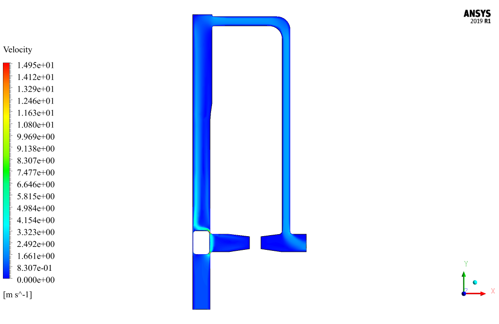
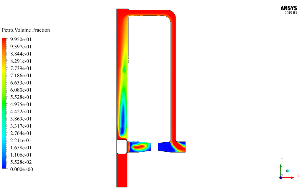
At the end of the solution process, two-dimensional contours related to the pressure, velocity, and volume fraction of each phase defined in the model are obtained. All contours of both cases are obtained at the last second of the simulation process.

Louisa Sauer –
This pigging simulation looks very detailed. Were there any challenges in modeling the interaction between the pig and the varying flow rates in the pipeline?
MR CFD Support –
In this CFD simulation, capturing the interaction between the pig and the oil flow at different velocities was handled using robust meshing and appropriate numerical settings. Special attention was given to the volume fraction settings and pressure-velocity coupling to handle the varying flow rates accurately.
Prof. Quincy Lemke II –
I followed the training for the Pigging Oil Flow in a Pipeline CFD Simulation using ANSYS Fluent and it was fantastic! The step-by-step guidance made understanding the complex interactions in the pigging process much clearer. The variation in inlet speeds adding to the complexity was well illustrated. Additionally, learning about the mesh generation and the rationale behind using an unstructured mesh type was very insightful.
MR CFD Support –
Thank you for your positive feedback! We’re delighted to hear that you found the training effective and insightful, especially with regards to understanding the complexities and mesh generation considerations in simulating pigging operations in pipelines. We strive to provide clear and detailed instruction, and we’re glad it resonated with you. Your appreciation is a testament to our commitment to quality education for our users.
David Waelchi PhD –
The level of detail in the simulation of the pigging oil flow is remarkable! The diligent work in demonstrating the pressure drop across the pig and providing such a varied inlet speed to showcase different conditions is truly commendable.
MR CFD Support –
Thank you for your kind words! We’re thrilled to hear that the comprehensive approach to the oil flow pigging simulation in ANSYS Fluent was insightful for you. Your recognition of the detail and varied conditions within the simulation validates the effort put into producing a quality educational experience. If you have any more feedback or need further information about our products, we’re always here to help!
Ms. Claire Adams –
What specific insights does this pigging simulation provide regarding pressure drop, and how can those insights be used in an actual pipeline system?
MR CFD Support –
The pigging simulation provides precise data on the pressure drop caused by the presence of a pig in the pipeline, showing how it varies with different inlet velocities. This information is crucial for pipeline engineers to optimize pigging operations, ensuring efficient maintenance and the safe transportation of fluids without undue wear on the pipeline or the pig itself.
Kenya Hackett Sr. –
I was particularly impressed with the level of detail in the simulation of pigging oil flow inside pipelines using the VOF model. The intricacy of your meshwork catering to the behavior of fluid around the pig and how it influences pressure drop is commendable. Well done!
MR CFD Support –
Thank you so much for sharing your positive experience! We’re delighted to know that you appreciated the detail and complexity of our CFD simulation of pigging oil flow. Our team works hard to provide accurate and informative simulations, and it’s great to hear we met your expectations. If you have further inquiries or need assistance with future projects, please don’t hesitate to reach out.
Kasandra Rogahn –
I love how the pigging CFD simulation captures important flow characteristics around the pig structure. This training kit clearly outlines the process and appears comprehensive for understanding pressure drop effects during pigging in pipelines. Job well done!
MR CFD Support –
Thank you for your kind words and positive feedback! We’re thrilled to hear that the Pigging Oil Flow in a Pipeline CFD Simulation has provided a thorough understanding of the process and its effects. We appreciate you taking the time to share your experience with our training product.