RQ-7 Shadow Drone CFD Simulation, ANSYS Fluent
$100.00 Student Discount
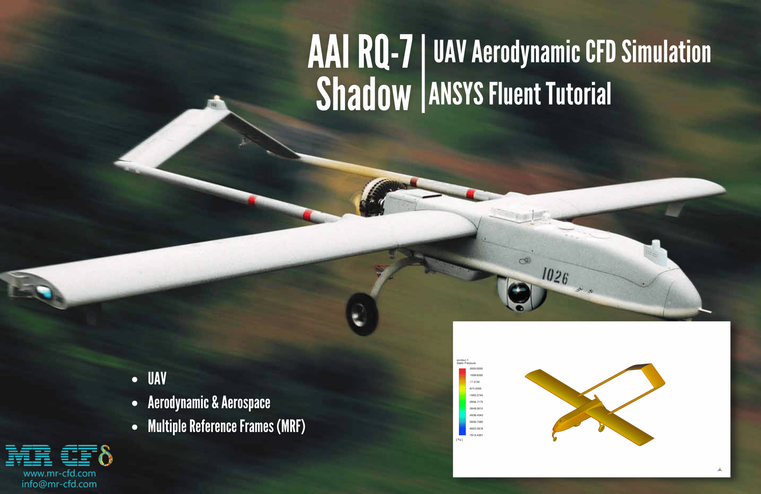
- The problem numerically simulates an AAI RQ-7 Shadow UAV using ANSYS Fluent software.
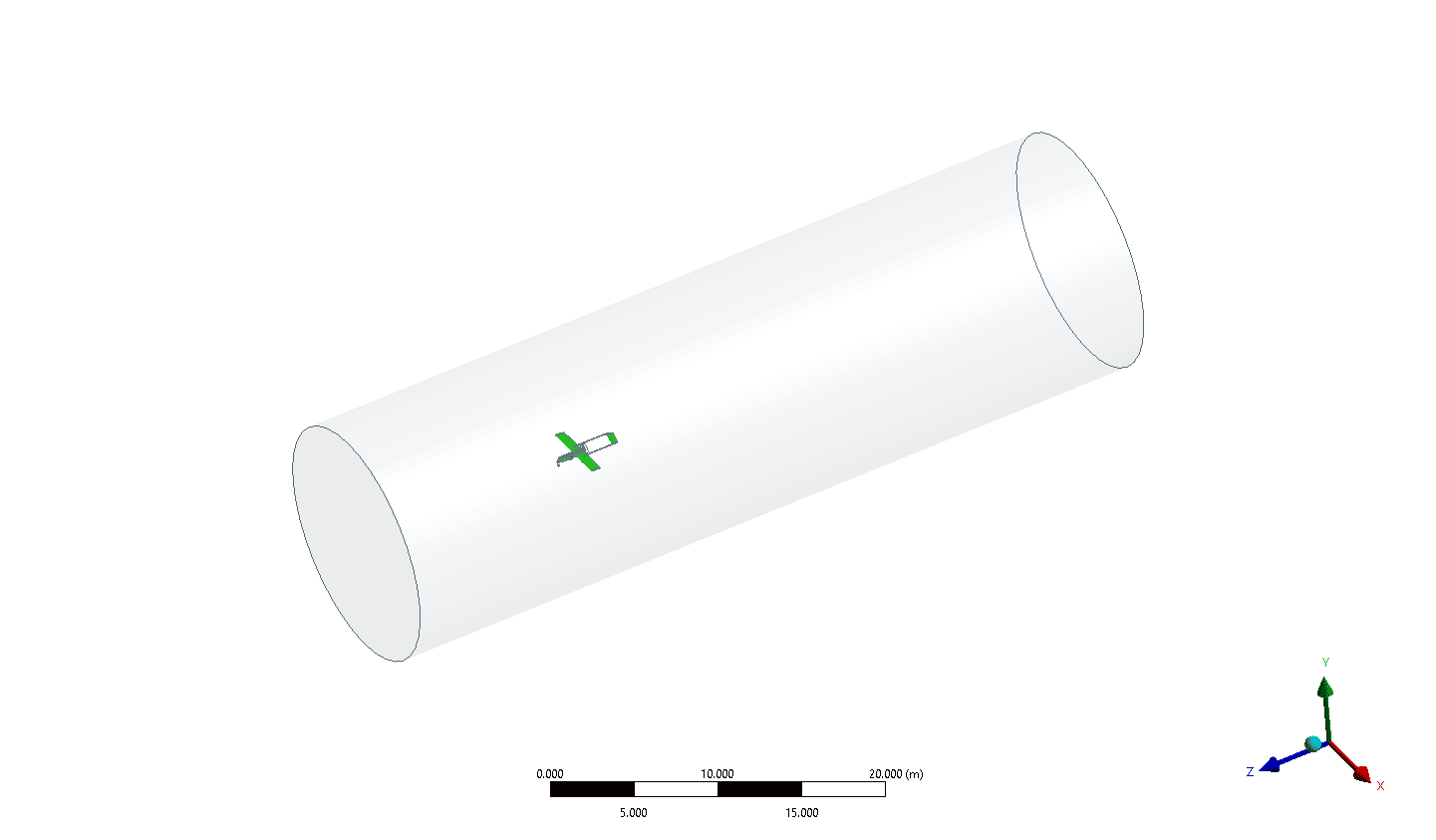
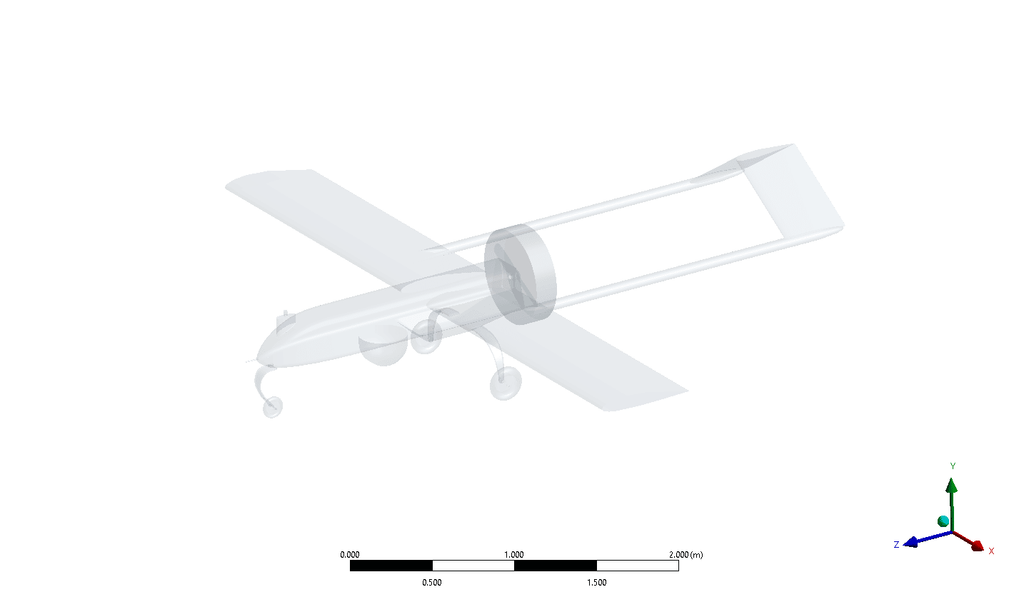
- We design the 3-D model with the Design Modeler software.
- We mesh the model with Fluent Meshing software. The element number equals 5,449,057 and their type is polyhedra.
- Multiple Reference Frames (MRF) are used to model the rotational motion of propellers.
To Order Your Project or benefit from a CFD consultation, contact our experts via email ([email protected]), online support tab, or WhatsApp at +44 7443 197273.
There are some Free Products to check our service quality.
If you want the training video in another language instead of English, ask it via [email protected] after you buy the product.
Description
AAI RQ-7 Shadow UAV CFD Simulation, ANSYS Fluent Tutorial
Introduction
The smallest of AAI’s RQ-7 Shadow family of unmanned aircraft systems is the RQ-7 Shadow 200. Targets can be found, recognized, and identified using Shadow 200 up to 125 kilometers away from a tactical center. The device can identify tactical vehicles day or night from a height of 8,000 feet and at a distance of 3.5 kilometers on a slant.
A trailer-mounted pneumatic launcher helps with takeoffs and has the ability to accelerate a 170-kilogram aircraft to 130 km/h in 12 m.
The Tactical Automatic Landing System, which consists of an aircraft-mounted transponder and a ground-based micro-millimeter wavelength radar, directs landings.
An AAI RQ-7 Shadow UAV is modeled in this simulation using ANSYS Fluent software. The device moves at a speed of 36.1 m/s while the propeller rotates at an angular velocity of 3800 rev/min.
The geometry of the present model is two-dimensional and has been designed using Design Modeler software. We do the meshing of the present model with Fluent Meshing software. The mesh type is Polyhedra, and the element number is 5,449,057.
Methodology: RQ-7 Shadow UAV CFD Simulation
The Multiple Reference Frames (MRF) method is used to model the rotational motion of the propellers.
Conclusion
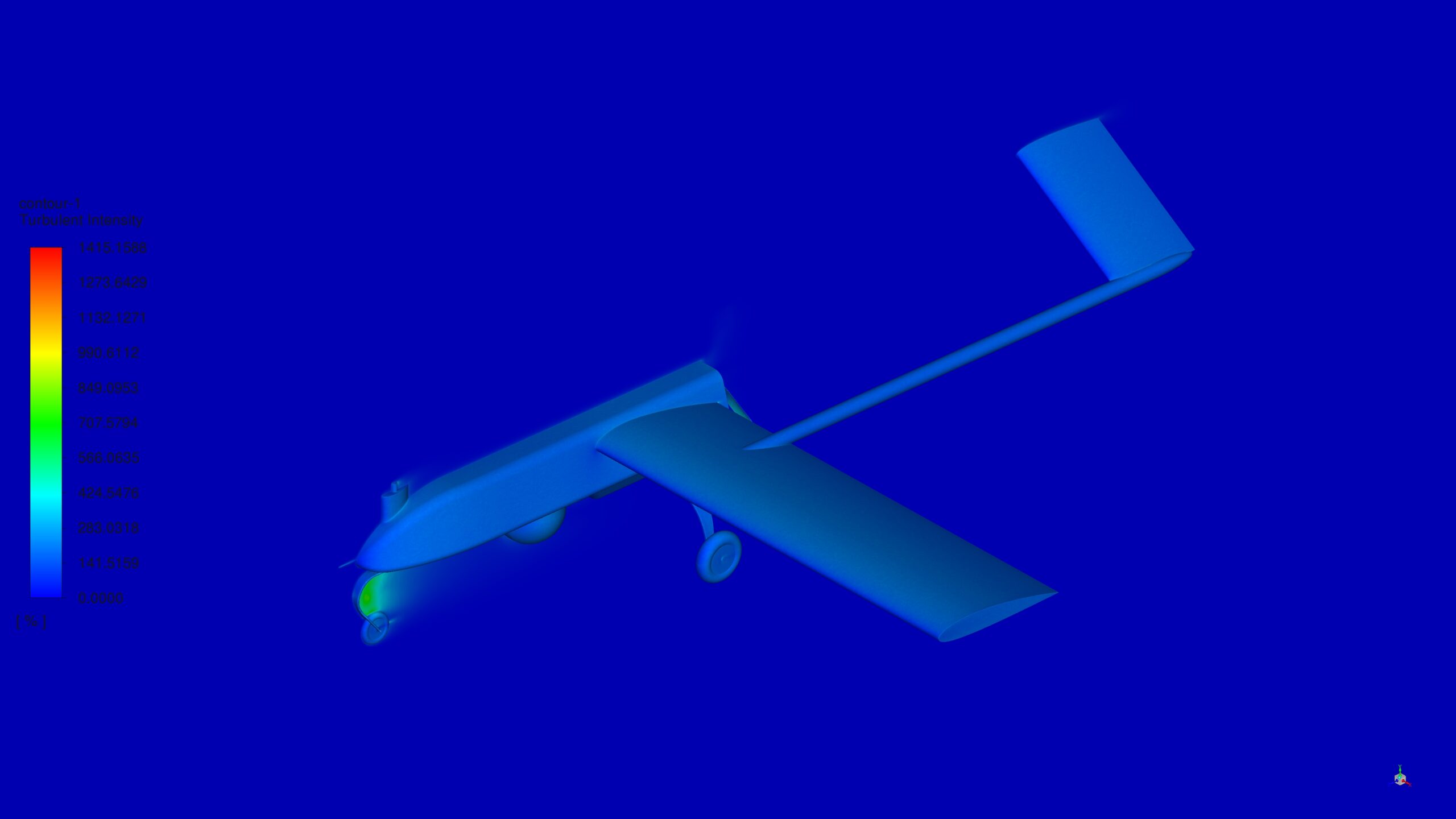
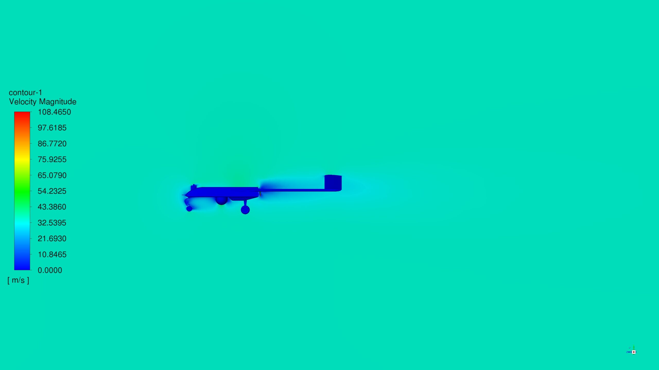
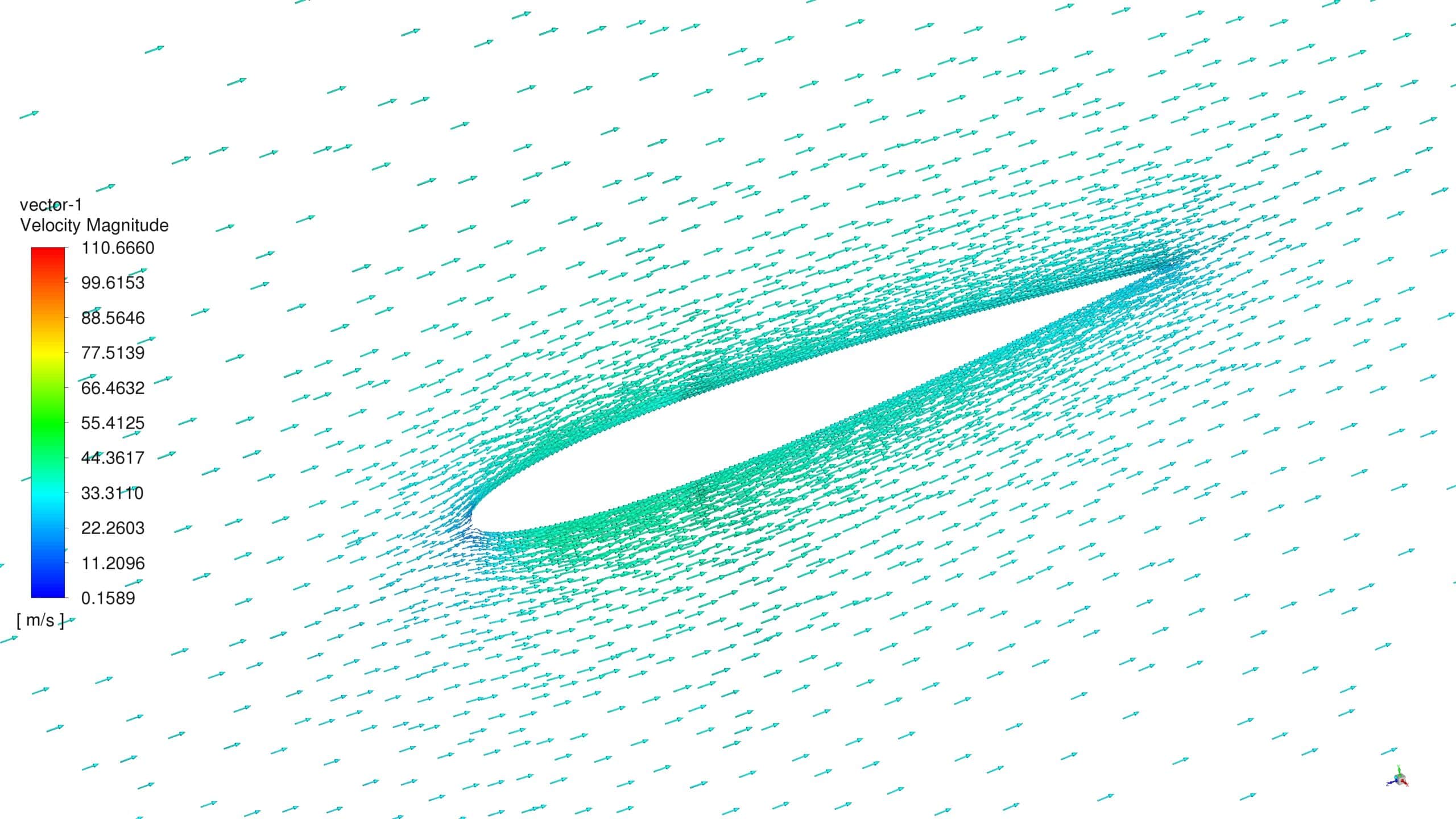
After the simulation process was finished, contours and vectors for parameters such as velocity and pressure were obtained. As shown in the velocity contours, the vortexes behind the propeller are visible. The Reverse V-tale is opposed so that these vortexes don’t hit it, which results in good dynamic stability.
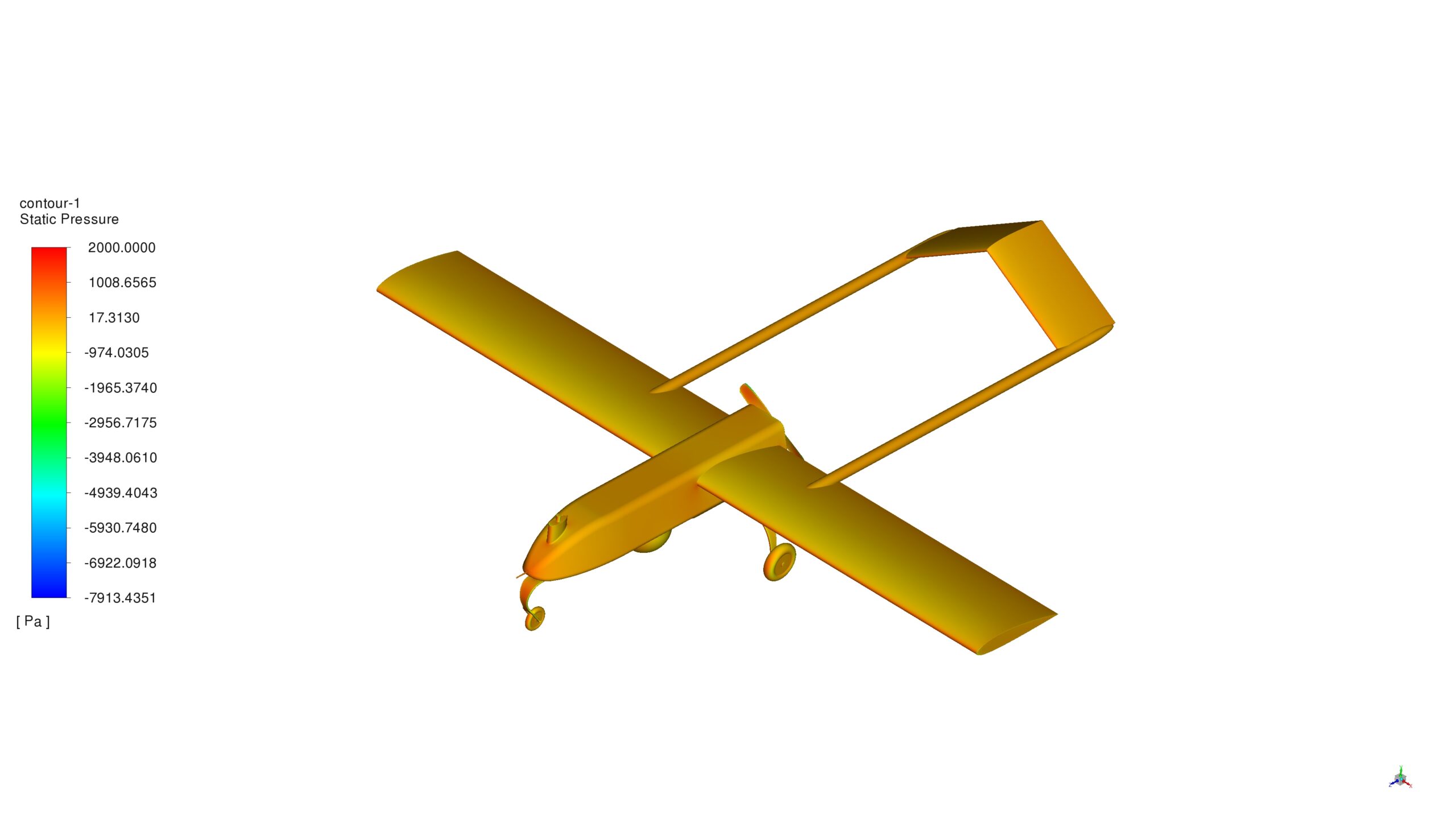
In the static pressure parameter case, as it was predictable, the UAV’s front surfaces endure the highest pressure. The maximum static pressure is applied to the propellers’ edges, which tells us about the necessity of the manufacturing focus on this component.
The force exerted in the vertical direction to the UAV is 202.80495N.

Monte O’Kon –
I am very impressed with the level of detail in the CFD simulation of the RQ-7 Shadow Drone. The use of the Multiple Reference Frames (MRF) method for the propellers appears to be quite effective. Furthermore, the insight on dynamic stability provided by the Reverse V-tail’s configuration is valuable. It’s fascinating to understand that the propeller edges experience the highest pressure, emphasizing the manufacturing considerations for these components. Thanks for the informative and thorough analysis!
MR CFD Support –
Thank you very much for your positive feedback. We’re delighted that you found the CFD simulation details of the RQ-7 Shadow Drone to be insightful and informative. It’s great to hear that you appreciate the methodology used, as well as the implications for dynamic stability and manufacturing considerations. If there’s anything more you need to know about the simulation process or if you’re interested in trying out other simulations, don’t hesitate to reach out!
Weston Zboncak –
I truly enjoyed the in-depth presentation on the RQ-7 Shadow Drone simulation using ANSYS Fluent. The detailed explanation of the methodology, especially the usage of the MRF technique for the propeller’s motion, was enlightening. Observing the resultant vortexes and understanding their implications on the UAV’s design, highlighted by the reverse V-tail for dynamic stability, was particularly exciting. This tutorial is a testament to the precision and exhaustive nature of CFD simulations in improving UAV designs.
MR CFD Support –
Thank you so much for your kind words! We’re thrilled to know that our ANSYS Fluent tutorial on the RQ-7 Shadow Drone simulation met your expectations and was helpful in understanding the sophisticated dynamics of UAV design. We always strive to provide detailed and accurate simulations to assist learners like you. If there’s anything else we can help with in your learning journey, please let us know.
Lauriane Bogisich I –
I’d never imagined a drone flight could be so vividly captured via simulation! The Forces on the propellers must have been demanding. Could you detail how the UAV maintains stability against these forces during flight?
MR CFD Support –
In the RQ-7 Shadow Drone CFD Simulation, stability is aided primarily by the unique Reverse V-tail design, which helps mitigate the effect of vortices created by the propeller. Proper aerodynamic design and advanced control systems also play significant roles in maintaining stability against the aerodynamic forces experienced during flight.
Dr. Nikki Hessel –
I recently completed my simulation study using the MR CFD product for the RQ-7 Shadow Drone Workflow and obtained excellent results and comprehensive understanding of drone aerodynamics.
MR CFD Support –
Thank you for sharing your positive experience with our RQ-7 Shadow Drone Workflow simulation study. We are delighted to hear that our product met your expectations and provided you with a thorough understanding of drone aerodynamics. If you have any further inquiry or require additional assistance from MR CFD, feel free to reach out. Your feedback is highly appreciated!
Darron Koelpin –
Thank you for the exceptionally detailed tutorial on the RQ-7 Shadow Drone CFD Simulation. The step-by-step process helped me understand the aerodynamic aspects and the effects on the propeller and tail section. I’m particularly impressed by the use of MRF methodology and how it elegantly captures the rotational motion of the propellers.
MR CFD Support –
You’re very welcome! It’s great to hear that the tutorial was helpful in understanding the complex aerodynamics of the RQ-7 Shadow Drone. We strive to provide detailed and clear instructions for a more comprehensive learning experience. If you have further questions or embark on new CFD projects, remember that our support team is here to help. Thank you for taking the time to leave a positive review.
Alek Hill –
The explanation of the RQ-7 Shadow Drone simulation is super informative! The detailing in the methodology provides such clear insights into the process. Great job!
MR CFD Support –
Thank you for your kind words! We’re really glad to hear that the information provided in our tutorial for the RQ-7 Shadow Drone CFD simulation was helpful and informative. If you have any further questions or need more clarification on any aspects, feel free to ask!
Maritza Hammes –
I recently completed my simulation project after getting the RQ-7 Shadow Drone CFD Simulation. The level of detail in the analysis was incredible. It helped me understand aerodynamic performance and I could clearly see the impact of propeller design on UAV stability. The clear presentation of high-pressure regions really highlighted manufacturing considerations.
MR CFD Support –
Thank you so much for your positive feedback! We are thrilled to hear that our RQ-7 Shadow Drone CFD Simulation product provided you with the detailed analysis required to enhance your understanding of aerodynamics in UAVs. We’re glad that you could appreciate the impacts of design on performance and stability. Your insights on manufacturing focuses are invaluable. If you need any more information or assistance with future projects, please don’t hesitate to reach out to us.
Guillermo Funk –
The tutorial was incredibly insightful! Seeing the contours and vectors really helped me grasp how the UAV’s design influences its aerodynamics. The clarity on how topological features like the Reverse V-tail contribute to dynamic stability was particularly enlightening. Excellent work on demonstrating the practical aspects of CFD in aircraft design.
MR CFD Support –
Thank you for your kind words! We’re thrilled to hear that the tutorial was helpful and provided clear insights into the aerodynamic design of the UAV. It’s gratifying to see our work contribute to a deeper understanding of the practical applications of CFD. Your feedback is greatly appreciated!
Elta Oberbrunner –
I’m completely impressed by the level of detail in the RQ-7 Shadow Drone CFD Simulation. The results helped me understand the aerodynamic properties and confirmed the necessity of reinforced propellers due to high static pressures encountered during operation. It’s clear that the MRF method effectively demonstrated the dynamic stability of the Shadow UAV. The use of polyhedral elements must have contributed to the detailed resolution of flow structures such as vortices. Fantastic simulation work!
MR CFD Support –
Thank you for your compliments on the RQ-7 Shadow Drone CFD Simulation. We’re delighted to know that the results provided you with a clear understanding of the aerodynamics involved and the structural considerations for UAV propellers. It’s gratifying to hear that the information on dynamic stability and methodologies used was helpful to you. We strive for accuracy and detail in our simulations, and feedback like yours encourages us to continue providing high-quality CFD analyses. If you need any further information or simulations, please don’t hesitate to reach out to us!
Lindsay Green –
The results you got about the vortexes and pressure sound very detailed. Can the obtained data also be used to improve the aerodynamic design of the drone’s components?
MR CFD Support –
Thank you for your kind words! Indeed, the detailed simulations, such as the velocity contours and the pressure mapping on the UAV’s structures, are critical for understanding the aerodynamic behaviors. Such data can certainly be used to identify areas that could benefit from design optimizations, ultimately leading to enhancements in performance, efficiency, and durability of the drone’s components.
Mr. Hudson Vandervort I –
Absolutely outstanding results on the RQ-7 Shadow UAV CFD Simulation! The precision and level of detail in this simulation are impressive. It’s fascinating to see the vortex patterns and how the reverse V-tail configuration enhances the drone’s dynamic stability. And the focus on manufacturing processes for the propellers based on the stress distribution is very insightful. This information is vital for design optimization. Kudos to the team for such meticulous work and clearly demonstrating the impact of pressure distribution across the UAV’s structures!
MR CFD Support –
Thank you for your positive feedback! We are thrilled to hear that you recognize the precision and detail of the RQ-7 Shadow UAV CFD simulation. It’s our aim to provide a high-quality simulation that is not only accurate but also insightful for design decision-making. Your appreciation for the vortex patterns, tail configuration analysis, and our attention to manufacturing needs based on stress distribution demonstrates that we’ve achieved our goal. Your words are truly encouraging, and it makes all of the hard work worth it. If you ever have any more questions or need further assistance, don’t hesitate to reach out. Thank you once again for your review!
Kaelyn Bechtelar –
The RQ-7 Shadow Drone analyses look comprehensive. I was particularly fascinated by how the MRF method was utilized to model the propeller motion effectively.
MR CFD Support –
Thank you for your kind words! We’re glad to hear that the application of the MRF method for modeling propeller motion in the RQ-7 Shadow Drone simulation met your expectations and provided useful insights. If you need further information or assistance with CFD simulations, feel free to reach out.
Okey McCullough –
I had a great experience learning about the RQ-7 Shadow UAV through the ANSYS Fluent tutorial. The detailed methodology and clear explanations on how to set up and conduct the CFD simulation were particularly helpful. It was fascinating to see the velocity contours and understand the impact of design on the aircraft’s stability. The information on static pressure distribution and its implications on component manufacturing caught my attention – it emphasized how simulations can inform and optimize real-world engineering practices.
MR CFD Support –
We’re delighted to hear that you had a positive experience with our RQ-7 Shadow UAV CFD Simulation tutorial. It’s wonderful to know that the information provided was helpful and insightful for you. We appreciate your feedback and are pleased the tutorial served to enrich your understanding of aerodynamics in UAV design and the significance of simulations in engineering. Thank you for sharing your impressions, and we look forward to offering you more valuable learning experiences in the future!
Mr. Deven Tremblay IV –
The tutorial was detailed and easy to follow. The visualization of the vortexes and how the Reverse V-tail design contributes to the drone’s stability was especially intriguing. Fantastic job on providing insight into complex aerodynamic concepts in a digestible manner!
MR CFD Support –
Thank you for your positive feedback! We’re thrilled to hear that the tutorial was helpful and provided a clear understanding of the RQ-7 Shadow Drone’s aerodynamics. If there are any more concepts or simulations you’re interested in, we’d be delighted to assist you. Your satisfaction is our top priority!
Alexandro Rowe –
I’m inspired by the meticulous CFD work on the RQ-7 Shadow Drone. The use of Polyhedra meshing and the detailed attention to the propeller behavior combined with dynamic stability considerations are commendable. It’s key simulations like this that push the bounds of drone technology.
MR CFD Support –
Thank you for your kind words! We’re thrilled to hear that you appreciate the detail and effort put into the RQ-7 Shadow Drone CFD simulation. It is our aim to deliver simulations that are not only technically sound but also advance the capabilities and understanding of drone technology. We look forward to providing more high-quality simulations in the future!
Dr. Rex Witting –
I’m truly impressed with the comprehensive details of the Shadow Drone’s CFD simulation. The visualization of vortex shedding around the propeller seems fascinating and indicative of the meticulous work done on aerodynamic analysis. Great job on presenting the influence of the reverse V-tail on dynamic stability.
MR CFD Support –
Thank you for your positive feedback! We’re delighted to hear that the intricate details and results of the RQ-7 Shadow Drone’s CFD simulation met your expectations. It’s encouraging to know that our efforts to provide detailed and accurate aerodynamic analysis are appreciated. If you have any further inquiries or need more information, feel free to reach out to us.
Remington Schmeler –
The RQ-7 Shadow tutorial was fantastic! Seeing the vortexes and pressure changes was intriguing. The contour lines were visual and detailed, helping me understand aerodynamic behavior around UAVs easily.
MR CFD Support –
Thank you for your review! We’re delighted to hear that our tutorial on the RQ-7 Shadow Drone CFD Simulation provided you with clear and insightful visual data. It is wonderful to know that it has helped deepen your understanding of aerodynamics in UAVs. We appreciate your feedback and hope our other tutorials will be just as useful to you.
Meta Hagenes –
I was entirely pleased with the thorough breakdown of the propulsion analysis for the RQ-7 Shadow drone. This is exactly the kind of detailed, practical application knowledge I was looking for!
MR CFD Support –
Thank you for your kind review! We’re delighted to hear that you found our propulsion analysis for the RQ-7 Shadow drone insightful and useful. Your satisfaction is our top priority, and we look forward to providing you with more high-quality learning materials.